Welcome to Arduino workshop Microcontrollers The microcontroller is


. Inputs")


: These can be inputs or outputs,")

: Configures the specified pin to behave either")
 • Goal:")


{ // statement(s) } Example: var = 0; while")
 { //statement(s); } • if else,")
 { Example: switch (var) { case")

![Arrays Create an Array Syntax: int my. Ints[6]; int my. Pins[] = {2, 4,](https://slidetodoc.com/presentation_image_h2/a7fbdc7f7c3a6d5df6c086cae62b9d54/image-43.jpg "Arrays Create an Array Syntax: int my. Ints[6]; int my. Pins[] = {2, 4,")


 pins")


")


: Sets the data rate in bits")
: Prints data to the serial port")


: Configures the specified pin to")
")


 pins. • 100 µs (0. 0001 s)")

: Reads the value from the specified")


")


 function • map(): Re-maps a number from one range to another. Value can")
 function • • • Constrains a number to be within a range. Syntax:")


 /1024. 0")


 • The term bipolar refers to the use of both")


")


 Continuous 2) Standard")

; myservo. write(pos);")

 work on")


; ultrasonic. Ranging(CM);")
- Slides: 121
Welcome to Arduino workshop
Microcontrollers • The microcontroller is a computer-on-chip. It is an integrated circuit that contains microprocessor, memory, I/O ports and sometimes A/D converters. It can be programmed using several languages (such as Assembly or C/C++). It can be used in manufacturing lines, but requires additional hardware. Microcontrollers are mainly used in engineering products such as washing machines and air-conditioners.
Microcontrollers Companies
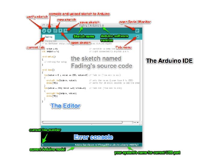
What is Arduino? An open-source hardware and software platform for building electronics projects • • A physical programmable circuit board (often referred to as a microcontroller) • A piece of software, or IDE (Integrated Development Environment) that runs on your computer, used to write and upload computer code to the physical board (supports Mac/Windows/Linux)
Arduino • Arduino is an open-source electronics prototyping platform based on flexible, easy-to-use hardware and software. • The hardware consists of a simple open source hardware board designed around an 8 -bit Atmel AVR microcontroller, though a new model has been designed around a 32 -bit Atmel ARM
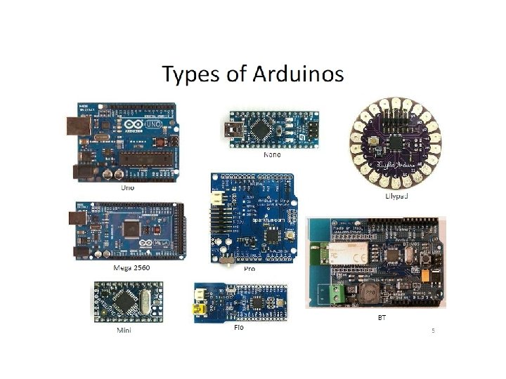
Different flavours!!! There are many versions of Arduino board. versions differ by size, microcontroller, etc
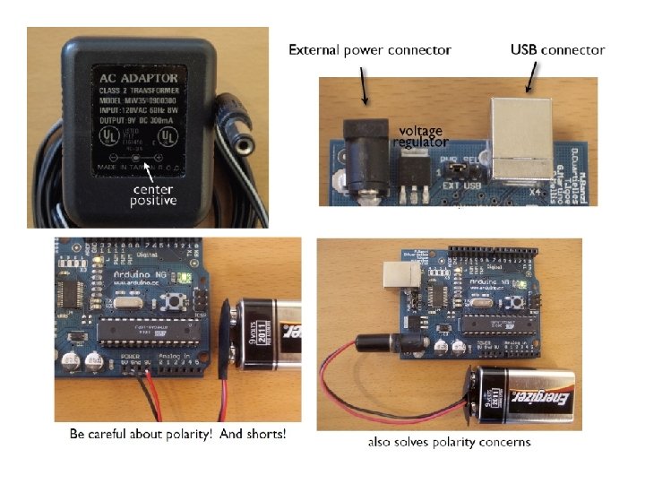
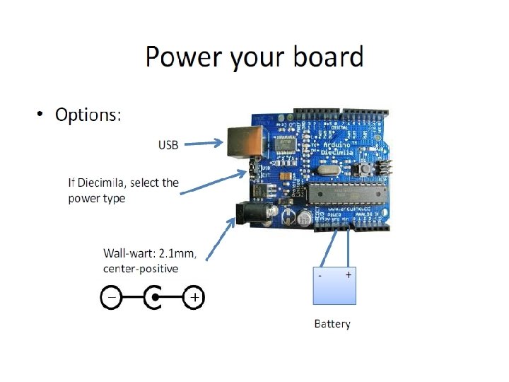
- You need an adapter with a 2. 1 mm barrel tip and a positive center. - Please note that older versions of the Arduino board (Arduino-NG and Diecimila) don’t switch automatically between an external power supply and a USB supply. - Supplying 9 volts (the recommended range is 7 V to 12 V).
ARDUINO http: //ardumap. everpi. net
Concepts: INPUT vs. OUTPUT Inputs is a signal / information going into the board. Output is any signal exiting the board. Almost all systems that use physical computing will have some form of output What are some examples of Outputs?
Concepts: INPUT vs. OUTPUT Referenced from the perspective of the microcontroller (electrical board). Inputs is a signal / information Output is any signal exiting the Examples: Buttons Switches, Light Sensors, Flex Sensors, Humidity Sensors, Temperature Sensors… Examples: LEDs, DC motor, servo motor, a piezo buzzer, relay, an RGB LED going into the board.
Concepts: Analog vs. Digital • Microcontrollers are digital devices – ON or OFF. Also called – discrete. • analog signals are anything that can be a full range of values. What are some examples? More on this later… 5 V 5 V 0 V 0 V
Digital or Analog? Digital and analog. All physical quantities are analog. Analog means that the quantity can take any value between its minimum value and maximum value. Digital means that the quantity can take specific levels of values with specific offset between each other. Ex: 1 - Digital: English alpha consists of 26 letter, there is no letter between A and B. - Square waves are Digital. Ex. : 2 - Analog: Temperature, can take any value[-1, 12. 8, 25. 002, … etc. ]. - Sine waves are analog.
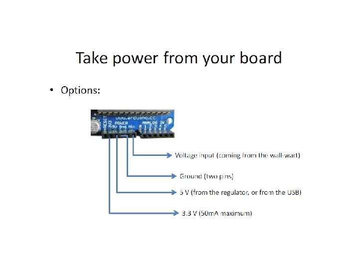
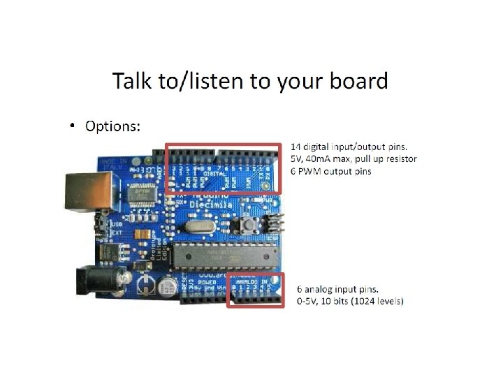
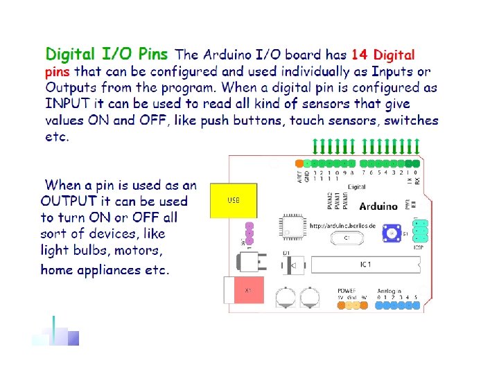
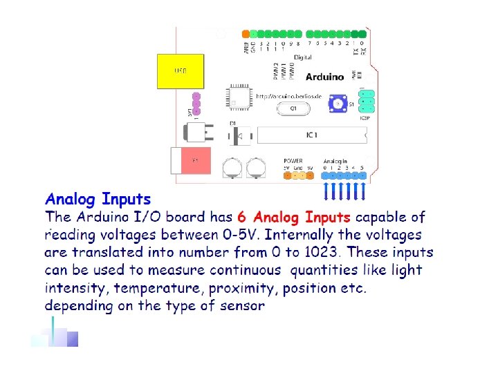
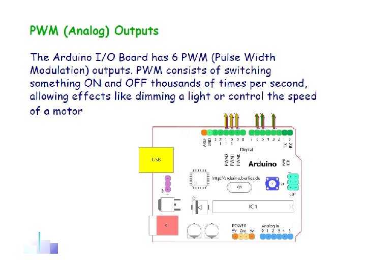
- 14 Digital IO pins (pins 0– 13): These can be inputs or outputs, which is specified by the sketch you create in the IDE. - 6 Analogue In pins (pins 0– 5): These dedicated analogue input pins take analogue values (i. e. , voltage readings from a sensor) and convert them into a number between 0 and 1023. - 6 Analogue Out pins (pins 3, 5, 6, 9, 10, and 11): These are actually six of the digital pins that can be reprogrammed for analogue output using the sketch you create in the IDE.
BASIC I/O - DIGITAL WRITES
DIGITAL WRITE – KEY CONCEPTS pin. Mode(): Configures the specified pin to behave either as an input or an output Syntax: pin. Mode(pin, mode) • Example: pin. Mode(13, OUTPUT) set pin 13 to output mode Example: pin. Mode(13, INPUT) set pin 13 to input mode • • digital. Write(): Write a HIGH or a LOW value to a digital pin If set to OUTPUT with pin. Mode(), 5 V (or 3. 3 V on 3. 3 V boards) for HIGH, 0 V (ground) for LOW. Syntax: digital. Write(pin, value) Example 1: digital. Write(13, HIGH) is 5 volts to pin 13 Example 2: digital. Write(13, LOW) is 0 volts to pin 13
Action Round #1– Blink LED • Project Name: Blink LED (Instructor Lead) • Goal: Turns LED on for one second, then off for one second, repeatedly Software • pin. Mode() • digital. Write() • delay() • Hardware • • • 5 mm LED (1) 220 Ohm Resister (1) Arduino Uno (1) Breadboard Jumper Wires
Breadboard Layout Connected dots represent connectivity
LED BASIC How to tell between anode and cathode? Features: A basic 5 mm LED with a red lens. 1. 8 -2. 2 VDC forward drop Max current: 20 m. A Suggested using current: 16 -18 m. A Luminous Intensity: 150 -200 mcd Safety Tips: Must use a pull-up resister to connect to 5 V source! Math: (5 V-1. 8 V)/16 m. A = 200 ohm Pick: 220 ohm resister
Action Round #1– Blink LED Hardware • Software • Connect Arduino Vcc and GND to breadboard power rails • • Put in a LED on breadboard • D 13> 220 Ohm resister -> LED -> GND • • • • • • /* Blink Turns on an LED on for one second, then off for one second, repe atedly. This example code is in the public domain. */ // Pin 13 has an LED connected on most Arduino boards. // give it a name: int led = 13; // the setup routine runs once when you press reset: void setup() { // initialize the digital pin as an output. pin. Mode(led, OUTPUT); } // the loop routine runs over and over again forever: void loop() { digital. Write(led, HIGH); // turn the LED on (HIGH is the voltage level) delay(1000); // wait for a second digital. Write(led, LOW); // turn the LED off by making the voltage LOW delay(1000); // wait for a second }
Digital Design • Using your own circuit design and Arduino sketch, design a solution that solves the following challenges. • Challenge 1 a: Add a Second LED to the circuit and make them Blink together. • Challenge 1 b: Then make them Blink alternating on and off.
Digital Design • Challenge 1 a: Add a Second Software LED to the circuit and make /* Blink two LEDs together them Blink together Modified by Matt Royer May 5, 2014 */ // Pin 13 has an LED connected on most Arduino boards. // give it a name: int led 1 = 13; int led 2 = 12; // Additional LED Pin // the setup routine runs once when you press reset: void setup() { // initialize the digital pin as an output. pin. Mode(led 1, OUTPUT); pin. Mode(led 2, OUTPUT); // Additional LED Pinmode } // the loop routine runs over and over again forever: void loop() { digital. Write(led 1, HIGH); // turn the LED on (HIGH is the voltage level) digital. Write(led 2, HIGH); // turn the LED on (HIGH is the voltage level) delay(1000); // wait for a second digital. Write(led 1, LOW); // turn the LED off by making the voltage LOW digital. Write(led 2, LOW); // turn the LED off by making the voltage LOW delay(1000); // wait for a second }
Digital Design • Challenge 1 b: Make them Blink Alternating on and Software off. /* Blink two LEDs together Modified by Matt Royer May 5, 2014 */ // Pin 13 has an LED connected on most Arduino boards. // give it a name: int led 1 = 13; int led 2 = 12; // Additional LED Pin // the setup routine runs once when you press reset: void setup() { // initialize the digital pin as an output. pin. Mode(led 1, OUTPUT); pin. Mode(led 2, OUTPUT); // Additional LED Pinmode } // the loop routine runs over and over again forever: void loop() { digital. Write(led 1, HIGH); // turn the LED on (HIGH is the voltage level) digital. Write(led 2, LOW); // turn the LED on (HIGH is the voltage level) delay(1000); // wait for a second digital. Write(led 1, LOW); // turn the LED off by making the voltage LOW digital. Write(led 2, HIGH); // turn the LED off by making the voltage LOW delay(1000); // wait for a second }
Control structures • while Syntax: while(expression){ // statement(s) } Example: var = 0; while (var < 200) { // do something repetitive 200 times var++; }
Control structures • If Syntax: if (boolean condition) { //statement(s); } • if else, if else if, else Syntax: if (condition 1) { // do Thing A } else if (condition 2) { // do Thing B } … }else { // do Thing C }
Control structures • switch case Syntax: switch (var) { Example: switch (var) { case label: case 1: // statements //do something when var break; equals 1 break; case label: case 2: // statements break; default: //do something when var equals 2 break; // statements Default: } // if nothing else matches, do the default // default is optional }
Try adding other LEDs •
Arrays Create an Array Syntax: int my. Ints[6]; int my. Pins[] = {2, 4, 8, 3, 6, 1}; int my. Sens. Vals[6] = {2, 4, -8, 3, 2, 0}; char message[6] = "hello!"; Access an Array index starts from 0. int my. Array[10]={9, 3, 2, 4, 3, 2, 7, 8, 9, 11}; // my. Array[9] contains 11 // my. Array[10] is invalid and contains random information (other memory address) To assign a value to an array my. Sens. Vals[0] = 10; To retrieve a value from an array: x = my. Sens. Vals[4];
Arrays and for-loop • Arrays are often manipulated inside for loops, where the loop counter is used as the index for each array element. For example, to print the elements of an array over the serial port, you could do something like this: • Example: • • • int i; int my. Pins[3] = {0, 1, 2}; for (i = 0; i < 3; i = i + 1) { digital. Write(my. Pins[i], HIGH); delay(2000); //delay for 2 seconds }
Action Round #2: 3 LEDs blink in series and • repeat. Goal: take turn • You’ll be using: for loop, array, delay() Software • pin. Mode() • digital. Write() • array [ ] • for loop • delay() • Hardware • • • 5 mm LED (3) 220 Ohm Resister (3) Arduino Uno (1) Breadboard Jumper Wires
• Action Round #2: 3 LEDs blink in series and repeat. Software /* Blink Cycle through Array list of LEDs. For each LED in Array turns it on for 1 second. Modified by Matt Royer May 5, 2014 */ const int number. Of. LED = 3; // Number of LED in Array const int l. EDTo. Blink[number. Of. LED] = { // Array to store LED Pins 13, 12, 11 }; // the setup routine runs once when you press reset: void setup() { // initialize the digital pin as an output // For each LED in Array, initialize for (int initalize. LED = 0; initalize. LED < number. Of. LED; initalize. LED++){ pin. Mode(l. EDTo. Blink[initalize. LED], OUTPUT); } } // the loop routine runs over and over again forever: void loop() { for (int light. LED = 0; light. LED < number. Of. LED; light. LED++){ // For each LED in Array, Blink digital. Write(l. EDTo. Blink[light. LED], HIGH); // turn the LED on (HIGH is the voltage level) delay(1000); digital. Write(l. EDTo. Blink[light. LED], LOW); // turn the LED on (HIGH is the voltage level) } }
Programming Concepts: Variables Variable Scope • Global • --- • Function-level
Programming Concepts: Variable Types • Variable Types: 8 bits byte char 16 bits int unsigned int 32 bits long unsigned long float
BASIC I/O - ANALOG WRITES
ANALOG WRITE • PWM pins ONLY • 8 bit resolution • (GPIO) pins
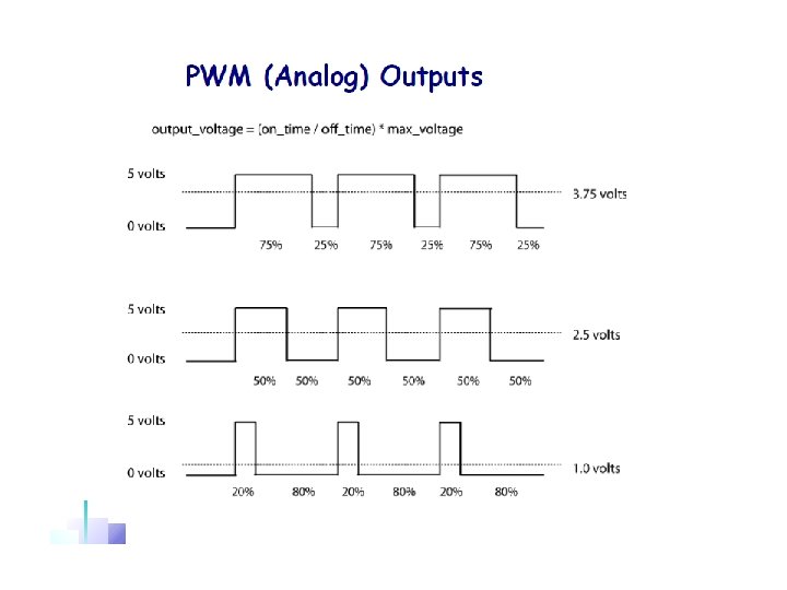
Pulse Width Modulation • In Summary: PWM is a technique for getting analog results with digital means. To be exact, a signal is switched between on and off to create a square wave, by controlling the percentage of time the signal is on (duty cycle), we simulate “a steady analog source” which can be considered as “ the digital average”. • Vanalog = Vdigital * Duty. Cycle • The table shows relation between • PWM duty cycle and simulated • analog voltage, assume Vdigital = 5 V 0 V 1. 25 V 2. 5 V 3. 75 V 5 V
Pulse Width Modulation • How to use in Arduino ? • Identify the pins: PWM is supported on Pin 3, 5, 6, 9, 10, 11 , with a “~” • Modulate pulse width by calling analog. Write() • analog. Write ranges from 0 -255, with 0 being 0% duty cycle, 255 being 100% • For example, 50% duty cycle is 255*50% = 127, analog. Write(PIN, 127) makes the analog output looks like it’s connected to a steady 2. 5 V source • Provide 8/12 bit PWM output with the analog. Write() function. The resolution of the PWM can be changed with the analog. Write. Resolution() function.
Analog Write – Key Concepts • Arduino Default PWM is 8 bit void Setup() • pin. Mode(): Configures the specified pin to behave either as an input or an output • Example: pin. Mode(11, OUTPUT) void loop() • analog. Write(): Writes an analog value (Pulse Width Modulation wave) to a pin. • Example: analog. Write (11, 64) • • Q: What’s the Duty Cycle does 64 represent, suppose PWM precision is 8 bit ? Hint: the max number can be represented by 8 bit is
Action Round#1 – Fading LED using analog Write Goal: Change the brightness of an LED using PWM to make it appear to fade in and out by itself You will be using: Analog Write and Serial Monitor Software • analog. Write() • pin. Mode() • Hardware • • 5 mm LED (1) 220 Ohm Resister (1) Breadboard Jumper Wires
BASIC I/O - SERIAL WRITES
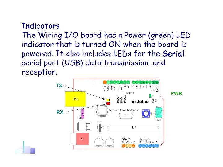
Refresher: Arduino Serial Interfaces • Used for communication between the Arduino board and a computer or other devices. • Arduino platforms have at least one serial port (also known as a UART or Universal Asynchronous Receiver/Transmitter) • Serial Communicates through digital pins 0 (RX) & 1 (TX) and via USB to Computer for Sketches
Serial Write – Key Concepts • Serial. begin(): Sets the data rate in bits per second (baud) for serial data transmission • Syntax: Serial. begin(baud) • Example: Serial. begin(9600) sets serial baud rate to 9600 bits per second • Serial. print(): Prints data to the serial port as human-readable ASCII text without carriage return / Newline Feed character • Syntax: Serial. print(val) or Serial. print(val, format) • Parameters: • val: the value to print - any data type • format: specifies the number base or number of decimal places • Example: Serial. print(”Hello world. “) gives "Hello world. “ • Example: Serial. print(1. 23456, 2) gives “ 1. 23”
Serial Write – Key Concepts • Serial. println(): Prints data to the serial port as human-readable ASCII text followed by a carriage return and a newline character • Syntax: Serial. println(val) or Serial. print(val, format) • Parameters: • val: the value to print - any data type • format: specifies the number base or number of decimal places • Example: Serial. println(”Hello world. “) gives "Hello world. “ • Example: Serial. println(1. 23456, 2) gives “ 1. 23” • Serial. write(): Writes binary data to the serial port. This data is sent as a byte or series of bytes • Syntax: Serial. write(val) • Example: Serial. wrtie(”Hello world“) writes "Hello world“
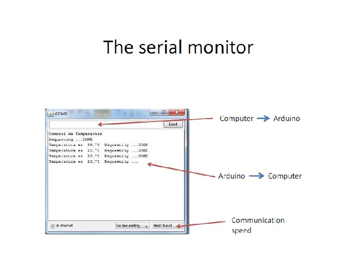
Bring up Serial Monitor • Select “Tools” -> “Serial Monitor” or click Serial Monitor Icon Note: Sketch must be loaded first; else, Serial Monitor will close on Sketch upload OR
BASIC I/O - DIGITAL READS
Digital Read – Key Concepts • Reminder pin. Mode(): Configures the specified pin to behave either as an input or an output • Syntax: pin. Mode(pin, mode) • Example: pin. Mode(2, OUTPUT) set pin 2 to output mode • Example: pin. Mode(2, INPUT) set pin 2 to input mode • digital. Read(): Reads the value from a specified digital pin, either HIGH or LOW • Syntax: pin. Mode(pin) • Example 1: digital. Read(2) reads High or Low from pin 2
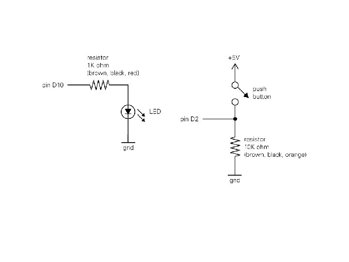
Action Round#1: Digital Read from push button • Project Name: LED Button Press(Instructor Lead) • Goal: Illuminate LED when push button is being pressed Software • Hardware • pin. Mode() • digital. Write() • digital. Read() • if / else • • • 5 mm LED (1) Momentary Switch/push button (1) 220 Ohm Resister (1) 10 k Ohm Resister (1) Arduino (1) Breadboard Jumper Wires
Action Round#1: Digital Read from push button Hardware • Connect power rails to breadboard • D 13>220 ohm->anode->cathode->GND • Vcc->10 k ohm-> pushbutton->GND • D 2 ->pushbutton and resistor junction point Software // constants won't change. They're used here to // set pin numbers: const int button. Pin = 7; // the number of the pushbutton pin const int led. Pin = 13; // the number of the LED pin // variables will change: int button. State = 0; // variable for reading the pushbutton status void setup() { // initialize the LED pin as an output: pin. Mode(led. Pin, OUTPUT); // initialize the pushbutton pin as an input: pin. Mode(button. Pin, INPUT); } void loop(){ // read the state of the pushbutton value: button. State = digital. Read(button. Pin); } // check if the pushbutton is pressed. // if it is, the button. State is HIGH: if (button. State == HIGH) { // turn LED on: digital. Write(led. Pin, HIGH); } else { // turn LED off: digital. Write(led. Pin, LOW); } * Other names and brands may be claimed as the property of others
Action Round #2: Blink LED continuously while button is pressed • Goal: when button is pressed, blink LED continuously • Software You’ll be using: if , delay() Hardware • pin. Mode() • 5 mm LED (1) • digital. Write() • Momentary Switch/push button (1) • if • 220 Ohm Resister (1) • delay() • 10 k Ohm Resister (1) • Intel Galileo Board (1) Breadboard Jumper Wires
• Action Round #3: Blink LED continuously while button is pressed Hardware • Connect power rails to breadboard • D 13>220 ohm->anode->cathode->GND • Vcc->10 k ohm-> pushbutton->GND • D 2 ->pushbutton and resistor junction point Software // constants won't change. They're used here to // set pin numbers: const int button. Pin = 2; // the number of the pushbutton pin const int led. Pin = 13; // the number of the LED pin // variables will change: int button. State = 0; // variable for reading the pushbutton status void setup() { // initialize the LED pin as an output: pin. Mode(led. Pin, OUTPUT); // initialize the pushbutton pin as an input: pin. Mode(button. Pin, INPUT); } void loop(){ // read the state of the pushbutton value: button. State = digital. Read(button. Pin); // check if the pushbutton is pressed. // if it is, the button. State is HIGH: } if (button. State == HIGH) { digital. Write(led. Pin, HIGH); delay(500); digital. Write(led. Pin, LOW); delay(500); } digital. Write(led. Pin, LOW); * Other names and brands may be claimed as the property of others
Action Round #3: Press button to turn on and off LED • Goal: when button is pressed and released first time, turn on LED; and the second time, turn off LED; and continues turning on and off Hardware Software LED with each press and release of button • 5 mm LED (1) • pin. Mode() • digital. Write() • Momentary Switch/push button (1) • digital. Read() • 220 Ohm Resister (1) • If • 10 k Ohm Resister (1) • boolean variable • Intel Galileo Board (1) • boolean operation (!) Breadboard • delay() Jumper Wires
• Action Round #3: Blink LED continuously while button is pressed Software const int button. Pin = 2; // the number of the pushbutton const int led. Pin = 13; boolean led. State = false; boolean buttondown = false; // variables will change: void setup() { // initialize the relay pin as an output: pin. Mode(led. Pin, OUTPUT); pin. Mode(button. Pin, INPUT); } void loop(){ //get the button State by using digital. Read buttondown = digital. Read(pushbutton); } if(buttondown){ //invert the led. State if button is pressed led. State = !led. State; //Write inverted state to LED digital. Write(led. Pin, led. State); } delay(200); //delay is necessary to stabilize the processing, not allowing immediate input from pushbutton * Other names and brands may be claimed as the property of others
BASIC I/O ANALOG READ
Analog signals. • Analog signal is any continuous signal Vs. time! • digital signal uses discrete (discontinuous) values.
ANALOG READ – BOARD HARDWARE
• 10 bit resolution. • (GPIO) pins. • 100 µs (0. 0001 s) to read an analog input. reading rate = 10, 000 /s
Analog sensors LM 35 LDR Potentiometer
Analog Read – Key Concepts • analog. Read(): Reads the value from the specified analog pin. • Syntax: analog. Read(pin) • Example: analog. Read(A 0) reads analog value of pin A 0
Action- Round #1 Read Value from potentiometer • Goal: Read the voltage adjusted by potentiometer and print out on Serial Monitor • You will be using: Analog Read and Serial Monitor • Hardware Software • analog. Read() • Serial. println() • Potentiometer(1) Breadboard Jumper Wires
Action- Round #1 Read Value from potentiometer • Hardware • • Connect Galileo Vcc and GND to breadboard power rails Put in a potentiometer(POT) on breadboard Connect POT middle pin to A 0 Connect POT other two pins to Vcc, GND on breadboard respectively Software void setup() { // initialize serial communication at 9600 bits per second: Serial. begin(9600); } // the loop routine runs over and over again forever: void loop() { // read the input on analog pin 0: int sensor. Value = analog. Read(A 0); // print out the value you read: Serial. println(sensor. Value); // delay in between reads for stability delay(500); }
Action- Round #1 Read Value from potentiometer Observation • What is the range of potentiometer output? • Why is it represented in numbers rather than actual voltage?
Data Types — Floating point • Syntax: A. float var = val; B. (float) var -- type casting • Example: • A. float x= 1. 25; • B. int x; • int y; • float z; • x = 1; • y = x / 2; // y now contains 0, int can't hold fractions • z = (float)x / 2. 0; // z now contains 0. 5 (you have to use 2. 0, not 2)
Action- Round #3 Read Value from POT and convert it to true floating point value void setup() { // initialize serial communication at 9600 bits per second: Serial. begin(9600); } // the loop routine runs over and over again forever: void loop() { // read the input on analog pin 0: int sensor. Value = analog. Read(A 0); // print out the value you read: Serial. println(sensor. Value); // delay in between reads for stability delay(500); } Hint: • The range of POT voltage output is 0 to 5 V • Define a floating point variable, ex. float v. POT; • v. POT = sensor. Value/sensor. Full. Range * 5. 0 • Don’t forget the type casting!
Action Round#4 Calibration – Calibrating analog input to fit digital range Goal: Given an analog input source whose range is unknown, map the range to the digital representation at initial setup time You will be using: millis(), map(), Analog Read, Serial Monitor Software • analog. Write() • pin. Mode() • Hardware • • • 5 mm LED (2) 220 Ohm Resister (2) Potentiometer Breadboard Jumper Wires
Action Round#3 Calibration – Calibrating analog input to fit digital Software range • First run the code -> File->Example-> Analog->Calibration Add Serial Print to monitor Print out the Sensor Min value and Sensor Max value to see how it changes as flex sensor is being bent. Serial. begin(9600); • Serial. print("Calibration time sensor. Min = "); Serial. println(sensor. Min); Serial. print("Calibration time sensor. Max = "); Serial. println(sensor. Max); Making the Calibration time longer and add delay function if necessary to better observe in Serial Monitor. while (millis() < 10000) { … delay(100); }
Map() function • map(): Re-maps a number from one range to another. Value can be mapped to values that are out of range. • Syntax: map(Source, from. Low, from. High, to. Low, to. High) • Example: map(val, 0, 1023, 0, 255) • Useful for dealing with different precisions/representations, 5 V is represented as 1023 previously, now as 255. • For example:
Constrain() function • • • Constrains a number to be within a range. Syntax: constrain(x, a, b) Returns: x: if x is between a and b a: if x is less than a b: if x is greater than b Example: sens. Val = constrain(sens. Val, 10, 150); // limits range of sensor values to between 10
Action Round #4 – Read and Serial Print Map Value Software const int analog. In. Pin = A 0; // Analog input pin that the potentiometer is attached to //const int analog. Out. Pin = 11; // Analog output pin that the LED is attached to int sensor. Value = 0; int output. Value = 0; // value read from the pot // value output to the PWM (analog out) void setup() { // initialize serial communications at 9600 bps: Serial. begin(9600); } void loop() { // read the analog in value: sensor. Value = analog. Read(analog. In. Pin); // map it to the range of the analog out: output. Value = map(sensor. Value, 0, 1023, 0, 255); // change the analog out value: // analog. Write(analog. Out. Pin, output. Value); // print the results to the serial monitor: Serial. print("sensor = " ); Serial. print(sensor. Value); Serial. print("t output = "); Serial. println(output. Value); } // wait 2 milliseconds before the next loop // for the analog-to-digital converter to settle // after the last reading: delay(200);
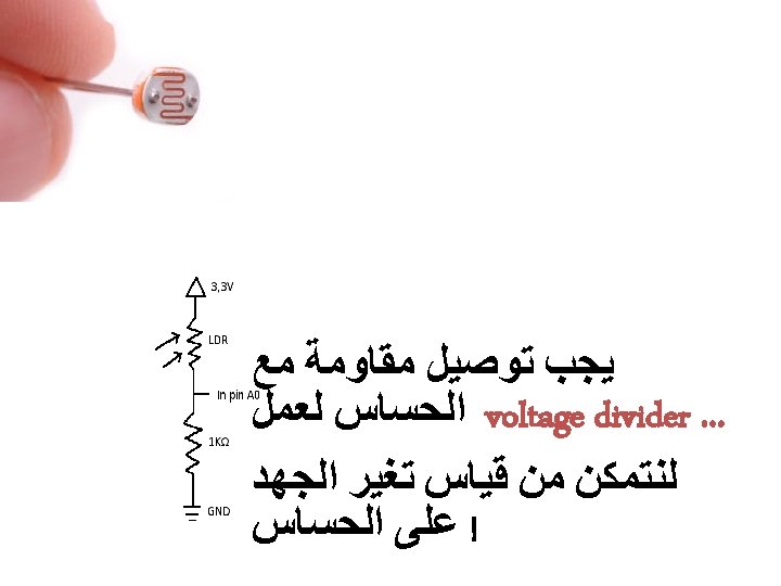
LDR Light Dependent Resistor
Schematic Diagram
LM 35 The LM 35 series are precision integrated-circuit temperature devices with an output voltage linearly-proportional to the Centigrade temperature. Features Calibrated Directly in Celsius (Centigrade) Linear + 10 -m. V/°C Scale Factor 0. 5°C Ensured Accuracy (at 25°C) Rated for Full − 55°C to 150°C Range Suitable for Remote Applications Low-Cost Due to Wafer-Level Trimming Operates from 4 V to 30 V Less than 60 -μA Current Drain Low Self-Heating, 0. 08°C in Still Air Non-Linearity Only ±¼°C Typical Low-Impedance Output, 0. 1 Ω for 1 -m. A Load
Analogue or Digital ? ! ^_^ ) /1024. 0
Enough with LED, Let’s play with motors! • DC motors • Direct Current controlled motor, using two wires to connect to Power and Ground • Servo motors • • A servomotor is a rotary actuator that allows for precise control of angular position, velocity and acceleration. 0 -180 degrees
DC Motor • The most common actuator in mobile • robotics is the direct current (DC) motor • Advantages: simple, cheap, various sizes and packages, easy to interface, clean. • DC motors convert electrical into mechanical energy.
DC Motor • DC motors consist of permanent magnets with loops of wire inside • When current is applied, the wire loops generate a magnetic field, which reacts against the outside field of the static magnets • The interaction of the fields produces the movement of the shaft/armature • A commutator switches the direction of the current flow, yielding continuous motion
Problem !!!! • Motors need at least 200 m. A to start on ! >_< • How could I do this from arduino ? ! ^_^
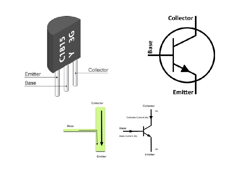
Transistors
Transistor History • Invention: 1947, at Bell Laboratories. • John Bardeen, Walter Brattain, and William Schockly developed the first model of transistor (a Three Points transistor, made with Germanium) • They received Nobel Prize in Physics in 1956 "for their researches on semiconductors and their discovery of the transistor effect" • First application: replacing vacuum tubes (big & inefficient). • Today: millions of Transistors are built on a single silicon wafer in most common electronic devices First model of Transistor
What is a transistor ? • The Transistor is a three-terminal, semiconductor device. • It’s possible to control electric current or voltage between two of the terminals (by applying an electric current or voltage to the third terminal). The transistor is an active component. With the Transistor we can make amplification devices or electric switch. Configuration of circuit determines whether the transistor will work as switch or amplifier As a miniature electronic switch, it has two operating positions: on and off. This switching capability allows binary functionality and permits to process information in a microprocessor.
Bipolar Junction Transistors (BJT’s) • The term bipolar refers to the use of both holes and electrons as charge carriers in the transistor structure • There are two types of BJTs, the NPN and PNP
Transistor symbols
Transistor operation force – voltage/current water flow – current - amplification
Connection Why we need the diode ? !
Connection on breadboard
Speed of the Motor ? !
PWM
What about Direction ? !
H-Bridge
H-Bridge
IC ( L 293 B )
Connections
Servo Motor • It is sometimes necessary to move a motor to a specific position DC motors are not built for this purpose, but servo motors are Servo motors are adapted DC motors: • gear reduction • position sensor (potentiometer) • electronic controller • Range of at least 180 degrees
Servo Motor 1) Continuous 2) Standard
Servo Motor
Servo Library #include <Servo. h> Servo myservo ; myservo. attach(9); myservo. write(pos);
Ultrasonic Sensor An ultrasonic transducer is a device that converts energy into ultrasound, or sound waves above the normal range of human hearing. Systems typically use a transducer which generates sound waves in the ultrasonic range, above 18, 000 hertz, by turning electrical energy into sound, then upon receiving the echo turn the sound waves into electrical energy which can be measured and displayed.
Ultrasonic sensors (also known as transceivers when they both send and receive) work on a principle similar to radar or sonar which evaluate attributes of a target by interpreting the echoes from radio or sound waves respectively. Ultrasonic sensors generate high frequency sound waves and evaluate the echo which is received back by the sensor. Sensors calculate the time interval between sending the signal and receiving the echo to determine the distance to an object.
Interfacing & Features • • description: ultrasonic transducer - receiver max. input voltage: 20 Vrms operating temperature: -20°C to +85°C range: 0. 04 to 4 m nominal frequency: 40 k. Hz sensitivity: -67 d. B min. sound pressure: 112 d. B min.
Ultrasonic
Ultrasonic
Applications
Ultrasonic Library #include "Ultrasonic. h“ Ultrasonic ultrasonic(TRIGGER_PIN , ECHO_PIN); ultrasonic. Ranging(CM);