ADC DAC Interfacing with 8051 Microcontroller Presented by
")
ADC - DAC Interfacing with 8051 Microcontroller Presented by Dr. Jayant Mahakhode (jayantmahakhode@gmail. com) Head, Department of Electronics D. B. Science College, Gondia. 441614

ADC Interfacing with 8051 Microcontroller RTM Nagpur University, Nagpur B. Sc. 6 th Sem. Subject: - Electronics Paper: -2, Microcontroller 8051 Unit: -4, Interfacing Image 1

What is ADC ? What i ADC ? Types of ADC Single slop and double slop type ADC Flash type ADC Successive approximation type ADC is mostly used in ADC ICs Image 2

ADC ICs In microcontroller Interfacing most frequently used ICs are 0571 0804 0808 Selection of ADC depends on two important parameters Speed of conversion Resolution

Speed of conversion: - The number of repetitive conversions per second for a full-scale change to specified resolution and linearity. Determines the fastest sampling capability of the ADC Resolution : - Number of bits representing an analog signal, generally ranging from 6 to 24. Determines how small an input can be resolved. In other words, a resolution is the smallest voltage increment corresponding to a 1 LSB change.
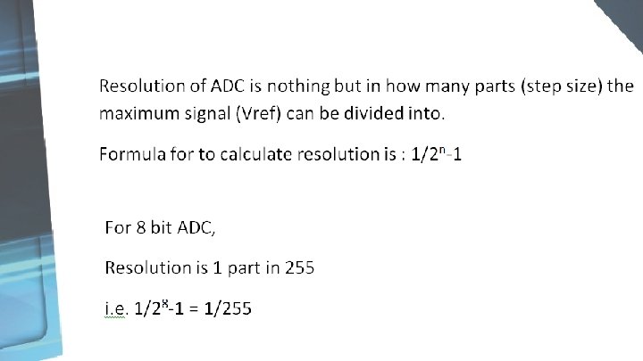

Resolution

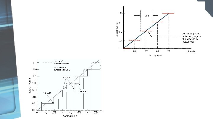
This table shows the Digital output of 3 bit ADC corresponding to Input Voltage in the range between 0 to 1 V. Analog Input Digital Output 0 V 0 0. 143 V 0 0 1 0. 286 V 0 1 0 0. 429 V 0 1 1 0. 572 V 1 0 0 0. 715 V 1 0. 858 V 1 1 0 1. 001 V 1 1 1

Pin Description of 0571 ADC IC IC 0571 ADC

0571 ADC interfacing with 8051 Microcontroller Circuit

Algorithm Apply input to analog terminal Give Clear pulse to BLANK/ ¯C to start conversion by sending low through P 3. 0 How ? think Image 2 Polls until P 3. 1= 0 i. e until (DR) become low to indicate End of conversion When data is ready, read the LB of digital output through port 1 and copy in the Accumulator, and HB of the digital output through port 2 and copy in Reg. B. Repeat the same algorithm for next conversion.

Ans: - By using SETB P 3. 0 and CLR P 3. 0 instruction introduce delay in between. The Code ORG 00 H MOV P 1, #0000 B // initiates P 1 as the input port MOV P 2, #0000 B // initiates P 2 as the input port MAIN: SETB P 3. 1// makes (DR) is High SETB P 3. 0// makes B/(C ) is High CAll delay //short delay CLR P 3. 0// makes B/(C ) is low so as to have high to low pulse clear pulse for start of conversion WAIT: JB P 3. 1, WAIT // polls until P 3. 1= 0 i. e until (DR) become low to indicate End of conversion MOV A, P 1 // moves lower order digital data to accumulator MOV B, P 2 // moves Higher order digital data to Reg. B SJMP MAIN // jumps back to the MAIN program END

Assignment Interface ADC 0751 with 8051 microcontroller. Write program to convert Analog voltage into digital value. Find out resolution of ADC 0751. For each digital o/p, compare observed analog voltage with ideally calculated analog value

References Microcontroller, Ajay Deshmukh, 1 st Edition, Tata Mcgraw Hill 8051 & Embedded C programming, Mazidi, 2 nd Edition , Person Education
 Head, Department of Electronics D. B. Science")
Presented by Dr. Jayant Mahakhode (jayantmahakhode@gmail. com) Head, Department of Electronics D. B. Science College, Gondia. 441614
- Slides: 16