Microcontroller DKT 225 Interrupt INTRODUCTION An interrupt is
 Interrupt")


 • For every interrupt, there must be an interrupt service")


, all interrupt vectors")


 REGISTER")


- Slides: 44
Microcontroller (DKT 225) Interrupt
INTRODUCTION • An interrupt is “The occurrence of an event that causes a temporary suspension of a current program while the event is serviced by another program – Interrupt Service Routine (ISR)” • The event occurs at intervals unpredictable or uncontrolled by software • After execution of the ISR, the program resumes where it left off • Allow a system to respond asynchronously to an event and deal with the event while another program is executing.
INTRODUCTION • An interrupt driven system gives the illusion of doing many things simultaneously. – Not all at the same time – Based on the priority assigned to it • Of course, the CPU cannot execute more than one instruction at a time. • It can temporarily suspend execution of one program, execute another, then return to the first program. • In a way, interrupts are like subroutines. Except that one does not know when the interrupt code will be executed.
INTERRUPT VS POLLING • Polling - CPU monitors all served devices continuously, looking for a “service request flag” - CPU asks the devices periodically whether they need a service - Whenever it sees a request, it serves the device and then keeps polling - CPU is always “busy” with polling doing the “while any request” loop eg. LOOP: JNB TF 0, LOOP - Waste CPU’s processing power & time Device #1 Ready Service Routine #1 Device #2 Ready Service Routine #2
INTERRUPT VS POLLING • Interrupts - If and when a device is ready and needs attention, it informs the CPU - The device notify microcontroller by sending interrupt signal - CPU drops whatever it was doing and serves the device and then returns back to its original task - CPU is always “free”, when not serving any interrupts MAIN Interrupt Service Routine
INTERRUPTS VS POLLING • The advantage of interrupts is that the microcontroller can serve many devices (not all at the same time) - Each devices can get the attention of the microcontroller based on the assigned priority - For the polling method, it is not possible to assign priority since it checks all devices in a round-robin fashion • The microcontroller can also ignore (mask) a device request for service - This is not possible for the polling method
Interrupt service routine (ISR) • For every interrupt, there must be an interrupt service routine (ISR), or interrupt handler - When an interrupt is invoked, the microcontroller runs the interrupt service routine - For every interrupt, there is a fixed location in memory that holds the address of its ISR - The group of memory locations set aside to hold the addresses of ISRs is called interrupt vector table - ISRs are basically “subroutines”, but they end with the RETI, instruction instead of RET - When an interrupt occurs, the CPU fetches its ISR code address from the IVT and executes it.
EXECUTING AN INTERRUPT Upon activation of an interrupt, the microcontroller goes through the following steps: 1. It finishes the instruction it is executing and saves the address of the next instruction (PC) on the stack 2. It also saves the current status of all the interrupts internally (i. e: not on the stack) 3. It jumps to a fixed location in memory, called the interrupt vector table, that holds the address of the ISR
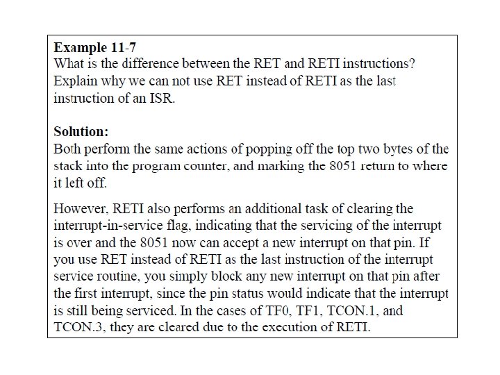
EXECUTING AN INTERRUPT 4. The microcontroller gets the address of the ISR from the interrupt vector table and jumps to it - It starts to execute the interrupt service subroutine until it reaches the last instruction of the subroutine which is RETI (return from interrupt) 5. Upon executing the RETI instruction, the microcontroller returns to the place where it was interrupted - First, it gets the program counter (PC) address from the stack by popping the top two bytes of the stack into the PC - Then it starts to execute from that address
INTERRUPTS IN 8051 • Reset - power-up reset • External Interrupts (INT 0 & INT 1) - for external hardware interrupts - or EX 1 & EX 2 • Timer Interrupts T 0 & T 1 - For timer 0 and timer 1 • Serial Communication Interrupt - Single interrupt that belongs to both receive and transfer
INTERRUPTS IN 8051 • Interrupt Vector Table
INTERRUPTS IN 8051 • Based on the Interrupt Vector Table (IVT), all interrupt vectors are at the beginning of code memory. The main program may begin at address 0030 H or after, if any interrupt were used
INTERRUPTS IN 8051 • Limited number of bytes is set aside for each interrupt – 8 bytes of space for every interrupt • If the service routine for an interrupt (ISR) is short enough to fit in the memory space allocated to it, it is placed in the vector table • Otherwise, LJMP instruction is placed in the corresponding vector table to redirect the ISR to other place in code memory • In that case, the rest of the bytes allocated to the interrupt will be unused
ENABLE/DISABLE INTERRUPT • Upon reset, all interrupts are disabled (none will be responded to by the microcontroller if they are activated) • Interrupts can be individually enabled or disabled by software • This is done in the IE (Interrupt Enable) register • IE is bit addressable (1 =Enable, 0 =Disable) • All interrupts correspond to bits in registers. • Therefore, it is possible to cause an interrupt by setting the appropriate bit in the appropriate register
INTERRUPT ENABLE (IE) REGISTER
ENABLE/DISABLE INTERRUPT
ENABLE/DISABLE INTERRUPT
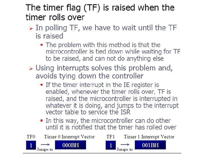
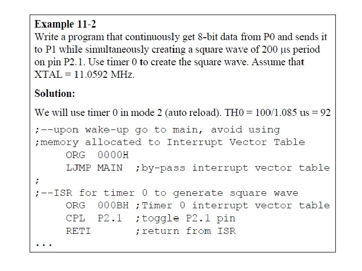
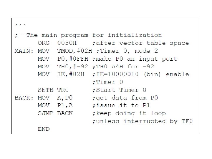
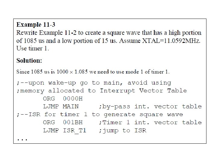
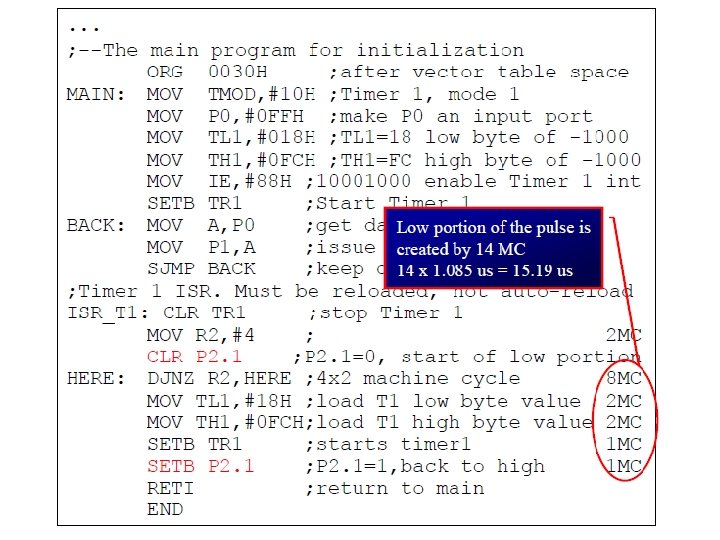
PROGRAMMING TIMER INTERRUPTS • Timer port interrupts: Timer 0 & Timer 1 – Pin 14 (P 3. 4) and Pin 15 (P 3. 5) • Timer port interrupts are generated by the timer interrupt flags TF 0 & TF 1 • Interrupt flags are set when their respective timer/counter registers rollover from all 1 s to all 0 s • When CPU vectors to a timer ISR, on-chip hardware in 8051 clears the interrupt flag that generates the interrupt – For timing operation without using interrupt, these timing interrupts flags have to be cleared by software (CLR TFx)
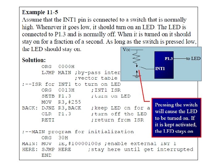
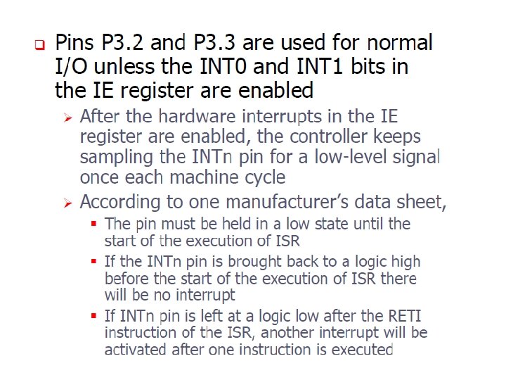
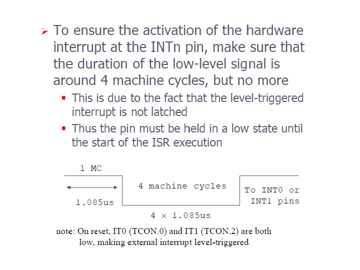
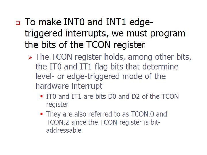
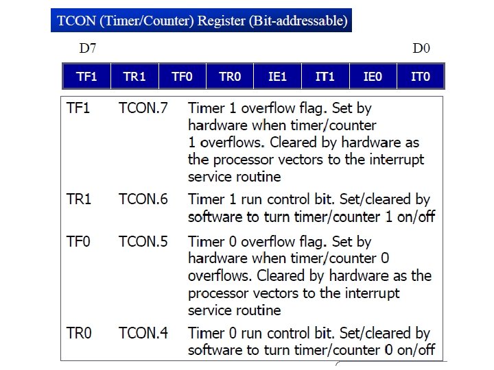
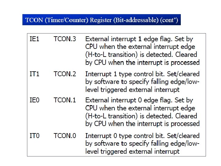
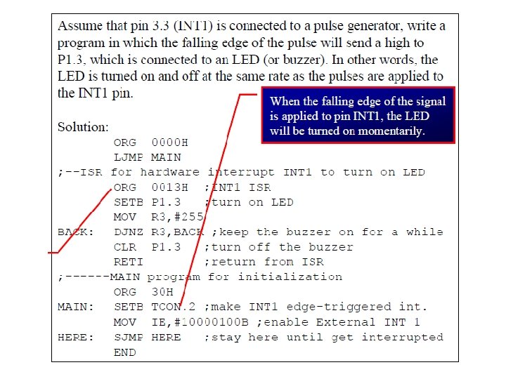
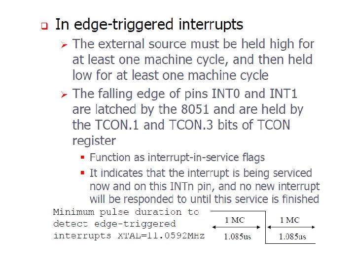
PROGRAMMING EXTERNAL INTERRUPTS • External hardware interrupts: INT 0 & INT 1 – Pin 12 (P 3. 2) and Pin 13 (P 3. 3) • Upon activation, 8051 gets interrupted in whatever it is doing and jumps to vector table to perform ISR • Enable/disable using IE Register • Activation through level triggered or edge triggered based on bits IT 0 and IT 1 in the TCON register • For level-triggered (ITx = 0, default), a low on the pin causes an interrupt. • For edge-triggered (ITx = 1), a high-to-low transition causes the interrupt
PROGRAMMING EXTERNAL INTERRUPTS
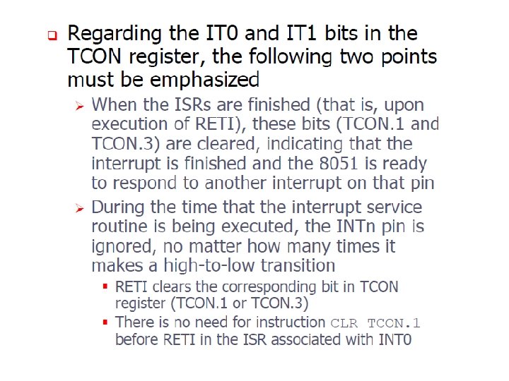
PROGRAMMING EXTERNAL INTERRUPTS • Level-triggered Interrupt – Active low. A low-level signal has to be applied to the external interrupt pin in order to trigger interrupt – The low-level signal at the INT pin must be removed before execution of RETI, or else another interrupt will be generated • Edge-triggered Interrupt – When a high-to low signal applied to INT 0, INT 1 pin, IE 0, IE 1 bits will be set, 8051 will be interrupted and forced to jump to vector table to perform ISR – While executing ISR, no H-to-L pulse transition on INT 0/INT 1 is recognized – preventing any interrupt inside interrupt – After execution RETI, IE bit automatically cleared
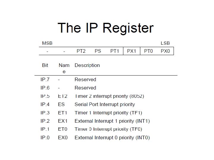
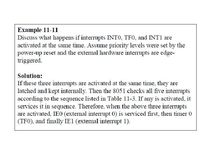
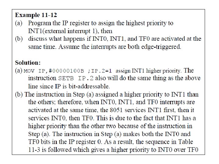
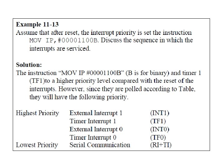
INTERRUPT PRIORITY • 8051 implements 2 types of interrupt priority. • User Defined Priority. – Using the IP register, the user can group interrupts into two levels – high and low – An interrupt is assigned a “high” priority level by setting its bit in the IP register to 1. If the bit is set to 0, the interrupt gets a “low” priority • Automatic Priority. – Within each priority level, a strict order is observed – Interrupts are ordered as follows: INT 0, TF 0, INT 1, TF 1, SO
AUTOMATIC PRIORITY • Internal Polling Sequence – to determine which request to service first • Within each priority level, there’s second priority structure which is determined by the fixed polling sequence
USER DEFINED PRIORITY • Upon system reset, IP contains all 0 s which means all the interrupts are at low priority level • When a low priority interrupt is being serviced, it can be interrupted by a high priority interrupt but not by another low priority interrupt • No interrupt source whether high/low priority can interrupt a high priority interrupt source • When two or more interrupt bits in IP Register are set to high, while these interrupts have a higher priority than others, they are serviced according to the sequence table