DMT 245 Introduction to Microcontroller Chapter 2 8051


 There are 4 arithmetic flags in the 8051 Carry (C)")
 u u u u C AC -RS 1 RS 0")


 or decrement (DEC) the internal memory")


 and the higher-nibble (upper 4")


 continuously")

 Register addressing (eg. MOV A,")


 Program memory 10 Addresses 200 ACC")


 MOV MOV MOV A, #55 h 40 h, A")
 register indirect addressing mode without a loop MOV A,")
 MOV MOV AGAIN: MOV INC DJNZ Loop method A,")
 Write a program segment to clear 15 RAM locations starting")
 Write a program segment to copy a block of")

 and an offset (how much to")


 Write a program to get the x value from")
 instructions Relative address: an 8 -bit value (-128")


- Slides: 74
DMT 245 Introduction to Microcontroller │ Chapter 2 │ 8051 Assembly Language Programming (part 2)
In this Lecture …… Arithmetic instructions Logical instructions Rotate instructions Comparison instructions Various 8051 addressing modes Read textbook pages : P. 96 - P. 107
Arithmetic Instructions There are 24 arithmetic opcodes which are grouped into the following types: ADD and ADDC SUBB MUL DIV INC DEC DA
Arithmetic Flags Flag: It is a 1 -bit register that indicates the status of the result from an operation Flags are either at a flag-state of value 0 or 1 Arithmetic flags indicate the status of the results from mathematical operations ( +, , *, / )
Arithmetic Flags (Conditional Flags) There are 4 arithmetic flags in the 8051 Carry (C) Auxiliary Carry (AC) Overflow (OV) Parity (P) All the above flags are stored in the Program Status Word (PSW) C AC -- RS 1 RS 0 OV -- P PSW. 7 PSW. 6 PSW. 5 PSW. 4 PSW. 3 PSW. 2 PSW. 1 PSW. 0
Arithmetic Flags (Conditional Flags) u u u u C AC -RS 1 RS 0 0 V -P PSW. 7 PSW. 6 PSW. 5 PSW. 4 PSW. 3 PSW. 2 PSW. 1 PSW. 0 Carry flag Auxiliary carry flag Available to the user for general purpose Register Bank selector bit 1 Register Bank selector bit 0 Overflow flag User definable flag Parity flag *The C flag is keeping track in unsigned operations *The OV flag is keeping track in signed operations
Instructions that Affecting Flags Instruction Mnemonic ADDC SUBB MUL DIV DA A SETB C MOV C, bit (1/2) Flags Affected C C=0 C C=1 C AC AC AC OV OV OV
Instructions that Affecting Flags Instruction Mnemonic ORL C, bit ANL C, bit RLC RRC CLR C CPL C CJNE (2/2) Flags Affected C C C=0 C = /C C
The ADD and ADDC Instructions ADDC A, source ; A = A + source + C A register must be involved in additions The C flag is set to 1 if there is a carry out of bit 7 The AC flag is set to 1 if there is a carry out of bit 3 ADD is used for ordinary addition ADDC is used to add a carry after the LSB addition in a multi-byte process
Example 6 -1 Show the flag register is affected by the following instructions. MOV A, #0 F 5 h ; A = F 5 h ADD A, #0 Bh ; A = F 5 + 0 B = 00 Solution F 5 h 1111 0101 + 0 Bh + 0000 1011 100 h 1 0000 After the addition, register A (destination) contains 00 and the flags are as follows: C = 1 since there is a carry out from D 7 P = 0 because the number of 1’s is zero AC = 1 since there is a carry from D 3 to D 4
Extra notes Rules of Binary Addition 0 + 0 = 0 0 + 1 = 1 1 + 0 = 1 1 + 1 = 0, and carry 1 to the next more significant bit
Extra notes Rules of Binary Subtraction 0 - 0 = 0 0 - 1 = 1, and borrow 1 from the next more significant bit 1 - 0 = 1 1 - 1 = 0
Example 6 -2 Assume that RAM locations 40 h - 42 h have the following values. [RAM locations: 40 h = (7 Dh), 41 h = (EBh), 42 h = (C 5 h)] Write a program to find the sum of the values in these locations. At the end of the program, register A should contain the low byte and R 7 contain the high byte. Solution: NEXT 1: MOV ADD JNC INC END A, 40 h R 7, #0 A, 41 h NEXT R 7 A, 42 h NEXT 1 R 7 ; ; ; ; set A = RAM location 40 h set R 7 = 0 add A with RAM location 41 h if CY = 0 don’t accumulate carry keep track of carry add A with RAM location 42 h if CY = 0 don’t accumulate carry keep track of carry
Example 6 -3 Write a program segment to add two 16 -bit numbers. The numbers are 3 CE 7 h and 3 B 8 Dh. Place the sum in R 7 and R 6; R 6 should store the lower byte. CLR MOV ADDC MOV C ; make C=0 A, #0 E 7 h ; load the low byte now A=E 7 h A, #8 Dh ; add the low byte now A=74 h and C=1 R 6, A ; save the low byte of the sum in R 6 A, #3 Ch ; load the high byte A, #3 Bh ; add with the carry ; 3 B + 3 C + 1 = 78 (all in hex) R 7, A ; save the high byte of the sum
The DA Instruction ADDC …. . DA A ADD …. . DA A Ø The action is to “decimal adjust” the register A Ø Used after the addition of two BCD numbers Example 6. 4 : MOV A, #47 h ; A=47 h first BCD operand MOV ADD B, #25 h A, B ; B=25 h second BCD operand ; hex (binary) addition (A=6 Ch) DA A ; adjust for BCD addition (A=72 h)
Example 6. 4 of DA Instruction Hex 47 + 25 6 C + 6 72 Offset decimal 6 ! BCD 0100 0111 + 0010 0101 0110 1100 + 0110 0111 0010
The SUBB Instruction SUBB A, source SUBB A, #data A, direct A, @Ri , where i =0 or 1 A, Rn, where n =0, 1, , 7 No borrow: A = A – source With borrow: A = A – source – carry (i. e. borrow) Note that the 8051 uses the 2’s complement method to do subtraction. After execution: The C flag is set to 1 if a borrow is needed into bit 7 The AC flag is set to 1 if a borrow is needed into bit 3
Extra notes Rules of Binary Subtraction 0 - 0 = 0 0 - 1 = 1, and borrow 1 from the next more significant bit 1 - 0 = 1 1 - 1 = 0
The MUL Instruction MUL AB Uses registers A and B as both source and destination registers Numbers in A and B are multiplied, then put the lower-order byte of the product in A and the highorder byte in B The OV flag is set to 1 if the product > FFh Note that the C flag is 0 at all times
The DIV Instruction DIV AB Similarly, it uses registers A and B as both source and destination registers The number in A is divided by B. The quotient is put in A and the remainder (if any) is put in B The OV flag is set to 1 if B has the number 00 h (divide -by-zero error) Note that the C flag is 0 at all times
The INC and DEC Instructions To increment (INC) or decrement (DEC) the internal memory location specified by the operand No change with all the arithmetic flags in this operation e. g. INC 7 Fh ; content in 7 Fh increased by 1 DEC R 1 ; content in R 1 decreased by 1 Others: INC A INC direct INC @Ri where i=0, or 1 INC Rn where n=0, 1, …, 7
Logic Operation in 8051 Logical operations Rotate and swap operations Comparison operations
General Logic Functions There are instructions available for the 8051 to implement the following logic functions AND OR XOR (exclusive-OR) NOT (invert/complement)
Logical Instructions ANL destination, source ANL ANL ANL direct, A direct, #data A, direct A, @Ri where i=0, or 1 A, Rn where n=0, , 7 Destination = destination AND source ORL destination, source Destination = destination OR source XRL destination, source Destination = destination XOR source Usually, the destination is register A or a direct address in the internal RAM
Logical Instructions The source operand can be any of the 4 addressing modes (i. e. immediate/register/ direct/indirect) ANL can be used to clear (0) certain bits ORL can be used to set (1) certain bits Examples
The CLR and CPL Instructions CLRA All bits in register A are cleared CPL A All bits in register A are complemented (inverted) Note that CLR and CPL instructions operate on register A only
The Rotate Instructions RL A RR A Contents in register A is rotated one bit position to the left or to the right (operated in A only) The bit shifted out is used as the new bit shifted in May include the C flag in the operation RLC A RRC A Useful in inspecting the bits in a byte one by one Also useful for multiplication and division in powers of 2
The Rotate Instructions RL A Rotates A one bit position to the left RLC A Rotates A and the carry flag one bit position to the left RR A Rotates A one bit position to the right RRC A Rotates A and the carry flag one bit position to the right *Note that for RLC and RRC, you have to know the C flag first
The Rotate Instructions
The SWAP Instruction Swapping the lower-nibble (lower 4 bits) and the higher-nibble (upper 4 bits) of register A. SWAP A Register A = 5 Eh (original value) after SWAP Register A = E 5 h
Comparison Operation CJNE – Compare and Jump if Not Equal CJNE destination, source, relative address Compare the source and destination operands first Jump to the relative address (subroutine) if they are not equal Carry flag = 1 if destination-byte is less than the source-byte, Otherwise, the carry flag is cleared = 0.
Comparison Operation CJNE A, #data, relative A, direct, relative @Ri, #data, relative Rn, #data, relative where i=0 or 1 where i=0, , 7 ; example !! COMPARE: CJNE R 7, #60 H, NOT_EQ ………………. . ; now R 7 = 60 H NOT_EQ: 60 H JC ; now C = 0, ie. R 7 > REG_LOW: ………………. . REG_LOW ………………. . ; now C = 1. ie. R 7 < 60 H
Example 6 -5 Write a program segment to monitor Port 1 (P 1) continuously for the value of 63 h. It should get out of the monitoring only if P 1 = 63 h. Solution : MOV P 1, #0 FFh ; make P 1 an input port HERE: MOV A, P 1 ; get P 1 CJNE A, #63 h, HERE ; keep monitoring P 1 ; unless P 1=63 h
Addressing Modes Addressing mode: a method that… Points out where the operands (i. e. source and destination) are, and How these operands should be accessed The opcode in an instruction specifies what addressing mode will be used
Addressing Modes Immediate addressing (eg. MOV A, #55 H) Register addressing (eg. MOV A, R 0) Direct addressing (eg. MOV A, 30 H) Register indirect addressing (eg. MOV A, @R 0) Indexed addressing (eg. MOVC A, @A+PC) Absolute addressing (eg. ACALL address 11) Long addressing (eg. LCALL addr 16 ) Relative addressing (Eg. SJMP relative)
Immediate Addressing Source operand is a constant number/character – “immediate data” If the operand is a number, we must add a “#” sign before it e. g. ADD A, #56 h ; add 56(16) to the number in register A e. g. MOV R 6, #81 ; load 81(10) into R 6 Applications: e. g. initialize a number of registers to zero; overwrite a constant character
Examples of Immediate Addressing
Notes of Immediate Addressing Add “#” before any immediate data Only the source operand can be immediate Add “h” after a base-16 number, “b” after a base-2 number; otherwise assumed base-10 Use ‘ ’ to enclose any character Precede all base-16 numbers that begin with A-F by a “ 0” MOV A, #ABh
Register Addressing Source/destination/both of them are registers located in the CPU registers (i. e. R 0 – R 7; A; DPTR) e. g. MOV A, R 5 e. g. MOV R 3, A e. g. ADD A, R 2 e. g. MOV R 7, DPL MOV R 6, DPH ; copy the contents of R 5 into A ; copy the contents of A into R 3 ; add the contents of R 2 to contents of A
Notes of Register Addressing The most efficient addressing mode: No need to do memory access Instructions are much shorter Result: speed (hence efficiency) increased We can move data between Acc and Rn (n = 0 to 7) but movement of data between Rn registers is not allowed e. g. MOV R 4, R 7 (Invalid)
Review Questions 1. Can the programmer of a microcontroller make up new addressing modes? 2. Show the instruction to load 1000 0000 (binary) into R 3. 3. Why is the following invalid? “MOV R 2, DPTR” 4. True or false. DPTR is a 16 -bit register that is also accessible in low-byte and high-byte formats. 5. Is the PC (program counter) also available in low-byte and high-byte formats?
Direct Addressing Source/destination/both of them are specified by an 8 -bit address field in the instruction Use this mode to access the 128 bytes of RAM and the SFR (Table 5 -1, textbook P. 100) Location of operand is fixed cannot be changed when program is running, but content can be changed Inflexible to address elements in a table of data
Examples of Direct Addressing MOV direct, direct Note: No “#” sign in the instruction
Examples of Direct Addressing MOV R 2, #5 ; R 2 = 05 MOV A, 2 ; copy location 02 (R 2) to A MOV B, 2 ; copy location 02 (R 2) to B MOV 7, 2 ; copy location 02 to 07 (R 2 to R 7) ; since “MOV R 7, R 2” is invalid MOV direct, direct
Stack and Direct Addressing Mode Only direct addressing mode is allowed for pushing onto the stack PUSH A (Invalid) PUSH 0 E 0 h (Valid) PUSH R 3 (Invalid) PUSH 03 (Valid) POP R 4 (Invalid) POP 04 (Valid) PUSH direct POP direct
Example 6 -6 Show the code to push R 5, R 6, and A onto the stack and then pop them back into R 2, R 3, and B, where register B = register A, R 2 = R 6, and R 3 = R 5. Solution : PUSH 05 PUSH 06 PUSH 0 E 0 h POP 0 F 0 h POP 02 POP 03 ; ; ; ; ; push R 5 onto stack push R 6 onto stack push register A onto stack pop top of stack into register B now register B = register A pop top of stack into R 2 now R 2 = R 6 pop top of stack into R 3 now R 3 = R 5
Notes of Direct Addressing The address value is limited to one byte, 00 – FFh (128 -byte RAM and SFR) Using MOV to move data from itself to itself can lead to unpredictable results error MOV A, A MOV data to a port changes the port latch MOV data from port gets data from port pins
Register Indirect Addressing Use a register to hold the address of the operand; i. e. using a register as a pointer Only R 0 and R 1 can be used when data is inside the CPU (address ranges from 00 h – 7 Fh) e. g. MOV A, @R 1 R 0 , R 1 and DPTR can be used when addressing e. Xternal memory locations eg. MOVX A, @R 1 MOVX A, @DPTR Must put a “@” sign before the register name
Register Indirect Addressing (eg. ADD A, @R 0) Program memory 10 Addresses 200 ACC ADD A, @R 0 201 ACC 22 R 0 31 31 Before After Data memory 30 31 32 12
Examples of Indirect Addressing MOV @Ri, #data where i=0 or 1
Example 6 -7 Write a program segment to copy the value 55 h into RAM memory locations 40 h to 44 h using: (c) Direct addressing mode; (d) Register indirect addressing mode without a loop; (e) and with a loop
Solution to Example 6 -7(a) MOV MOV MOV A, #55 h 40 h, A 41 h, A 42 h, A 43 h, A 44 h, A Direct addressing mode ; load A with value 55 h ; copy A to RAM location 40 h ; copy A to RAM location 41 h ; copy A to RAM location 42 h ; copy A to RAM location 43 h ; copy A to RAM location 44 h
Solution to Example 6 -7(b) register indirect addressing mode without a loop MOV A, #55 h ; load A with value 55 h MOV INC MOV R 0, #40 h @R 0, A R 0 @R 0, A ; load the pointer. R 0 = 40 h ; copy A to RAM location R 0 points to ; increment pointer. Now R 0 = 41 h ; copy A to RAM location R 0 points to ; increment pointer. Now R 0 = 42 h ; copy A to RAM location R 0 points to ; increment pointer. Now R 0 = 43 h ; copy A to RAM location R 0 points to ; increment pointer. Now R 0 = 44 h ; copy A to RAM location R 0 points to
Solution to Example 6 -7(c) MOV MOV AGAIN: MOV INC DJNZ Loop method A, #55 h ; A = 55 h R 0, #40 h R 2, #05 @R 0, A R 0 R 2, AGAIN ; load pointer. R 0 = 40 h, RAM address ; load counter, R 2 = 5 ; copy A to RAM location pointed by R 0 ; increment pointer R 0 ; loop until counter = zero MOV R 2, #05 h ; example LP: ; ----------------; do 5 times inside the loop ; ----------------DJNZ R 2, LP ; R 2 as counter “DJNZ” : decrement and jump if Not Zero DJNZ direct, relative DJNZ Rn, relative where n = 0, 1, , , 7
Example 6 -8 (looping) Write a program segment to clear 15 RAM locations starting at RAM address 60 h. CLR MOV AGAIN: MOV INC DJNZ A R 1, #60 h R 7, #15 @R 1, A R 1 R 7, AGAIN ; A=0 ; load pointer. R 1 = 60 h ; load counter, R 7 = 15 (0 F in HEX) ; clear RAM location R 1 points to ; increment R 1 pointer ; loop until counter = zero ; clear one ram location at address 60 h CLR A MOV R 1, #60 h Setup a loop using DJNZ and register R 7 as counter MOV @R 1, A
Example 6 -9 (block transfer) Write a program segment to copy a block of 10 bytes of data from RAM locations starting at 35 h to RAM locations ; COPY 1 TIMES MOV R 0, #35 h starting at 60 h. MOV R 1, #60 h MOV A, @R 0 MOV @R 1, A BACK: MOV MOV R 0, #35 h R 1, #60 h R 3, #10 MOV A, @R 0 MOV @R 1, A INC R 0 INC R 1 DJNZ R 3, BACK ; source pointer ; destination pointer ; counter ; get a byte from source ; copy it to destination ; increment source pointer ; increment destination pointer ; keep doing it for all ten bytes
Notes of Indirect Addressing Using pointer in the program enables handling dynamic data structures an advantage Dynamic data: the data value is not fixed In this mode, we can defer the calculation of the address of data and the determination of the amount of memory to allocate at (program) runtime Register or direct addressing (eg. MOV A, 30 H) cannot be used , since they require operand addresses to be known at assemble-time.
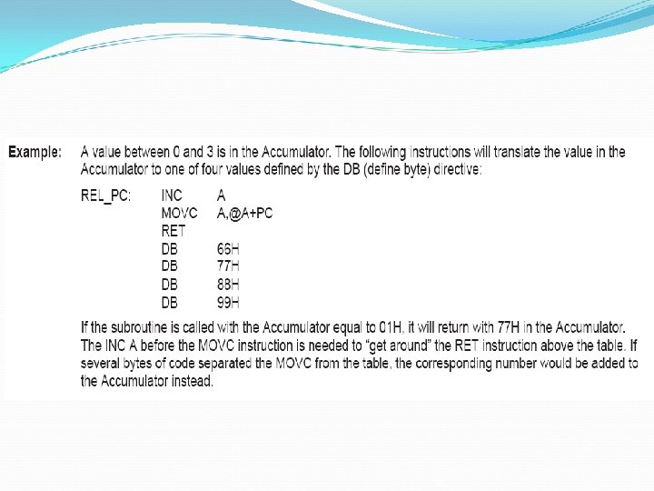
Indexed Addressing Using a base register (starting point) and an offset (how much to parse through) to form the effective address for a JMP or MOV instruction Used to parse through an array of items or a lookup table Usually, the DPTR is the base register and the “A” is the offset A increases/decreases to parse through the list MOVC A, @A+DPTR MOVC A, @A+PC JMP @A+DPTR
Indexed Addressing Program memory 00 Example: MOVC A, @A+DPTR ACC 10 ACC 56 DPTR 41 56 31 Before 2000 2001 MOVC A, @A + DPTR After
Examples of Indexed Addressing
Example 6 -10 (look-up table) Write a program to get the x value from P 1 and send x 2 to port P 2, continuously. BACK: TABLE: ORG MOV MOV MOV SJMP 0 DPTR, #300 h A, #0 FFh P 1, A A, P 1 A, @A+DPTR P 2, A BACK ORG DB END 300 h 0, 1, 4, 9, 16, 25, 36, 49, 64, 81 ; load look-up table address ; A = FF ; configure P 1 as input port ; get X square from table ; issue it to port P 2 ; keep doing it
Relative Addressing Used in jump (“JMP”) instructions Relative address: an 8 -bit value (-128 to +127) You may treat relative address as an offset Labels indicate the JMP destinations (i. e. where to stop) Assembler finds out the relative address using the label SJMP relative DJNZ direct, relative DJNZ Rn, relative where n=0, 1, , , 7
Relative Addressing The relative address is added to the PC The sum is the address of the next instruction to be executed As a result, program skips to the desired line right away instead of going through each line one by one Labels indicate the JMP destinations (i. e. where to stop).
Relative Addressing Branch Opcode Program Counter Offset Next Opcode + Offset Program counter + offset = Effective address = address of next instruction Next Instruction
Examples of Relative Addressing 0035
Absolute Addressing ACALL addressing AJMP addressing Only used with the instructions ACALL and AJMP Similar to indexed addressing mode The largest “jump” that can be made is 2 K 211 = 2048=2 K Long Addressing Only used with the instructions LCALL and LJMP Similar to indexed addressing mode The largest “jump” that can be made is 64 K
Absolute vs Long Addressing Absolute addressing: 11 -bit address in 2 -byte instruction Long addressing: 16 -bit address in 3 -byte instruction Range of the “jump” of long is greater than absolute Yet absolute mode has shorter code (2 bytes), hence faster execution
Why So Many Modes? There are many methods to do a task Some are more efficient while some are not Choosing the right addressing mode will enable us to finish the task efficiently Let’s take a simple case as example: “Clear the memory location from 30 h to 7 Fh. ” We can use MOV instruction in direct addressing mode to nullify these memory one by one But the program will be too lengthy and spaceconsuming
Why So Many Modes? So, we may try using indirect addressing mode like this: MOV 30 h, #00 h ; Clear Array [0] MOV 31 h, #00 h ; and Array [1]. ; Keep on going MOV R 0, #30 h ; Set up pointer to start of array clear_arr: MOV @R 0, #00 ; Clear target byte pointed to by R 0 . INC . CJNE R 0, #80 H, clear_arr ; Has pointer reached 80 MOV 7 Eh, #00 h ; Clear Array [78] MOV 7 Fh, #00 h ; Clear Array [79] Direct addressing mode uses up 240 bytes 5 x 16 x 3 = 240 Since 3 bytes for MOV direct, #data ? NEXT: R 0 . . . . ; Advance pointer by 1 ; if not over the top THEN again ELSE ; next instruction Indirect addressing mode uses up 8 bytes ONLY, with a saving of 232 bytes !
A Little Further …. . Yet, the program is still too long. A much better method would be writing a subroutine (= function in C programming) to do nullification Write a loop to call the subroutine for (7 F-30+1) times to nullify all memory As a result, we don’t have to write so many lines of program
Read reference The 8051 Microcontroller and Embedded Systems Using Assembly and C, Mazidi Ø Chapter 5 P. 109 – P. 135 Ø Chapter 6 P. 139 – P. 167
│ THE END │