DC motor interfacing with 8051 Basics of DC

DC motor interfacing with 8051

Basics of DC motor • widely used device that translates electrical pulses into mechanical movement. • has only + and – leads. • Connecting them to a DC voltage source moves the motor in one direction. • By reversing the polarity, the DC motor will move in the opposite direction.

Important parameters of DC motor • Voltage • Current • RPM

Unidirectional motor control

Bidirectional motor control
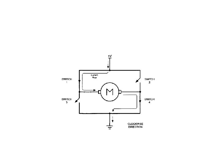
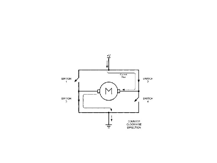
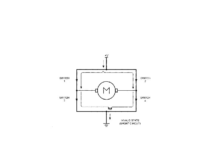

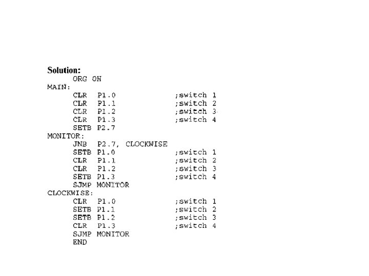
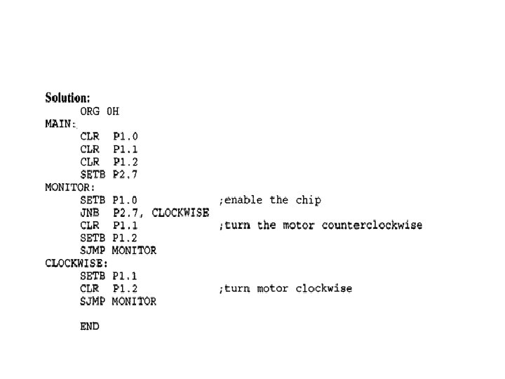
• A switch is connected to pin P 2. 7. Using a simulator, write a program to monitor the status of SW and perform the following: (i)If SW = 0, the DC motor moves clockwise. (ii) If SW = 1, the DC motor moves counterclockwise.

Bidirectional Motor Control Using an L 293 Chip
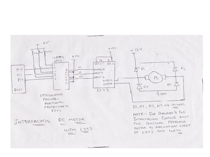

Example • Figure shows the connection of an L 293. Add a switch to pin P 2. 7. Write a program to monitor the status of SW and perform the following: (i)If SW = 0, the DC motor moves clockwise. (ii)If SW = 1, the DC motor moves counterclockwise.
with 8051")
Interfacing ADC(Analog to Digital Converter)with 8051
![• ADC 0808 has 3 control signals: SOC [Start of conversion]: When High](http://slidetodoc.com/presentation_image/6153b850daeb79c94d4c2c40ba036e83/image-16.jpg "• ADC 0808 has 3 control signals: SOC [Start of conversion]: When High")
• ADC 0808 has 3 control signals: SOC [Start of conversion]: When High to low signal is appeared to this pin of ADC, ADC then starts conversion. EOC [End of conversion]: ADC sends this high EOC signal to Micro. Controller to indicate completion of conversion. OE [Output Enable]: When a high signal is applied to this pin, The output latch of ADC get enables and the converted data is then available to Micro-Controller. • The reference voltage determines the range of analog input voltage. For example: - If reference voltage is 5 V then analog voltage range is from 0 V-5 V. If the reference voltage is 2. 56 V then the Analog signal range is from 0 V-2. 56 V. • The frequency of clock signal applied determines the conversion speed.

Interfacing diagram

LABEL OPCODE OPERAND SOC E 0 C OE ALE ADDR_C ADDR_B ADDR_A EQU P 2. 6 EQU P 2. 5 EQU P 2. 4 EQU P 2. 3 EQU P 2. 2 EQU P 2. 1 EQU P 2. 0 COMMENT

ORG MOV SETB CLR CLR 0000 H P 1, #0 FFH P 2. 5 SOC OE ALE

AGAIN: CLR CLR SETB ACALL CLR ADDR_C ADDR_B SOC ALE DELAY SOC ALE

BACK: HERE: AGAIN: JB JNB SETB MOV ACALL SJMP EOC BACK EOC HERE OE A, P 1 CONVERSION DISPLAY AGAIN

Interfacing DAC with 8051

Output current of DAC

Example •

Example In order to generate a stair-step ramp, set up the circuit in previous Figure and connect the output to an oscilloscope. Then write a program to send data to the DAC to generate a stair-step ramp.

- Slides: 26