4 fejezet Hlzati rteg A note on the


- Slides: 146

4. fejezet Hálózati réteg A note on the use of these ppt slides: We’re making these slides freely available to all (faculty, students, readers). They’re in Power. Point form so you can add, modify, and delete slides (including this one) and slide content to suit your needs. They obviously represent a lot of work on our part. In return for use, we only ask the following: q If you use these slides (e. g. , in a class) in substantially unaltered form, that you mention their source (after all, we’d like people to use our book!) q If you post any slides in substantially unaltered form on a www site, that you note that they are adapted from (or perhaps identical to) our slides, and note our copyright of this material. Computer Networking: A Top Down Approach 4 th edition. Jim Kurose, Keith Ross Addison-Wesley, July 2007. Thanks and enjoy! JFK/KWR All material copyright 1996 -2007 J. F Kurose and K. W. Ross, All Rights Reserved Hálózati réteg 1

4. fejezet: Hálózati réteg A fejezet célkitűzései: r értsük meg az elveket, amelyeken a hálózati réteg szolgáltatásai alapulnak: m hálózati réteg szolgáltatási modellek m továbbítás (forwarding) útvonalválasztás (routing) m hogyan működik egy router m routing (útvonalválasztás) m bővíthetőség (scale) m haladó téma: IPv 6, mobil r megvalósítás az Internet-ben Hálózati réteg 2

4. fejezet: Hálózati réteg r 4. 1 Bevezető r 4. 2 Virtuális áramkör és datagram hálózatok r 4. 3 Mi van egy routerben r 4. 4 IP: Internet Protokoll m m Datagram formátum IPv 4 címzés ICMP IPv 6 r 4. 5 Routing algoritmusok m Kapcsolat-állapot (Link state) m Távolságvektor m Hierarhikus routing r 4. 6 Routing az Internetben m RIP m OSPF m BGP r 4. 7 Broadcast és multicast routing Hálózati réteg 3

Hálózati réteg r szegmens szállítása a küldő r r host-tól a fogadóig a küldő fél datagramokba ágyazza be (encapsulate) a szegmenst a fogadó fél átadja a szegmenst a szállítási rétegnek hálózati réteg protokollok minden host-ban és routerben a router megvizsgálja minden rajta áthaladó IP datagram fejlécmezőit alkalmazás szállítás hálózat adatkapcs. fizikai hálózat adatkapcs. fiziaki hálózat adatkapcs fizikai hálózat adatkapcs. fizikai Hálózati réteg alkalmazás szállítás hálózat adatkapcs. fizikai 4

2 kulcsfontosságú hálózati réteg funkció r továbbítás (forwarding) : csomag átvitele a router bemenetéről a router megfelelő kimenetére r útvonalválasztás (routing): útvonal meghatározása, amelyet a csomag követ a forrástól a célig m Routing algoritmusok analógia: r útvonalválasztás: kirándulás megtervezése otthonról a célig r továbbítás: egy útkereszteződésen történő áthaladás Hálózati réteg 5

Útvonalválasztás és továbbítás közti kapcsolat útvonalválasztó algoritmus lokális forwarding tábla fejléc érték kimenő k. 0100 0101 0111 1001 3 2 2 1 érték az érkező csomag fejlécében 0111 1 3 2 Hálózati réteg 6

Kapcsolatteremtés r 3. fontos funkció egyes hálózati architektúrákban : m ATM, frame relay, X. 25 r a datagramok átvitele előtt a két host és az útvonalon levő routerek virtuális kapcsolatot teremtenek m a routerek szerepet kapnak r a hálózati és szállítási réteg kapcsolat-teremtési szolgáltatása m m hálózati réteg: két host között szállítási réteg: két folyamat között Hálózati réteg 7

Hálózati szolgáltatási modell K: Milyen szolgáltatási modellű a datagramokat a küldőtől a fogadóhoz szállító „csatorna”? Szolgáltatás példák egyes datagramokra: r garantált kézbesítés kevesebb, mint 40 ms késéssel Szolgáltatás példák datagram folyamokra: r sorrendhelyes datagram kézbesítés r garantált minimális sávszélesség r megkötések a csomagok közti távolság változására Hálózati réteg 8

Hálózati réteg szolgáltatási modellek: Hálózati architektúra Internet Szolg. modell Garantál? Sávsz. best effort nincs ATM CBR ATM VBR ATM ABR ATM UBR konstans sávsz. garantált minimum nincs Veszt. Sorrend Idő Torlódási visszajelzés nem nem igen igen nem(veszésből következtet) nincs torlódás igen nem nem Hálózati réteg 9

4. fejezet: Hálózati réteg r 4. 1 Bevezető r 4. 2 Virtuális áramkör és datagram hálózatok r 4. 3 Mi van egy routerben r 4. 4 IP: Internet Protokoll m m Datagram formátum IPv 4 címzés ICMP IPv 6 r 4. 5 Routing algoritmusok m m m Kapcsolat-állapot (Link state) Távolságvektor Hierarhikus routing r 4. 6 Routing az Internetben m m m RIP OSPF BGP r 4. 7 Broadcast és multicast routing Hálózati réteg 10

Hálózati réteg: kapcsolatalapú és kapcsolat nélküli szolgáltatások r a datagram hálózat kapcsolat nélküli hálózati réteg szolgáltatást biztosít r a virtuális áramkör (VC) hálózat kapcsolat-alapú hálózati réteg szolgáltatást biztosít r hasonló a szállítási réteg szolgáltatásaihoz, de: m szolgáltatás: host-tól host-ig m nincs választás: a hálózat csak egyiket „tudja” m implementálás: a hálózat magjában (core) Hálózati réteg 11

Virtuális áramkör „az útvonal a forrástól a célig hasonlóan viselkedik, mint egy telefonos áramkör” m m teljesítmény orientált hálózati tevékenységek az útvonalon a forrástól a célig r kapcsolatteremtés minden hívásra az adatáram kezdete előtt r minden csomag VC azonosítót hordoz (nem cél-host címet) r minden router a forrás-cél útvonalon nyilvántartja az „állapotát” minden rajta áthaladó kapcsolatnak r kapcsolat és router erőforrások (sávszélesség, pufferek) a virtuális áramkörnek oszthatók ki (dedikált erőforrások = megjósolható szolgáltatás) Hálózati réteg 12

VC implementáció Egy virtuális áramkör részei: 1. 2. 3. útvonal a forrástól a célig VC számok, egy szám az útvonal minden kapcsolatának forwarding tábla bemenetek az útvonalon levő routerekben r egy virtuális áramkörhöz tartozó csomag VC számot tartalmaz (nem a cél címét). r a VC szám megváltoztatható minden kapcsolaton. m az új VC szám a forwarding táblából származik Hálózati réteg 13

Forwarding tábla VC szám 22 12 1 Forwarding tábla a northwest routerben: Bemenő interfész 1 2 3 1 … Bemenő VC szám 12 63 7 97 … 2 32 3 interfész szám Kimenő interfész Kimenő VC szám 3 1 2 3 … 22 18 17 87 … A routerek megjegyzik a kapcsolat-állapot információkat Hálózati réteg 14

Virtuális áramkör: jelző protokollok r virtuális áramkör kapcsolatteremtésre, fenntartásra, bontásra használtak r ATM, frame-relay, X. 25 hálózatokban r a mai internetben nem használt alkalmazás szállítás 5. adatfolyam kezdete hálózat 4. kapcsolatban adatkapcs. 1. hívás kezdeményezés fizikai 6. adatok fogadása alkalmazás 3. hívás fogadása szállítás 2. bejövő hívás hálózat adatkapcs. fizikai Hálózati réteg 15

Datagram hálózatok r nincs kapcsolatteremtés a hálózati réteg szintjén r routerek: nincs állapotinformáció a végpontok közti kapcsolatokról m nincs „kapcsolat” fogalom a hálózati réteg szintjén r a csomagokat a cél címe szerint továbbítja m ugyanazon forrás-cél pár közötti csomagok különböző útvonalon haladhatnak alkalmazás szállítás hálózat adatkapcs. 1. adatküldés fizikai alkalmazás szállítás 2. adatfogadás network adatkapcs. fizikai Hálózati réteg 16

Forwarding tábla Cél címtartomány 4 milliárd lehetséges bemenet Kapcsolat interfész 11001000 00010111 00010000 – 11001000 00010111 1111 0 11001000 00010111 00011000 0000 – 11001000 00010111 00011000 1111 1 11001000 00010111 00011001 0000 – 11001000 00010111 00011111 2 különben 3 Hálózati réteg 17

Leghosszabb illeszkedő prefix Illeszkedő prefix 11001000 00010111 00010 11001000 00010111 00011000 11001000 00010111 00011 különben Kapcsolat interfész 0 1 2 3 Példa cím: 11001000 00010111 00010110 10100001 Melyik interfész? cím: 11001000 00010111 00011000 1010 Melyik interfész? Hálózati réteg 18

Datagram vagy VC hálózat: miért? Internet (datagram) r adatcsere számítógépek között „rugalmas” szolgáltatás, nem szükséges szigorú időzítés r „értelmes” végrendszerek (számítógépek) m képesek ellenőrzésre, hibajavításra, stb. m egyszerű a hálózat belseje, komplexitás a peremén r sokféle összekapcsoló közeg m különböző jellemzők m nehéz az egységes szolgáltatás megvalósítása m ATM (VC) r a telefonhálózatból fejlődött r (emberi) beszélgetés: szigorú időzítés, megbízhatóság szükséges m garantált szolgáltatás r „buta” végrendszerek m telefonok m komplexitás a hálózat magjában m Hálózati réteg 19

4. fejezet: Hálózati réteg r 4. 1 Bevezető r 4. 2 Virtuális áramkör és datagram hálózatok r 4. 3 Mi van egy routerben r 4. 4 IP: Internet Protokoll m m Datagram formátum IPv 4 címzés ICMP IPv 6 r 4. 5 Routing algoritmusok m m m Kapcsolat-állapot (Link state) Távolságvektor Hierarhikus routing r 4. 6 Routing az Internetben m m m RIP OSPF BGP r 4. 7 Broadcast és multicast routing Hálózati réteg 20

Router architektúra áttekintés Két fő funkció: r útvonalválasztó (routing) algoritmusok/protokollok futtatása (RIP, OSPF, BGP) r datagramok továbbítása a bemenő kapcsolatról a kimenőre Hálózati réteg 21

Bemenő port funkciók Fizikai réteg: bit-szintű fogadás Adatkapcsolati réteg: pl. Ethernet lásd 5. fejezet Decentralizált kapcsolás: r a datagrambeli cél cím alapján a bemenő port memóriájában levő forwarding táblában megkeresi a kimenő port számát r cél: bemenő portbeli feldolgozás „vonal sebességgel” r sorakozás: ha a datagramok gyorsabban érkeznek, mint a kapcsolómezőbe továbbítás sebessége Hálózati réteg 22

A kapcsolómező (switching fabric) 3 típusa Hálózati réteg 23

Memórián keresztüli kapcsolás Első generációs routerek: r megszokott számítógépek, kapcsolás a CPU vezérlésével r a csomagot a rendszer memóriájába másolja r a sebességet korlátozza a memória sávszélessége (2 sínhasználat datagramonként) Bemenő port Memória Kimenő port Rendszer sín Hálózati réteg 24

Sínen keresztüli kapcsolás r a datagram a bemenő port memóriájából egy osztott sínen jut a kimenő port memóriájába r versengés a sínért: a kapcsolás sebességét a sín sávszélessége korlátozza r 32 Gbps sín, Cisco 5600: megfelelő sebesség hozzáférési és vállalati routereknek Hálózati réteg 25

Összekötő hálózaton (interconnection network) keresztüli kapcsolás r a sín sávszélessége okozta korlátozás kiküszöbölése r Banyan hálózatok, más, eredetileg multiprocesszoros rendszerekben processzorok összekapcsolásához fejlesztett összekötő hálózatok r fejlett : datagramok fix hosszúságú cellákra osztása, cellák továbbítása a kapcsolómezőn keresztül. r Cisco 12000: 60 Gbps-al továbbít az összekötő hálózaton keresztül Hálózati réteg 26

Kimenő portok r Buffering required when datagrams arrive from fabric faster than the transmission rate r Scheduling discipline chooses among queued datagrams for transmission Hálózati réteg 27

Output port queueing r buffering when arrival rate via switch exceeds output line speed r queueing (delay) and loss due to output port buffer overflow! Hálózati réteg 28

How much buffering? r RFC 3439 rule of thumb: average buffering equal to “typical” RTT (say 250 msec) times link capacity C m e. g. , C = 10 Gps link: 2. 5 Gbit buffer r Recent recommendation: with N flows, buffering equal to RTT. C N Hálózati réteg 29

Input Port Queuing r Fabric slower than input ports combined -> queueing may occur at input queues r Head-of-the-Line (HOL) blocking: queued datagram at front of queue prevents others in queue from moving forward r queueing delay and loss due to input buffer overflow! Hálózati réteg 30

4. fejezet: Hálózati réteg r 4. 1 Bevezető r 4. 2 Virtuális áramkör és datagram hálózatok r 4. 3 Mi van egy routerben r 4. 4 IP: Internet Protokoll m m Datagram formátum IPv 4 címzés ICMP IPv 6 r 4. 5 Routing algoritmusok m m m Kapcsolat-állapot (Link state) Távolságvektor Hierarhikus routing r 4. 6 Routing az Internetben m m m RIP OSPF BGP r 4. 7 Broadcast és multicast routing Hálózati réteg 31

Az Internet hálózati rétege Hosztok, routerek hálózatiüréteg funkciói: Szállítási réteg: TCP, UDP Hálózati réteg IP protokoll • címzési konvenciók • datagramm formátuma • csomagkezelési konvenciók Útválasztó protokollok • útvonal választás • RIP, OSPF, BGP forwarding tábla ICMP protokoll • hiba jelentése • router „jelentkezése” Adatkapcsolati réteg fizikai réteg Hálózati réteg 32

4. fejezet: Hálózati réteg r 4. 1 Bevezető r 4. 2 Virtuális áramkör és datagram hálózatok r 4. 3 Mi van egy routerben r 4. 4 IP: Internet Protokoll m m Datagram formátum IPv 4 címzés ICMP IPv 6 r 4. 5 Routing algoritmusok m m m Kapcsolat-állapot (Link state) Távolságvektor Hierarhikus routing r 4. 6 Routing az Internetben m m m RIP OSPF BGP r 4. 7 Broadcast és multicast routing Hálózati réteg 33

IP datagramm formátuma IP protokoll verzió száma fejléc fossza (byte-ok) adat „típusa” hátralevő „lépések” max. száma (csökkenti minden router) 32 bit ver head. type of len service length fragment 16 -bit identifier flgs offset time to upper header layer live checksum fölötte levő réteg protokollja mennyi a datagramm hossza? r 20 byte TCP fejrész r 20 byte IP fejrész r = 40 byte + alk. réteg adatai datagramm teljes hossza (byte-oks) fragmentálás /összerakás 32 bit source IP address 32 bit destination IP address Options (if any) data (variable length, typically a TCP or UDP segment) Pl. időpecsét, útvonal, érintendő routerek listaja. Hálózati réteg 34

IP fragmentálás & összerakás r hálózati kapcsolatokra jellemző a maximális átviteli méret (MTU) – egy adatkapcsolati-réteg keret maximális mérete. m különböző kapcsolattípus, különböző MTU r nagy IP datagramot felossza („fragmentálja”) a hálózat m egy datagrammból több datagramm lesz m csak a célgépen „rakja össze” m IP fejléc biteket használ a fragmentumok azonosítására, sorrend megállapítására fragmentálás: be: egy nagy datagramm ki: 3 kisebb datagramm összerakás Hálózati réteg 35

IP fragmentálás & összerakás Példa r 4000 byte-os datagramm r MTU = 1500 byte 1480 byte az adatmezőben offset = 1480/8 length ID fragflag offset =4000 =x =0 =0 Egy nagy datagrammból több kisebb datagramm length ID fragflag offset =1500 =x =1 =0 length ID fragflag offset =1500 =x =1 =185 length ID fragflag offset =1040 =x =0 =370 Hálózati réteg 36

4. fejezet: Hálózati réteg r 4. 1 Bevezető r 4. 2 Virtuális áramkör és datagram hálózatok r 4. 3 Mi van egy routerben r 4. 4 IP: Internet Protokoll m m Datagram formátum IPv 4 címzés ICMP IPv 6 r 4. 5 Routing algoritmusok m m m Kapcsolat-állapot (Link state) Távolságvektor Hierarhikus routing r 4. 6 Routing az Internetben m m m RIP OSPF BGP r 4. 7 Broadcast és multicast routing Hálózati réteg 37

IP címzés: bevezető r IP cím: 32 -bites azonosító a hoszt és router interészeknek r interfész: kapcsolat a hoszt /router és a fizikai kapcsolat között m m m 223. 1. 1. 1 223. 1. 1. 2 223. 1. 1. 4 223. 1. 1. 3 223. 1. 2. 1 223. 1. 2. 9 223. 1. 3. 27 223. 1. 2. 2 a routereknek jellemzően 223. 1. 3. 2 több interfésze van 223. 1 egy hoszton általában egy interfész IP cím tartozik minden 223. 1. 1. 1 = 11011111 00000001 interfészhez 223 1 1 Hálózati réteg 1 38

Alhálózatok r IP cím: m alhálózati rész (magasabb helyiértékű bitek) m hoszt rész (alacsonyabb helyiértékű bitek) r Mi egy alhálózat ? m azonos alhálózati résszel rendelkező IP című eszköz interfészek m fizikailag el tudják érni egymást router közreműködése nélkül 223. 1. 1. 1 223. 1. 1. 2 223. 1. 1. 4 223. 1. 1. 3 223. 1. 2. 1 223. 1. 2. 9 223. 1. 3. 27 223. 1. 2. 2 alhálózat 223. 1. 3. 2 3 alhálózatból álló hálózat Hálózati réteg 39

Subnets Recipe r To determine the subnets, detach each interface from its host or router, creating islands of isolated networks. Each isolated network is called a subnet. 223. 1. 1. 0/24 223. 1. 2. 0/24 223. 1. 3. 0/24 Subnet mask: /24 Hálózati réteg 40

Subnets 223. 1. 1. 2 How many? 223. 1. 1. 1 223. 1. 1. 4 223. 1. 1. 3 223. 1. 9. 2 223. 1. 7. 0 223. 1. 9. 1 223. 1. 7. 1 223. 1. 8. 0 223. 1. 2. 6 223. 1. 2. 1 223. 1. 3. 27 223. 1. 2. 2 223. 1. 3. 2 Hálózati réteg 41

IP addressing: CIDR: Classless Inter. Domain Routing m subnet portion of address of arbitrary length m address format: a. b. c. d/x, where x is # bits in subnet portion of address subnet part host part 11001000 00010111 00010000 200. 23. 16. 0/23 Hálózati réteg 42

IP addresses: how to get one? Q: How does host get IP address? r hard-coded by system admin in a file m Wintel: control-panel->network->configuration>tcp/ip->properties m UNIX: /etc/rc. config r DHCP: Dynamic Host Configuration Protocol: dynamically get address from as server m “plug-and-play” Hálózati réteg 43

DHCP: Dynamic Host Configuration Protocol Goal: allow host to dynamically obtain its IP address from network server when it joins network Can renew its lease on address in use Allows reuse of addresses (only hold address while connected an “on” Support for mobile users who want to join network (more shortly) DHCP overview: m host broadcasts “DHCP discover” msg m DHCP server responds with “DHCP offer” msg m host requests IP address: “DHCP request” msg m DHCP server sends address: “DHCP ack” msg Hálózati réteg 44

DHCP client-server scenario A B 223. 1. 1. 2 223. 1. 1. 4 223. 1. 1. 3 223. 1. 2. 1 DHCP server 223. 1. 1. 1 223. 1. 2. 9 223. 1. 3. 27 223. 1. 2. 2 223. 1. 3. 2 E arriving DHCP client needs address in this network Hálózati réteg 45

DHCP client-server scenario DHCP server: 223. 1. 2. 5 DHCP discover src : 0. 0, 68 dest. : 255, 67 yiaddr: 0. 0 transaction ID: 654 arriving client DHCP offer src: 223. 1. 2. 5, 67 dest: 255, 68 yiaddrr: 223. 1. 2. 4 transaction ID: 654 Lifetime: 3600 secs DHCP request time src: 0. 0, 68 dest: : 255, 67 yiaddrr: 223. 1. 2. 4 transaction ID: 655 Lifetime: 3600 secs DHCP ACK src: 223. 1. 2. 5, 67 dest: 255, 68 yiaddrr: 223. 1. 2. 4 transaction ID: 655 Lifetime: 3600 secs Hálózati réteg 46

IP addresses: how to get one? Q: How does network get subnet part of IP addr? A: gets allocated portion of its provider ISP’s address space ISP's block 11001000 00010111 00010000 200. 23. 16. 0/20 Organization 1 Organization 2. . . 11001000 00010111 00010000 11001000 00010111 00010010 0000 11001000 00010111 00010100 0000 …. 200. 23. 16. 0/23 200. 23. 18. 0/23 200. 23. 20. 0/23 …. Organization 7 11001000 00010111 00011110 0000 200. 23. 30. 0/23 Hálózati réteg 47

Hierarchical addressing: route aggregation Hierarchical addressing allows efficient advertisement of routing information: Organization 0 200. 23. 16. 0/23 Organization 1 200. 23. 18. 0/23 Organization 2 200. 23. 20. 0/23 Organization 7 . . . Fly-By-Night-ISP “Send me anything with addresses beginning 200. 23. 16. 0/20” Internet 200. 23. 30. 0/23 ISPs-R-Us “Send me anything with addresses beginning 199. 31. 0. 0/16” Hálózati réteg 48

Hierarchical addressing: more specific routes ISPs-R-Us has a more specific route to Organization 1 Organization 0 200. 23. 16. 0/23 Organization 2 200. 23. 20. 0/23 Organization 7 . . . Fly-By-Night-ISP “Send me anything with addresses beginning 200. 23. 16. 0/20” Internet 200. 23. 30. 0/23 ISPs-R-Us Organization 1 200. 23. 18. 0/23 “Send me anything with addresses beginning 199. 31. 0. 0/16 or 200. 23. 18. 0/23” Hálózati réteg 49

IP addressing: the last word. . . Q: How does an ISP get block of addresses? A: ICANN: Internet Corporation for Assigned Names and Numbers m allocates addresses m manages DNS m assigns domain names, resolves disputes Hálózati réteg 50

NAT: Network Address Translation rest of Internet local network (e. g. , home network) 10. 0. 0/24 10. 0. 0. 1 10. 0. 0. 2 138. 76. 29. 7 10. 0. 0. 3 All datagrams leaving local network have same single source NAT IP address: 138. 76. 29. 7, different source port numbers Datagrams with source or destination in this network have 10. 0. 0/24 address for source, destination (as usual) Hálózati réteg 51

NAT: Network Address Translation r Motivation: local network uses just one IP address as far as outside world is concerned: m range of addresses not needed from ISP: just one IP address for all devices m can change addresses of devices in local network without notifying outside world m can change ISP without changing addresses of devices in local network m devices inside local net not explicitly addressable, visible by outside world (a security plus). Hálózati réteg 52

NAT: Network Address Translation Implementation: NAT router must: m outgoing datagrams: replace (source IP address, port #) of every outgoing datagram to (NAT IP address, new port #). . . remote clients/servers will respond using (NAT IP address, new port #) as destination addr. m remember (in NAT translation table) every (source IP address, port #) to (NAT IP address, new port #) translation pair m incoming datagrams: replace (NAT IP address, new port #) in dest fields of every incoming datagram with corresponding (source IP address, port #) stored in NAT table Hálózati réteg 53

NAT: Network Address Translation 2: NAT router changes datagram source addr from 10. 0. 0. 1, 3345 to 138. 76. 29. 7, 5001, updates table 2 NAT translation table WAN side addr LAN side addr 1: host 10. 0. 0. 1 sends datagram to 128. 119. 40. 186, 80 138. 76. 29. 7, 5001 10. 0. 0. 1, 3345 …… …… S: 10. 0. 0. 1, 3345 D: 128. 119. 40. 186, 80 S: 138. 76. 29. 7, 5001 D: 128. 119. 40. 186, 80 138. 76. 29. 7 S: 128. 119. 40. 186, 80 D: 138. 76. 29. 7, 5001 3: Reply arrives dest. address: 138. 76. 29. 7, 5001 3 1 10. 0. 0. 4 S: 128. 119. 40. 186, 80 D: 10. 0. 0. 1, 3345 10. 0. 0. 2 4 10. 0. 0. 3 4: NAT router changes datagram dest addr from 138. 76. 29. 7, 5001 to 10. 0. 0. 1, 3345 Hálózati réteg 54

NAT: Network Address Translation r 16 -bit port-number field: m 60, 000 simultaneous connections with a single LAN-side address! r NAT is controversial: m routers should only process up to layer 3 m violates end-to-end argument • NAT possibility must be taken into account by app designers, eg, P 2 P applications m address IPv 6 shortage should instead be solved by Hálózati réteg 55

NAT traversal problem r client want to connect to server with address 10. 0. 0. 1 m m server address 10. 0. 0. 1 local Client to LAN (client can’t use it as destination addr) only one externally visible NATted address: 138. 76. 29. 7 r solution 1: statically configure NAT to forward incoming connection requests at given port to server m 10. 0. 0. 1 ? 138. 76. 29. 7 10. 0. 0. 4 NAT router e. g. , (123. 76. 29. 7, port 2500) always forwarded to 10. 0. 0. 1 port 25000 Hálózati réteg 56

NAT traversal problem r solution 2: Universal Plug and Play (UPn. P) Internet Gateway Device (IGD) Protocol. Allows NATted host to: v learn public IP address (138. 76. 29. 7) v enumerate existing port mappings v add/remove port mappings (with lease times) 10. 0. 0. 1 IGD 10. 0. 0. 4 138. 76. 29. 7 NAT router i. e. , automate static NAT port map configuration Hálózati réteg 57

NAT traversal problem r solution 3: relaying (used in Skype) m NATed server establishes connection to relay m External client connects to relay m relay bridges packets between to connections 2. connection to relay initiated by client Client 3. relaying established 1. connection to relay initiated by NATted host 138. 76. 29. 7 10. 0. 0. 1 NAT router Hálózati réteg 58

Chapter 4: Network Layer r 4. 1 Introduction r 4. 2 Virtual circuit and datagram networks r 4. 3 What’s inside a router r 4. 4 IP: Internet Protocol m m Datagram format IPv 4 addressing ICMP IPv 6 r 4. 5 Routing algorithms m Link state m Distance Vector m Hierarchical routing r 4. 6 Routing in the Internet m m m RIP OSPF BGP r 4. 7 Broadcast and multicast routing Hálózati réteg 59

4. fejezet: Hálózati réteg r 4. 1 Bevezető r 4. 2 Virtuális áramkör és datagram hálózatok r 4. 3 Mi van egy routerben r 4. 4 IP: Internet Protokoll m m Datagram formátum IPv 4 címzés ICMP IPv 6 r 4. 5 Routing algoritmusok m m m Kapcsolat-állapot (Link state) Távolságvektor Hierarhikus routing r 4. 6 Routing az Internetben m m m RIP OSPF BGP r 4. 7 Broadcast és multicast routing Hálózati réteg 60

ICMP: Internet Control Message Protocol r used by hosts & routers to communicate network-level information m error reporting: unreachable host, network, port, protocol m echo request/reply (used by ping) r network-layer “above” IP: m ICMP msgs carried in IP datagrams r ICMP message: type, code plus first 8 bytes of IP datagram causing error Type 0 3 3 3 4 Code 0 0 1 2 3 6 7 0 8 9 10 11 12 0 0 0 description echo reply (ping) dest. network unreachable dest host unreachable dest protocol unreachable dest port unreachable dest network unknown dest host unknown source quench (congestion control - not used) echo request (ping) route advertisement router discovery TTL expired bad IP header Hálózati réteg 61

Traceroute and ICMP r Source sends series of UDP segments to dest m m m First has TTL =1 Second has TTL=2, etc. Unlikely port number r When nth datagram arrives to nth router: m m m Router discards datagram And sends to source an ICMP message (type 11, code 0) Message includes name of router& IP address r When ICMP message arrives, source calculates RTT r Traceroute does this 3 times Stopping criterion r UDP segment eventually arrives at destination host r Destination returns ICMP “host unreachable” packet (type 3, code 3) r When source gets this ICMP, stops. Hálózati réteg 62

4. fejezet: Hálózati réteg r 4. 1 Bevezető r 4. 2 Virtuális áramkör és datagram hálózatok r 4. 3 Mi van egy routerben r 4. 4 IP: Internet Protokoll m m Datagram formátum IPv 4 címzés ICMP IPv 6 r 4. 5 Routing algoritmusok m m m Kapcsolat-állapot (Link state) Távolságvektor Hierarhikus routing r 4. 6 Routing az Internetben m m m RIP OSPF BGP r 4. 7 Broadcast és multicast routing Hálózati réteg 63

IPv 6 r Initial motivation: 32 -bit address space soon to be completely allocated. r Additional motivation: m header format helps speed processing/forwarding m header changes to facilitate Qo. S IPv 6 datagram format: m fixed-length 40 byte header m no fragmentation allowed Hálózati réteg 64

IPv 6 Header (Cont) Priority: identify priority among datagrams in flow Flow Label: identify datagrams in same “flow. ” (concept of“flow” not well defined). Next header: identify upper layer protocol for data Hálózati réteg 65

Other Changes from IPv 4 r Checksum: removed entirely to reduce processing time at each hop r Options: allowed, but outside of header, indicated by “Next Header” field r ICMPv 6: new version of ICMP m additional message types, e. g. “Packet Too Big” m multicast group management functions Hálózati réteg 66

Transition From IPv 4 To IPv 6 r Not all routers can be upgraded simultaneous m no “flag days” m How will the network operate with mixed IPv 4 and IPv 6 routers? r Tunneling: IPv 6 carried as payload in IPv 4 datagram among IPv 4 routers Hálózati réteg 67

Tunneling Logical view: Physical view: E F IPv 6 IPv 6 A B IPv 6 tunnel IPv 4 Hálózati réteg 68

Tunneling Logical view: Physical view: A B IPv 6 A B C IPv 6 IPv 4 Flow: X Src: A Dest: F data A-to-B: IPv 6 E F IPv 6 D E F IPv 4 IPv 6 tunnel Src: B Dest: E Flow: X Src: A Dest: F data B-to-C: IPv 6 inside IPv 4 Flow: X Src: A Dest: F data E-to-F: IPv 6 Hálózati réteg 69

4. fejezet: Hálózati réteg r 4. 1 Bevezető r 4. 2 Virtuális áramkör és datagram hálózatok r 4. 3 Mi van egy routerben r 4. 4 IP: Internet Protokoll m m Datagram formátum IPv 4 címzés ICMP IPv 6 r 4. 5 Routing algoritmusok m m m Kapcsolat-állapot (Link state) Távolságvektor Hierarhikus routing r 4. 6 Routing az Internetben m m m RIP OSPF BGP r 4. 7 Broadcast és multicast routing Hálózati réteg 70

Interplay between routing, forwarding routing algorithm local forwarding table header value output link 0100 0101 0111 1001 3 2 2 1 value in arriving packet’s header 0111 1 3 2 Hálózati réteg 71

Graph abstraction 5 2 u 2 1 Graph: G = (N, E) v x 3 w 3 1 5 z 1 y 2 N = set of routers = { u, v, w, x, y, z } E = set of links ={ (u, v), (u, x), (v, w), (x, y), (w, z), (y, z) } Remark: Graph abstraction is useful in other network contexts Example: P 2 P, where N is set of peers and E is set of TCP connections Hálózati réteg 72

Graph abstraction: costs 5 2 u v 2 1 x • c(x, x’) = cost of link (x, x’) 3 w 3 1 5 z 1 y - e. g. , c(w, z) = 5 2 • cost could always be 1, or inversely related to bandwidth, or inversely related to congestion Cost of path (x 1, x 2, x 3, …, xp) = c(x 1, x 2) + c(x 2, x 3) + … + c(xp-1, xp) Question: What’s the least-cost path between u and z ? Routing algorithm: algorithm that finds least-cost path Hálózati réteg 73

Routing Algorithm classification Global or decentralized information? Global: r all routers have complete topology, link cost info r “link state” algorithms Decentralized: r router knows physicallyconnected neighbors, link costs to neighbors r iterative process of computation, exchange of info with neighbors r “distance vector” algorithms Static or dynamic? Static: r routes change slowly over time Dynamic: r routes change more quickly m periodic update m in response to link cost changes Hálózati réteg 74

4. fejezet: Hálózati réteg r 4. 1 Bevezető r 4. 2 Virtuális áramkör és datagram hálózatok r 4. 3 Mi van egy routerben r 4. 4 IP: Internet Protokoll m m Datagram formátum IPv 4 címzés ICMP IPv 6 r 4. 5 Routing algoritmusok m m m Kapcsolat-állapot (Link state) Távolságvektor Hierarhikus routing r 4. 6 Routing az Internetben m m m RIP OSPF BGP r 4. 7 Broadcast és multicast routing Hálózati réteg 75

A Link-State Routing Algorithm Dijkstra’s algorithm r net topology, link costs known to all nodes m accomplished via “link state broadcast” m all nodes have same info r computes least cost paths from one node (‘source”) to all other nodes m gives forwarding table for that node r iterative: after k iterations, know least cost path to k dest. ’s Notation: r c(x, y): link cost from node x to y; = ∞ if not direct neighbors r D(v): current value of cost of path from source to dest. v r p(v): predecessor node along path from source to v r N': set of nodes whose least cost path definitively known Hálózati réteg 76

Dijsktra’s Algorithm 1 Initialization: 2 N' = {u} 3 for all nodes v 4 if v adjacent to u 5 then D(v) = c(u, v) 6 else D(v) = ∞ 7 8 Loop 9 find w not in N' such that D(w) is a minimum 10 add w to N' 11 update D(v) for all v adjacent to w and not in N' : 12 D(v) = min( D(v), D(w) + c(w, v) ) 13 /* new cost to v is either old cost to v or known 14 shortest path cost to w plus cost from w to v */ 15 until all nodes in N' Hálózati réteg 77

Dijkstra’s algorithm: example Step 0 1 2 3 4 5 N' u ux uxyvwz D(v), p(v) D(w), p(w) 2, u 5, u 2, u 4, x 2, u 3, y D(x), p(x) 1, u D(y), p(y) ∞ 2, x D(z), p(z) ∞ ∞ 4, y 5 2 u v 2 1 x 3 w 3 1 5 z 1 y 2 Hálózati réteg 78

Dijkstra’s algorithm: example (2) Resulting shortest-path tree from u: v w u z x y Resulting forwarding table in u: destination link v x (u, v) (u, x) y (u, x) w (u, x) z (u, x) Hálózati réteg 79

Dijkstra’s algorithm, discussion Algorithm complexity: n nodes r each iteration: need to check all nodes, w, not in N r n(n+1)/2 comparisons: O(n 2) r more efficient implementations possible: O(nlogn) Oscillations possible: r e. g. , link cost = amount of carried traffic D 1 1 0 A 0 0 C e 1+e e initially B 1 2+e A 0 D 1+e 1 B 0 0 C … recompute routing 0 D 1 A 0 0 C 2+e B 1+e … recompute 2+e A 0 D 1+e 1 B e 0 C … recompute Hálózati réteg 80

4. fejezet: Hálózati réteg r 4. 1 Bevezető r 4. 2 Virtuális áramkör és datagram hálózatok r 4. 3 Mi van egy routerben r 4. 4 IP: Internet Protokoll m m Datagram formátum IPv 4 címzés ICMP IPv 6 r 4. 5 Routing algoritmusok m m m Kapcsolat-állapot (Link state) Távolságvektor Hierarhikus routing r 4. 6 Routing az Internetben m m m RIP OSPF BGP r 4. 7 Broadcast és multicast routing Hálózati réteg 81

Distance Vector Algorithm Bellman-Ford Equation (dynamic programming) Define dx(y) : = cost of least-cost path from x to y Then dx(y) = min {c(x, v) + dv(y) } v where min is taken over all neighbors v of x Hálózati réteg 82

Bellman-Ford example 5 2 u v 2 1 x 3 w 3 1 5 z 1 y Clearly, dv(z) = 5, dx(z) = 3, dw(z) = 3 2 B-F equation says: du(z) = min { c(u, v) + dv(z), c(u, x) + dx(z), c(u, w) + dw(z) } = min {2 + 5, 1 + 3, 5 + 3} = 4 Node that achieves minimum is next hop in shortest path ➜ forwarding table Hálózati réteg 83

Distance Vector Algorithm r Dx(y) = estimate of least cost from x to y r Node x knows cost to each neighbor v: c(x, v) r Node x maintains distance vector Dx = [Dx(y): y є N ] r Node x also maintains its neighbors’ distance vectors m For each neighbor v, x maintains Dv = [Dv(y): y є N ] Hálózati réteg 84

Distance vector algorithm (4) Basic idea: r Each node periodically sends its own distance vector estimate to neighbors r When a node x receives new DV estimate from neighbor, it updates its own DV using B-F equation: Dx(y) ← minv{c(x, v) + Dv(y)} for each node y ∊ N r Under minor, natural conditions, the estimate Dx(y) converge to the actual least cost dx(y) Hálózati réteg 85

Distance Vector Algorithm (5) Iterative, asynchronous: each local iteration caused by: r local link cost change r DV update message from neighbor Distributed: r each node notifies neighbors only when its DV changes m neighbors then notify their neighbors if necessary Each node: wait for (change in local link cost or msg from neighbor) recompute estimates if DV to any dest has changed, notify neighbors Hálózati réteg 86

Dx(y) = min{c(x, y) + Dy(y), c(x, z) + Dz(y)} = min{2+0 , 7+1} = 2 node x table cost to x y z from x 0 2 7 y ∞∞ ∞ z ∞∞ ∞ node y table cost to x y z Dx(z) = min{c(x, y) + Dy(z), c(x, z) + Dz(z)} = min{2+1 , 7+0} = 3 x 0 2 3 y 2 0 1 z 7 1 0 x ∞ ∞ ∞ y 2 0 1 z ∞∞ ∞ node z table cost to x y z from x x ∞∞ ∞ y ∞∞ ∞ z 71 0 time 2 y 1 7 Hálózati réteg z 87

Dx(y) = min{c(x, y) + Dy(y), c(x, z) + Dz(y)} = min{2+0 , 7+1} = 2 node x table cost to x y z x ∞∞ ∞ y ∞∞ ∞ z 71 0 from x 0 2 7 y 2 0 1 z 7 1 0 cost to x y z x 0 2 7 y 2 0 1 z 3 1 0 x 0 2 3 y 2 0 1 z 3 1 0 cost to x y z x 0 2 3 y 2 0 1 z 3 1 0 x 2 y 1 7 z cost to x y z from x ∞ ∞ ∞ y 2 0 1 z ∞∞ ∞ node z table cost to x y z x 0 2 3 y 2 0 1 z 7 1 0 cost to x y z from x 0 2 7 y ∞∞ ∞ z ∞∞ ∞ node y table cost to x y z Dx(z) = min{c(x, y) + Dy(z), c(x, z) + Dz(z)} = min{2+1 , 7+0} = 3 x 0 2 3 y 2 0 1 z 3 1 0 time Hálózati réteg 88

Distance Vector: link cost changes Link cost changes: r node detects local link cost change r updates routing info, recalculates distance vector r if DV changes, notify neighbors “good news travels fast” 1 x 4 y 1 50 z At time t 0, y detects the link-cost change, updates its DV, and informs its neighbors. At time t 1, z receives the update from y and updates its table. It computes a new least cost to x and sends its neighbors its DV. At time t 2, y receives z’s update and updates its distance table. y’s least costs do not change and hence y does not send any message to z. Hálózati réteg 89

Distance Vector: link cost changes Link cost changes: r good news travels fast r bad news travels slow - “count to infinity” problem! r 44 iterations before algorithm stabilizes: see text 60 x 4 y 50 1 z Poisoned reverse: r If Z routes through Y to get to X : m Z tells Y its (Z’s) distance to X is infinite (so Y won’t route to X via Z) r will this completely solve count to infinity problem? Hálózati réteg 90

Comparison of LS and DV algorithms Message complexity r LS: with n nodes, E links, O(n. E) msgs sent r DV: exchange between neighbors only m convergence time varies Speed of Convergence r LS: O(n 2) algorithm requires O(n. E) msgs m may have oscillations r DV: convergence time varies m may be routing loops m count-to-infinity problem Robustness: what happens if router malfunctions? LS: m m node can advertise incorrect link cost each node computes only its own table DV: m m DV node can advertise incorrect path cost each node’s table used by others • error propagate thru network Hálózati réteg 91

4. fejezet: Hálózati réteg r 4. 1 Bevezető r 4. 2 Virtuális áramkör és datagram hálózatok r 4. 3 Mi van egy routerben r 4. 4 IP: Internet Protokoll m m Datagram formátum IPv 4 címzés ICMP IPv 6 r 4. 5 Routing algoritmusok m m m Kapcsolat-állapot (Link state) Távolságvektor Hierarhikus routing r 4. 6 Routing az Internetben m m m RIP OSPF BGP r 4. 7 Broadcast és multicast routing Hálózati réteg 92

Hierarchical Routing Our routing study thus far - idealization r all routers identical r network “flat” … not true in practice scale: with 200 million destinations: r can’t store all dest’s in routing tables! r routing table exchange would swamp links! administrative autonomy r internet = network of networks r each network admin may want to control routing in its own network Hálózati réteg 93

Hierarchical Routing r aggregate routers into regions, “autonomous systems” (AS) r routers in same AS run same routing protocol m m Gateway router r Direct link to router in another AS “intra-AS” routing protocol routers in different AS can run different intra. AS routing protocol Hálózati réteg 94

Interconnected ASes 3 c 3 a 3 b AS 3 1 a 2 a 1 c 1 d 1 b Intra-AS Routing algorithm 2 c AS 2 AS 1 Inter-AS Routing algorithm Forwarding table 2 b r forwarding table configured by both intra- and inter-AS routing algorithm m m intra-AS sets entries for internal dests inter-AS & Intra-As sets entries for external dests Hálózati réteg 95

Inter-AS tasks AS 1 must: 1. learn which dests reachable through AS 2, which through AS 3 2. propagate this reachability info to all routers in AS 1 Job of inter-AS routing! r suppose router in AS 1 receives datagram dest outside of AS 1 m router should forward packet to gateway router, but which one? 3 c 3 a 3 b AS 3 1 a 2 a 1 c 1 d 1 b 2 c AS 2 2 b AS 1 Hálózati réteg 96

Example: Setting forwarding table in router 1 d r suppose AS 1 learns (via inter-AS protocol) that subnet x reachable via AS 3 (gateway 1 c) but not via AS 2. r inter-AS protocol propagates reachability info to all internal routers. r router 1 d determines from intra-AS routing info that its interface I is on the least cost path to 1 c. m installs forwarding table entry (x, I) 3 c … 3 a 3 b AS 3 1 a x 2 a 1 c 1 d 1 b AS 1 2 c 2 b AS 2 Hálózati réteg 97

Example: Choosing among multiple ASes r now suppose AS 1 learns from inter-AS protocol that subnet x is reachable from AS 3 and from AS 2. r to configure forwarding table, router 1 d must determine towards which gateway it should forward packets for dest x. m this is also job of inter-AS routing protocol! 3 c 3 a 3 b AS 3 … 1 a … x 2 a 1 c 1 d 1 b 2 c AS 2 2 b AS 1 Hálózati réteg 98

Example: Choosing among multiple ASes r now suppose AS 1 learns from inter-AS protocol that subnet x is reachable from AS 3 and from AS 2. r to configure forwarding table, router 1 d must determine towards which gateway it should forward packets for dest x. m this is also job of inter-AS routing protocol! r hot potato routing: send packet towards closest of two routers. Learn from inter-AS protocol that subnet x is reachable via multiple gateways Use routing info from intra-AS protocol to determine costs of least-cost paths to each of the gateways Hot potato routing: Choose the gateway that has the smallest least cost Determine from forwarding table the interface I that leads to least-cost gateway. Enter (x, I) in forwarding table Hálózati réteg 99

Chapter 4: Network Layer r 4. 1 Introduction r 4. 2 Virtual circuit and datagram networks r 4. 3 What’s inside a router r 4. 4 IP: Internet Protocol m m Datagram format IPv 4 addressing ICMP IPv 6 r 4. 5 Routing algorithms m Link state m Distance Vector m Hierarchical routing r 4. 6 Routing in the Internet m m m RIP OSPF BGP r 4. 7 Broadcast and multicast routing Hálózati réteg 100

Intra-AS Routing r also known as Interior Gateway Protocols (IGP) r most common Intra-AS routing protocols: m RIP: Routing Information Protocol m OSPF: Open Shortest Path First m IGRP: Interior Gateway Routing Protocol (Cisco proprietary) Hálózati réteg 101

Chapter 4: Network Layer r 4. 1 Introduction r 4. 2 Virtual circuit and datagram networks r 4. 3 What’s inside a router r 4. 4 IP: Internet Protocol m m Datagram format IPv 4 addressing ICMP IPv 6 r 4. 5 Routing algorithms m Link state m Distance Vector m Hierarchical routing r 4. 6 Routing in the Internet m m m RIP OSPF BGP r 4. 7 Broadcast and multicast routing Hálózati réteg 102

RIP ( Routing Information Protocol) r distance vector algorithm r included in BSD-UNIX Distribution in 1982 r distance metric: # of hops (max = 15 hops) From router A to subsets: u v A z C B D w x y destination hops u 1 v 2 w 2 x 3 y 3 z 2 Hálózati réteg 103

RIP advertisements r distance vectors: exchanged among neighbors every 30 sec via Response Message (also called advertisement) r ech advertisement: list of up to 25 destination nets within AS Hálózati réteg 104

RIP: Example z w A x D B y C Destination Network w y z x …. Next Router Num. of hops to dest. …. . . A B B -- 2 2 7 1 Routing table in D Hálózati réteg 105

RIP: Example Dest w x z …. Next C … w hops 1 1 4. . . A Advertisement from A to D z x Destination Network w y z x …. D B C y Next Router Num. of hops to dest. …. . . A B B A -- Routing table in D 2 2 7 5 1 Hálózati réteg 106

RIP: Link Failure and Recovery If no advertisement heard after 180 sec --> neighbor/link declared dead m routes via neighbor invalidated m new advertisements sent to neighbors m neighbors in turn send out new advertisements (if tables changed) m link failure info quickly (? ) propagates to entire net m poison reverse used to prevent ping-pong loops (infinite distance = 16 hops) Hálózati réteg 107

RIP Table processing r RIP routing tables managed by application-level process called route-d (daemon) r advertisements sent in UDP packets, periodically repeated routed Transprt (UDP) network (IP) link physical Transprt (UDP) forwarding table network (IP) link physical Hálózati réteg 108

Chapter 4: Network Layer r 4. 1 Introduction r 4. 2 Virtual circuit and datagram networks r 4. 3 What’s inside a router r 4. 4 IP: Internet Protocol m m Datagram format IPv 4 addressing ICMP IPv 6 r 4. 5 Routing algorithms m Link state m Distance Vector m Hierarchical routing r 4. 6 Routing in the Internet m m m RIP OSPF BGP r 4. 7 Broadcast and multicast routing Hálózati réteg 109

OSPF (Open Shortest Path First) r “open”: publicly available r uses Link State algorithm m LS packet dissemination m topology map at each node m route computation using Dijkstra’s algorithm r OSPF advertisement carries one entry per neighbor router r advertisements disseminated to entire AS (via flooding) m carried in OSPF messages directly over IP (rather than TCP or UDP Hálózati réteg 110

OSPF “advanced” features (not in RIP) r security: all OSPF messages authenticated (to r r prevent malicious intrusion) multiple same-cost paths allowed (only one path in RIP) For each link, multiple cost metrics for different TOS (e. g. , satellite link cost set “low” for best effort; high for real time) integrated uni- and multicast support: m Multicast OSPF (MOSPF) uses same topology data base as OSPF hierarchical OSPF in large domains. Hálózati réteg 111

Hierarchical OSPF Hálózati réteg 112

Hierarchical OSPF r two-level hierarchy: local area, backbone. m Link-state advertisements only in area m each nodes has detailed area topology; only know direction (shortest path) to nets in other areas. r area border routers: “summarize” distances to nets in own area, advertise to other Area Border routers. r backbone routers: run OSPF routing limited to backbone. r boundary routers: connect to other AS’s. Hálózati réteg 113

Chapter 4: Network Layer r 4. 1 Introduction r 4. 2 Virtual circuit and datagram networks r 4. 3 What’s inside a router r 4. 4 IP: Internet Protocol m m Datagram format IPv 4 addressing ICMP IPv 6 r 4. 5 Routing algorithms m Link state m Distance Vector m Hierarchical routing r 4. 6 Routing in the Internet m m m RIP OSPF BGP r 4. 7 Broadcast and multicast routing Hálózati réteg 114

Internet inter-AS routing: BGP r BGP (Border Gateway Protocol): the de facto standard r BGP provides each AS a means to: 1. 2. 3. Obtain subnet reachability information from neighboring ASs. Propagate reachability information to all ASinternal routers. Determine “good” routes to subnets based on reachability information and policy. r allows subnet to advertise its existence to rest of Internet: “I am here” Hálózati réteg 115

BGP basics r pairs of routers (BGP peers) exchange routing info over semi-permanent TCP connections: BGP sessions m BGP sessions need not correspond to physical links. r when AS 2 advertises prefix to AS 1: m AS 2 promises it will forward any addresses datagrams towards that prefix. m AS 2 can aggregate prefixes in its advertisement e. BGP session 3 c 3 a 3 b AS 3 1 a AS 1 i. BGP session 2 a 1 c 1 d 1 b 2 c AS 2 2 b Hálózati réteg 116

Distributing reachability info r using e. BGP session between 3 a and 1 c, AS 3 sends prefix reachability info to AS 1. m 1 c can then use i. BGP do distribute new prefix info to all routers in AS 1 m 1 b can then re-advertise new reachability info to AS 2 over 1 b-to-2 a e. BGP session r when router learns of new prefix, creates entry for prefix in its forwarding table. e. BGP session 3 c 3 a 3 b AS 3 1 a AS 1 i. BGP session 2 a 1 c 1 d 1 b 2 c AS 2 2 b Hálózati réteg 117

Path attributes & BGP routes r advertised prefix includes BGP attributes. m prefix + attributes = “route” r two important attributes: m AS-PATH: contains ASs through which prefix advertisement has passed: e. g, AS 67, AS 17 m NEXT-HOP: indicates specific internal-AS router to next-hop AS. (may be multiple links from current AS to next-hop-AS) r when gateway router receives route advertisement, uses import policy to accept/decline. Hálózati réteg 118

BGP route selection r router may learn about more than 1 route to some prefix. Router must select route. r elimination rules: 1. 2. 3. 4. local preference value attribute: policy decision shortest AS-PATH closest NEXT-HOP router: hot potato routing additional criteria Hálózati réteg 119

BGP messages r BGP messages exchanged using TCP. r BGP messages: m OPEN: opens TCP connection to peer and authenticates sender m UPDATE: advertises new path (or withdraws old) m KEEPALIVE keeps connection alive in absence of UPDATES; also ACKs OPEN request m NOTIFICATION: reports errors in previous msg; also used to close connection Hálózati réteg 120

BGP routing policy legend: B W X A provider network customer network: C Y r A, B, C are provider networks r X, W, Y are customer (of provider networks) r X is dual-homed: attached to two networks m. X does not want to route from B via X to C m. . so X will not advertise to B a route to C Hálózati réteg 121

BGP routing policy (2) legend: B W X A provider network customer network: C Y r A advertises path AW to B r B advertises path BAW to X r Should B advertise path BAW to C? m No way! B gets no “revenue” for routing CBAW since neither W nor C are B’s customers m B wants to force C to route to w via A m B wants to route only to/from its customers! Hálózati réteg 122

Why different Intra- and Inter-AS routing ? Policy: r Inter-AS: admin wants control over how its traffic routed, who routes through its net. r Intra-AS: single admin, so no policy decisions needed Scale: r hierarchical routing saves table size, reduced update traffic Performance: r Intra-AS: can focus on performance r Inter-AS: policy may dominate over performance Hálózati réteg 123

Chapter 4: Network Layer r 4. 1 Introduction r 4. 2 Virtual circuit and datagram networks r 4. 3 What’s inside a router r 4. 4 IP: Internet Protocol m m Datagram format IPv 4 addressing ICMP IPv 6 r 4. 5 Routing algorithms m Link state m Distance Vector m Hierarchical routing r 4. 6 Routing in the Internet m m m RIP OSPF BGP r 4. 7 Broadcast and multicast routing Hálózati réteg 124

Broadcast Routing r deliver packets from source to all other nodes r source duplication is inefficient: duplicate creation/transmission R 1 duplicate R 2 R 3 R 1 R 4 source duplication R 3 R 4 in-network duplication r source duplication: how does source determine recipient addresses? Hálózati réteg 125

In-network duplication r flooding: when node receives brdcst pckt, sends copy to all neighbors m Problems: cycles & broadcast storm r controlled flooding: node only brdcsts pkt if it hasn’t brdcst same packet before m Node keeps track of pckt ids already brdcsted m Or reverse path forwarding (RPF): only forward pckt if it arrived on shortest path between node and source r spanning tree m No redundant packets received by any node Hálózati réteg 126

Spanning Tree r First construct a spanning tree r Nodes forward copies only along spanning tree A B c F A E B c D F G (a) Broadcast initiated at A E D G (b) Broadcast initiated at D Hálózati réteg 127

Spanning Tree: Creation r Center node r Each node sends unicast join message to center node m Message forwarded until it arrives at a node already belonging to spanning tree A A 3 B c 4 F 1 2 E B c D F 5 E D G G (a) Stepwise construction of spanning tree (b) Constructed spanning tree Hálózati réteg 128

Multicast Routing: Problem Statement r Goal: find a tree (or trees) connecting routers having local mcast group members m m m tree: not all paths between routers used source-based: different tree from each sender to rcvrs shared-tree: same tree used by all group members Shared tree Source-based trees

Approaches for building mcast trees Approaches: r source-based tree: one tree per source m shortest path trees m reverse path forwarding r group-shared tree: group uses one tree m minimal spanning (Steiner) m center-based trees …we first look at basic approaches, then specific protocols adopting these approaches

Shortest Path Tree r mcast forwarding tree: tree of shortest path routes from source to all receivers m Dijkstra’s algorithm S: source LEGEND R 1 1 2 R 4 R 2 3 R 3 router with attached group member 5 4 R 6 router with no attached group member R 5 6 R 7 i link used forwarding, i indicates order link added by algorithm

Reverse Path Forwarding q rely on router’s knowledge of unicast shortest path from it to sender q each router has simple forwarding behavior: if (mcast datagram received on incoming link on shortest path back to center) then flood datagram onto all outgoing links else ignore datagram

Reverse Path Forwarding: example S: source LEGEND R 1 R 4 router with attached group member R 2 R 5 R 3 R 6 R 7 router with no attached group member datagram will be forwarded datagram will not be forwarded • result is a source-specific reverse SPT – may be a bad choice with asymmetric links

Reverse Path Forwarding: pruning r forwarding tree contains subtrees with no mcast group members m no need to forward datagrams down subtree m “prune” msgs sent upstream by router with no downstream group members LEGEND S: source R 1 router with attached group member R 4 R 2 P R 5 R 3 R 6 P R 7 P router with no attached group member prune message links with multicast forwarding

Shared-Tree: Steiner Tree r Steiner Tree: minimum cost tree connecting all routers with attached group members r problem is NP-complete r excellent heuristics exists r not used in practice: m computational complexity m information about entire network needed m monolithic: rerun whenever a router needs to join/leave

Center-based trees r single delivery tree shared by all r one router identified as “center” of tree r to join: m edge router sends unicast join-msg addressed to center router m join-msg “processed” by intermediate routers and forwarded towards center m join-msg either hits existing tree branch for this center, or arrives at center m path taken by join-msg becomes new branch of tree for this router

Center-based trees: an example Suppose R 6 chosen as center: LEGEND R 1 3 R 2 router with attached group member R 4 2 R 5 R 3 1 R 6 R 7 1 router with no attached group member path order in which join messages generated

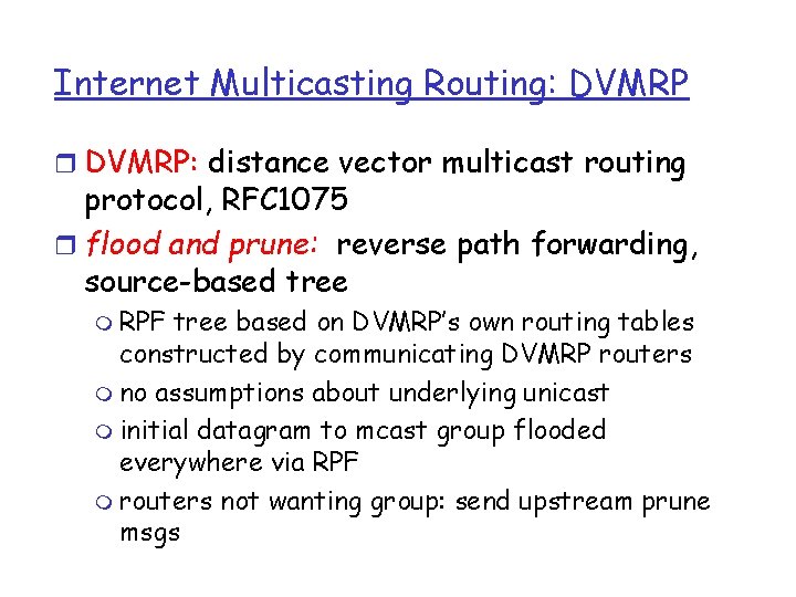
Internet Multicasting Routing: DVMRP r DVMRP: distance vector multicast routing protocol, RFC 1075 r flood and prune: reverse path forwarding, source-based tree m RPF tree based on DVMRP’s own routing tables constructed by communicating DVMRP routers m no assumptions about underlying unicast m initial datagram to mcast group flooded everywhere via RPF m routers not wanting group: send upstream prune msgs

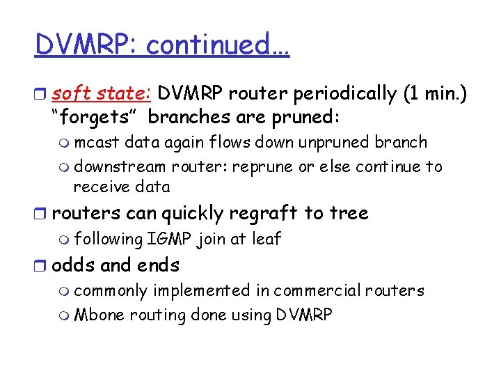
DVMRP: continued… r soft state: DVMRP router periodically (1 min. ) “forgets” branches are pruned: m mcast data again flows down unpruned branch m downstream router: reprune or else continue to receive data r routers can quickly regraft to tree m following IGMP join at leaf r odds and ends m commonly implemented in commercial routers m Mbone routing done using DVMRP

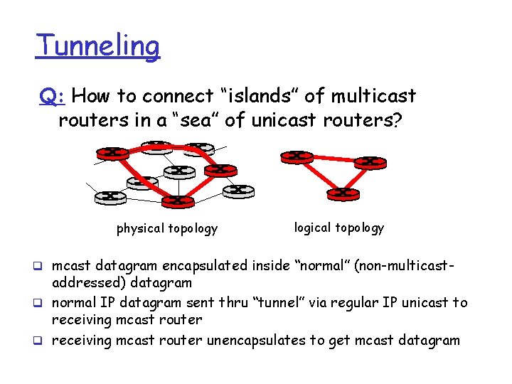
Tunneling Q: How to connect “islands” of multicast routers in a “sea” of unicast routers? physical topology logical topology q mcast datagram encapsulated inside “normal” (non-multicast- addressed) datagram q normal IP datagram sent thru “tunnel” via regular IP unicast to receiving mcast router q receiving mcast router unencapsulates to get mcast datagram

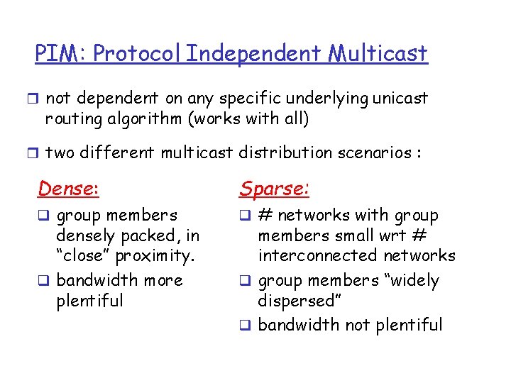
PIM: Protocol Independent Multicast r not dependent on any specific underlying unicast routing algorithm (works with all) r two different multicast distribution scenarios : Dense: Sparse: q group members q # networks with group densely packed, in “close” proximity. q bandwidth more plentiful members small wrt # interconnected networks q group members “widely dispersed” q bandwidth not plentiful

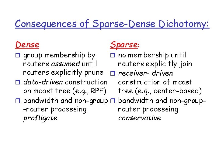
Consequences of Sparse-Dense Dichotomy: Dense r group membership by Sparse: r no membership until routers assumed until routers explicitly prune r r data-driven construction on mcast tree (e. g. , RPF) r bandwidth and non-group r -router processing profligate routers explicitly join receiver- driven construction of mcast tree (e. g. , center-based) bandwidth and non-grouprouter processing conservative

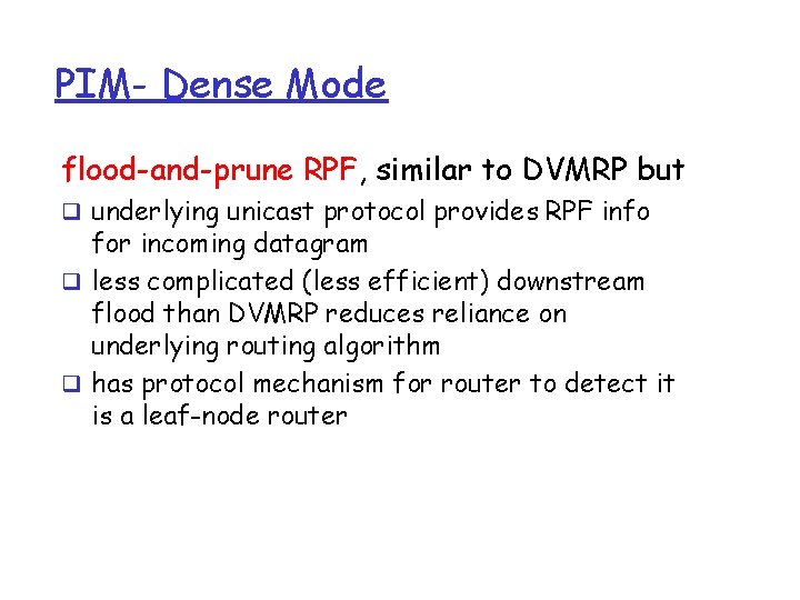
PIM- Dense Mode flood-and-prune RPF, similar to DVMRP but q underlying unicast protocol provides RPF info for incoming datagram q less complicated (less efficient) downstream flood than DVMRP reduces reliance on underlying routing algorithm q has protocol mechanism for router to detect it is a leaf-node router

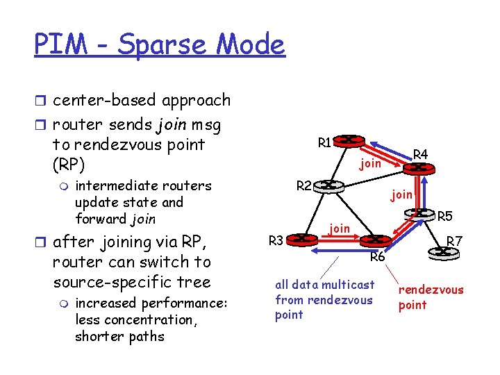
PIM - Sparse Mode r center-based approach r router sends join msg to rendezvous point (RP) m router can switch to source-specific tree increased performance: less concentration, shorter paths R 4 join intermediate routers update state and forward join r after joining via RP, m R 1 R 2 R 3 join R 5 join R 6 all data multicast from rendezvous point R 7 rendezvous point

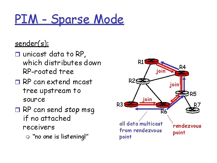
PIM - Sparse Mode sender(s): r unicast data to RP, which distributes down RP-rooted tree r RP can extend mcast tree upstream to source r RP can send stop msg if no attached receivers m “no one is listening!” R 1 R 4 join R 2 R 3 join R 5 join R 6 all data multicast from rendezvous point R 7 rendezvous point

Chapter 4: summary r 4. 1 Introduction r 4. 2 Virtual circuit and datagram networks r 4. 3 What’s inside a router r 4. 4 IP: Internet Protocol m m Datagram format IPv 4 addressing ICMP IPv 6 r 4. 5 Routing algorithms m Link state m Distance Vector m Hierarchical routing r 4. 6 Routing in the Internet m m m RIP OSPF BGP r 4. 7 Broadcast and multicast routing Hálózati réteg 146
 Rteg
Rteg Rteg
Rteg Rteg
Rteg Loan x has a principal of $10 000x
 Difference between note making and note taking
 Draw a specimen of debit note
 Examples of signal words
 What is debit note and credit note
 Difference between note making and note taking
 Note taking definition
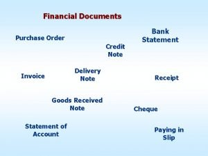
 Financial documents in order
 Sự nuôi và dạy con của hươu
 điện thế nghỉ
 Nguyên nhân của sự mỏi cơ sinh 8
 Một số thể thơ truyền thống
 Trời xanh đây là của chúng ta thể thơ
 Voi kéo gỗ như thế nào
 Thiếu nhi thế giới liên hoan
 Số nguyên là gì
 Tỉ lệ cơ thể trẻ em
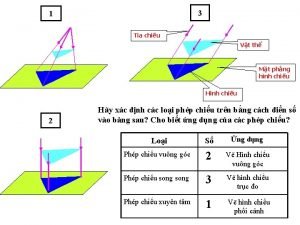
 Vẽ hình chiếu vuông góc của vật thể sau
 Các châu lục và đại dương trên thế giới
 Thế nào là hệ số cao nhất
 Sơ đồ cơ thể người
 Tư thế ngồi viết
 Hát kết hợp bộ gõ cơ thể
 đặc điểm cơ thể của người tối cổ
 Mật thư tọa độ 5x5
 Glasgow thang điểm
 ưu thế lai là gì
 Tư thế ngồi viết
 Thẻ vin
 Thể thơ truyền thống
 Bàn tay mà dây bẩn
 Các châu lục và đại dương trên thế giới
 Từ ngữ thể hiện lòng nhân hậu
 Diễn thế sinh thái là
 Ng-html
 V. c c
 Làm thế nào để 102-1=99
 Chúa yêu trần thế
 Hổ đẻ mỗi lứa mấy con
 đại từ thay thế
 Vẽ hình chiếu vuông góc của vật thể sau
 Quá trình desamine hóa có thể tạo ra
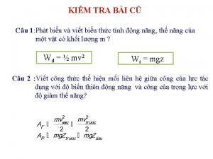
 Công của trọng lực
 Thế nào là mạng điện lắp đặt kiểu nổi
 Lời thề hippocrates
 Các loại đột biến cấu trúc nhiễm sắc thể
 Bổ thể
 Vẽ hình chiếu đứng bằng cạnh của vật thể
 Phản ứng thế ankan
 Các môn thể thao bắt đầu bằng tiếng nhảy
 Why did the author use numbers and stats
 Note taking process
 India short note
 Matrice de specificatii limba romana
 Flow method note taking
 Parts of essay introduction
 Notice and note close reading
 Note receivable debit or credit
 Did you get the note?
 Functions of industrial estate
 Cold chain short note
 Prise de note
 Hospital management system
 Natajukope
 Birp note example
 What are the five r's of note taking
 A note is generally defined as:
 Cliff baxter note
 Comlex question bank
 Romanit suomessa
 Post it note
 Jedan kruh na svetom stolu note
 Short note on regulation of blood pressure
 Note de cadrage tms pro
 Synthèse exemple
 Osteoarthritis soap note
 Note card system
 Bibliography card example
 Sred te se pećine
 How to use has and have
 Soap note nutrition
 How to write a casenote
 In a statistical table prefatory note is shown
 Extreme or absolute language
 Jedan kruh na svetom stolu
 Velika nam djela učini gospodin opet smo radosni note
 Progress notes examples
 Dar note example
 Slusao sam jedno jutro
 Ankle sprain soap note
 Cornell note taking strategy
 Mahatma gandhi short note
 App note
 Prerequisites of note-taking
 Powder keg of europe ww1
 Write a detailed note on unicast routing protocols
 Examples of friendly letters
 Micrososft one note
 Thank you note to preceptor after orientation
 Note tak gdprintprecalc ap answers
 Ob/gyn progress note template
 Five r's of note taking
 Death pronouncement note example
 Modular inverse
 Cards evaluation of sources
 Crime scene note taking
 Ot soap note example
 Attending attestation
 Characteristics of promissory note
 Concept proposal
 Visual communication drawing
 On a more important note
 Animal behavior worksheet
 Skladba v počasnem tempu
 Paraphrase note card example
 Recorder karate belt colors
 Simple interest formula
 Stop notice and note
 Vostok ice core data
 On an unrelated note
 Velika nam djela učini gospodin opet smo radosni note
 Documentary note referencing style
 Role of industrial estate in entrepreneurship development
 Alcohol to alkyl halide
 Apa authors note
 Note payble
 Note divertenti
 Non performing note
 Life above zero
 How to write note making
 1941-1882
 Aha moment signpost
 Pc notes taker
 Thank you note to facilitator
 Note on islam
 Signposts notice and note
 Description of the vowel sounds
 Note cards mla format
 Notes receivable
 Newborn letter to mom
 Two effects of allied bombing raids on japan
 According to walter pauk, 10 weeks after lecture
 Histo and geo note
 Thank you facilitator


