Amateur Extra License Class Chapter 4 Electrical Principles


 = a/c or θ = Arc.")


")

 Example")


 where: X")
 where: X")


 Formerly")


 P = I x E")


 Quality factor (Q) of a resonant ckt is a measure of")
 • Internal series resistance of an inductor is almost always greater")
 Quality factor (Q) of a resonant ckt is a measure of")
 Note: During our class I was not satisfied with the explanation")
 » BW = f 2 -f")


- Slides: 163
Amateur Extra License Class Chapter 4 Electrical Principles
Chapter 4 Electrical Principles • Electric & Magnetic Fields • RC & RL Time Constants • Phase Angle • Radio Mathematics • Complex Impedance • Plotting Impedance • Admittance • Real Power & Power Factor • Resonant Circuits • Q Factor & Band Width • @ Radio & Microwave Freqs • Magnetic Cores
Electric and Magnetic Fields • Field » Region of space where energy is stored and through which a force acts o Energy stored in a field is called potential energy » Fields are undetectable by any of the 5 human senses o o You can only observe the effects of a field Example: Gravity
Electric and Magnetic Fields Electric Field Magnetic Field • Detected by a voltage difference between 2 points • Every electrical charge has an electric field • Electrical energy is stored by moving electrical charges apart so that there is a voltage difference (or potential) between them • Detected by effect on moving electrical charges (current) • An electrical current has an associated magnetic field • Magnetic energy is stored by moving electrical charges to create an electrical current » Voltage potential = potential energy • An electrostatic field is an electric field that does not change over time • A magnetostatic field is a magnetic field that does not change over time » Stationary permanent magnet » Earth’s magnetic field
Electric and Magnetic Fields Magnetic Field Direction
Electric and Magnetic Fields Electromagnetic Waves https: //www. khanacademy. org/science/physics/light-waves
Electric and Magnetic Fields Electromagnetic Waves W L e v a e (λ h t ng )
Electric and Magnetic Fields Electromagnetic Waves Direction of Propagation
Electric and Magnetic Fields Electromagnetic Waves
Electric and Magnetic Fields Electromagnetic Waves
E 3 A 15 – What is an electromagnetic wave? A. A wave of alternating current in the core of an electromagnet B. A wave consisting of two electric fields at parallel right angles to each other C. A wave consisting of an electric field and a magnetic field oscillating at right angles to each other D. A wave consisting of two magnetic fields at right angles to each other
E 3 A 16 – Which of the following best describes electromagnetic waves travelling in free space? A. Electric and magnetic fields become aligned as they travel B. The energy propagates through a medium with high refractive index C. The waves are reflected by the ionosphere and return to their source D. Changing electric and magnetic fields propagate the energy
E 3 A 17 – What is meant by circularly polarized electromagnetic waves? A. Waves with an electric field bent into a circular shape B. Waves with a rotating electric field C. Waves that circle the Earth D. Waves produced by a loop antenna
E 5 D 06 -- In what direction is the magnetic field oriented about a conductor in relation to the direction of electron flow? A. In the same direction as the current B. In a direction opposite to the current C. In all directions; omnidirectional D. In a direction determined by the left-hand rule
E 5 D 07 -- What determines the strength of a magnetic field around a conductor? A. The resistance divided by the current B. The ratio of the current to the resistance C. The diameter of the conductor D. The amount of current flowing through a conductor
E 5 D 08 -- What type of energy is stored in an electromagnetic or electrostatic field? A. Electromechanical energy B. Potential energy C. Thermodynamic energy D. Kinetic energy
RC and RL Time Constants R-C Circuit R-L Circuit
RC and RL Time Constants Voltage Charging Across Capacitor in RC Ckt Voltage Discharging Across Capacitor in RC Ckt
Current Increasing Across Inductor in RL Ckt % Current Across Inductor INCREASE % Current Across Inductor RC and RL Time Constants Current Decreasing Across Inductor in RL Ckt DECREASE
RC and RL Time Constants 100% % Voltage Across Capacitor or % Current Across Inductor 90% 80% 70% Charging V for RC Increasing I for RL 60% 50% 40% 30% 20% 10% Discharging V for RC Decreasing I for RL
RC and RL Time Constants R-C circuit R-L Circuit In an R-C circuit, one time constant is defined as the length of time it takes the voltage across an uncharged capacitor to reach 63. 2% of its final value. In an R-L circuit, one time constant is defined as the length of time it takes the current through an inductor to reach 63. 2% of its final value. Time Constant in seconds, τ=Rx. C τ = L/R
RC and RL Time Constants Charging Discharging Time Constants Percentage of Applied Voltage Percentage of Starting Voltage 1 63. 20% 36. 80% 2 86. 50% 13. 50% 3 95. 00% 4 98. 20% 1. 80% 5 99. 30% 0. 70% Note: After a period of 5 time constants, the voltage or current can be assumed to have reached its final value. “Close enough for all practical purposes. ”
RC and RL Time Constants 100% % Voltage Across Capacitor or % Current Across Inductor 90% 80% 70% Charging V for RC Increasing I for RL 60% 50% 40% 30% 20% 10% Discharging V for RC Decreasing I for RL
E 5 B 01 -- What is the term for the time required for the capacitor in an RC circuit to be charged to 63. 2% of the applied voltage? A. An exponential rate of one B. One time constant C. One exponential period D. A time factor of one Charging Discharging Time Constants Percentage of Applied Voltage Percentage of Starting Voltage 1 2 3 4 5 63. 20% 86. 50% 95. 00% 98. 20% 99. 30% 36. 80% 13. 50% 5. 00% 1. 80% 0. 70%
E 5 B 02 -- What is the term for the time it takes for a charged capacitor in an RC circuit to discharge to 36. 8% of its initial voltage? A. One discharge period B. An exponential discharge rate of one C. A discharge factor of one D. One time constant Charging Discharging Time Constants Percentage of Applied Voltage Percentage of Starting Voltage 1 2 3 4 5 63. 20% 86. 50% 95. 00% 98. 20% 99. 30% 36. 80% 13. 50% 5. 00% 1. 80% 0. 70%
E 5 B 04 -- What is the time constant of a circuit having two 220 -microfarad capacitors and two 1 -megohm resistors, all in parallel? A. 55 seconds B. 110 seconds C. 440 seconds D. 220 seconds
E 5 B 04 -- What is the time constant of a circuit having two 220 -microfarad capacitors and two 1 -megohm resistors, all in parallel? R 1 = R 2 = 1 x 10⁶ Ω C 1 = C 2 = 220 x 10 -6 F
Phase Angle Difference in Time Between 2 Signals • At the same frequency • Measured in degrees θ = 45º
Phase Angle t Lagging signal is behind 2 nd signal. Blue signal lags red signal. Amplitude Leading signal is ahead of 2 nd signal. Blue signal leads red signal. t
Phase Angle or Current leads the voltage by 90° or Current lags the voltage by 90° t Amplitude AC Voltage-Current Relationship in Inductors Voltage leads the current by 90° Amplitude AC Voltage-Current Relationship in Capacitors Voltage lags the current by 90° Blue = Voltage Red = Current t
Phase Angle Combining Reactance With Resistance • In a resistor, the voltage and the current are always in phase. • In a circuit with both resistance and capacitance, the voltage will lag current by less than 90°. • In a circuit with both resistance and inductance, the voltage will lead current by less than 90°. • The size of the phase angle depends on the relative sizes of the resistance to the inductance or capacitance.
Phase Angle • “Lead” or “Lag” “In-phase” or “Out-of-phase” Shows the Relationship of One Waveform to Another • Difficult to Visualize Angular or Phasor Difference Between Two or More Waveforms • Use Phasor Diagrams with Rotating Vectors
Phase Angle Phasor Diagrams with Rotating Vectors
E 5 B 09 -- What is the relationship between the current through a capacitor and the voltage across a capacitor? A. Voltage and current are in phase B. Voltage and current are 180 degrees out of phase C. Voltage leads current by 90 degrees D. Current leads voltage by 90 degrees
E 5 B 10 -- What is the relationship between the current through an inductor and the voltage across an inductor? A. Voltage leads current by 90 degrees B. Current leads voltage by 90 degrees C. Voltage and current are 180 degrees out of phase D. Voltage and current are in phase
E 5 C 05 – What is the name of the diagram used to show the phase relationship between impedances at a given frequency? A. Venn diagram B. Near field diagram C. Phasor diagram D. Far field diagram
Radio Mathematics Basic Trigonometry c • Sine sin(θ) = a/c or θ = Arc. Sin(a/c) • Cosine cos(θ) = b/c or θ = Arc. Cos(b/c) • Tangent tan(θ) = a/b or θ = Arc. Tan(a/b) θ b a
Radio Mathematics • Coordinate Systems » Complex impedances can be plotted using a 2 -dimensional coordinate system » There are two primary types of coordinate systems used for plotting impedances: 1. Rectangular 2. Polar
Radio Mathematics Rectangular Coordinates • Also called Cartesian coordinates • A pair of numbers specifies a position on the graph: (x, y) • 1 st number (x) specifies position along horizontal axis • 2 nd number (y) specifies position along vertical axis Example A in Rectangular Coordinates 2 Example B in Rectangular Coordinates 3 -4 2
Radio Mathematics Polar Coordinates • A pair of numbers specifies a position on the graph: (r, θ) • r specifies distance from the origin • θ specifies angle from horizontal axis • Polar Coordinates used to specify a vector Vector: Line with BOTH length & direction. Represented by a 90º single-headed arrow 4/30º • Length of vector is impedance • Angle of vector is phase angle • Angle always between +90⁰ and -90⁰ 30º -45º 0º 5/-45º -90º
Radio Mathematics Working with Rectangular & Polar Coordinates Converting Rectangular to Polar (x, y) convert to r /θ r = x 2 +y 2 θ = Arc. Tan (y/x) In “radio-speak”, you will see this notation Converting Polar to Rectangular r /θ convert to (x, y) x = r * cos(θ) y = r * sin(θ) In “radio-speak”, you will see this notation
Radio Mathematics Example A in Rectangular Coordinates 2 Example B in Rectangular Coordinates 2 3 -4 Example A in Polar Coordinates 3. 6 /33. 7º Example B in Polar Coordinates 4. 5 /-63. 4º
Radio Mathematics r = x 2 + y 2 θ = Arc. Tan(y/x) Example A: r = x 2 + y 2 = 32 + 22 = 9 + 4 = 13 = 3. 6 θ = Arc. Tan(y/x) = Arc. Tan(2/3) = 33. 7° Example B: r = x 2 + y 2 = 22 + -42 = 2 + 16 = 20 = 4. 5 θ = Arc. Tan(y/x) = Arc. Tan(-4/2) = -63. 4° r y θ x
Radio Mathematics Complex Numbers Also called “imaginary”numbers Represented by x + jy where j = “x” is the “real” part “jy” is the “imaginary” part In “radio-speak”, you will see this notation
Radio Mathematics • Complex Numbers can be expressed in either rectangular or polar coordinates » Adding/subtracting complex numbers more easily done using rectangular coordinates (a + jb) + (c + jd) = (a+c) + j(b+d) (a + jb) - (c + jd) = (a-c) + j(b-d) » Multiplying/dividing complex numbers more easily done using polar coordinates a/θ 1 x b/θ 2 = a x b /θ 1 + θ 2 a/θ 1 / b/θ 2 = a / b /θ 1 - θ 2
E 5 C 07 – What is a vector? A. The value of a quantity that changes over time B. A quantity with both magnitude and an angular component C. The inverse of the tangent function D. The inverse of the sine function
E 5 C 11 -- What do the two numbers that are used to define a point on a graph using rectangular coordinates represent? A. The magnitude and phase of the point B. The sine and cosine values C. The coordinate values along the horizontal and vertical axes D. The tangent and cotangent values
Complex Impedance Capacitive Reactance • Reactance decreases with increasing frequency. • Capacitor looks like open circuit at 0 Hz (DC). • Capacitor looks like short circuit at very high frequencies. Inductive Reactance • Reactance increases with increasing frequency. • Inductor looks like short circuit at 0 Hz (DC). • Inductor looks like open circuit at very high frequencies.
Complex Impedance When resistance is combined with reactance the result is called impedance, Z Rectangular Coordinates Polar Coordinates (Where X = XL – XC)
Plotting Impedance
Plotting Impedance |Z|= R 2 + X 2 θ = Arc. Tan(X/R) where: X = XL - XC = 600 -0 = 600 Ω |Z| = R 2 + X 2 = 6002 + 6002 = 360000 + 360000 = 720000 = 848. 5Ω θ = Arc. Tan(X/R) = Arc. Tan(600/600) = Arc. Tan(1) = 45° Z = 848. 5 Ω /45° R = 600Ω Z= 8. 5 4 8 Ω Θ = 45º X = j 600Ω Plot R=600 Ω and XL= 600 Ω Show total Impedance & Phase Angle
Plotting Impedance |Z|= R 2 + X 2 θ = Arc. Tan(X/R) where: X = XL - XC = 0 -600 = -600 Ω |Z| = R 2 + X 2 = 6002 + -6002 = 360000 + 360000 = 720000 = 848. 5Ω θ = Arc. Tan(X/R) = Arc. Tan(-600/600) = Arc. Tan(-1) = -45° Z = 848. 5 Ω /-45° Z= Θ = -45º 84 8. 5 Ω R = 600Ω X = -j 600Ω Plot R=600 Ω and XC= 600 Ω Show total Impedance & Phase Angle
Plotting Impedance Z = 848. 5 Ω /-45° Z= Θ = -45º 84 8. 5 Ω R = 600Ω XC = -j 1200Ω X = -j 600Ω |Z|= R 2 + X 2 θ = Arc. Tan(X/R) where: X = XL - XC = 600 -1200 = -600 Ω |Z| = R 2 + X 2 = 6002 + -6002 = 360000 + 360000 = 720000 = 848. 5Ω θ = Arc. Tan(X/R) = Arc. Tan(-600/600) = Arc. Tan(-1) = -45° XL = j 600Ω Plot R=600 Ω, XL= 600 Ω & XC= 1200 Ω Show total Impedance & Phase Angle
Plotting Impedance X Case 1: If R = X, then = ± 45° Z = ± 45° R Case 2: X If R > X, then < ± 45° Z < ± 45° R X Case 3: If R < X, then > ± 45° Z > ± 45° R Phase Angle is Positive if Reactance is Inductive Phase Ange is Negative if Reactance is Capacitive
E 5 B 07 -- What is the phase angle between the voltage across and the current through a series RLC circuit if XC is 500 ohms, R is 1 kilohm, and XL is 250 ohms? A. B. C. D. 68. 2 degrees with the voltage leading the current 14. 0 degrees with the voltage lagging the current 68. 2 degrees with the voltage lagging the current Circuit is capacitive since capacitive reactance is larger than the inductive reactance. AC voltage-current relationship in capacitive circuits is voltage lagging current (negative phase angle), eliminating Choices A and B. Between choices C and D, Choice D has a phase angle greater than 45° indicating the Reactance is larger than the Resistance. Choice C has a phase angle less than 45° indicating a larger Resistance value than Reactance. In this problem, the Resistance is larger than the resultant reactance so the phase angle is expected to be less than 45°. Choice C is the correct answer.
E 5 B 07 -- What is the phase angle between the voltage across and the current through a series RLC circuit if XC is 500 ohms, R is 1 kilohm, and XL is 250 ohms? θ = Arc. Tan(X/R) where: X = XL - XC = 250 - 500 = -250 Ω θ = Arc. Tan(X/R) = Arc. Tan(-250/1000) = Arc. Tan(-0. 25) = -14. 04° The phase angle is negative making this circuit capacitive. AC voltage-current relationship in capacitive circuits is voltage lagging current. Note that voltage is the reference point for phase angle polarity, so with a negative phase angle, voltage lags current.
E 5 C 01 – Which of the following represents a capacitive reactance in rectangular notation? A. -j. X B. +j. X C. X D. Omega
E 5 C 02 – How are the impedances described in polar coordinates? A. By X and R values B. By real and imaginary parts C. By phase angle and amplitude D. By Y and G values
E 5 C 03 – Which of the following represents an inductive reactance in polar coordinates? A. A positive real part B. A negative real part C. A positive phase angle D. A negative phase angle
E 5 C 04 – Which of the following represents a capacitive reactance in polar coordinates? A. A positive real part B. A negative real part C. A positive phase angle D. A negative phase angle
E 5 C 06 – What does the impedance 50 – j 25 represent? A. 50 ohms resistance in series with 25 ohms inductive reactance B. 50 ohms resistance in series with 25 ohms capacitive reactance C. 25 ohms resistance in series with 50 ohms inductive reactance D. 25 ohms resistance in series with 50 ohms capacitive reactance
E 5 C 08 – What coordinate system is often used to display the phase angle of a circuit containing resistance, inductive and/or capacitive reactance? A. Maidenhead grid B. Faraday grid C. Elliptical coordinates D. Polar coordinates
E 5 C 09 -- When using rectangular coordinates to graph the impedance of a circuit, what does the horizontal axis represent? A. Resistive component B. Reactive component C. The sum of the reactive and resistive components D. The difference between the resistive and reactive components
E 5 C 10 -- When using rectangular coordinates to graph the impedance of a circuit, what does the vertical axis represent? A. Resistive component B. Reactive component C. The sum of the reactive and resistive components D. The difference between the resistive and reactive components
E 5 C 12 -- If you plot the impedance of a circuit using the rectangular coordinate system and find the impedance point falls on the right side of the graph on the horizontal axis, what do you know about the circuit? A. It has to be a direct current circuit B. It contains resistance and capacitive reactance C. It contains resistance and inductive reactance D. It is equivalent to a pure resistance
E 5 C 13 -- What coordinate system is often used to display the resistive, inductive, and/or capacitive reactance components of an impedance? A. Maidenhead grid B. Faraday grid C. Elliptical coordinates D. Rectangular coordinates
E 5 C 14 -- Which point on Figure E 5 -2 best represents that impedance of a series circuit consisting of a 400 ohm resistor and a 38 picofarad capacitor at 14 MHz? A. Point 2 B. Point 4 C. Point 5 D. Point 6 The circuit has no inductance, eliminating all points in the upper right quadrant. Choices A and D are eliminated. The left side of the impedance plot is never used, eliminating Choice C. Leaving B as the correct choice.
E 5 C 17 -- Which point on Figure E 5 -2 best represents the impedance of a series circuit consisting of a 300 ohm resistor, a 0. 64 -microhenry inductor and an 85 picofarad capacitor at 24. 900 MHz? A. Point 1 B. Point 3 C. Point 5 D. Point 8 The left side of the impedance plot is never used, eliminating Choice C. XL = 2πf. L = 2 x 3. 14 x 24. 9 x 106 x 0. 64 x 10 -6 = 100. 13Ω XC = 1/2πf. C = 1/2 x 3. 14 x 24. 9 x 106 x 85 x 10 -12 = 75. 2Ω X = XL - XC = 100. 13 – 75. 2 = 25Ω Choices A & B can be eliminated because Points 1 & 3 represents reactance values of ± 400Ω. Leaving D, Point 8 as the correct choice.
Tips for Calculating Impedance • In Series Circuits, Add Impedances » Inductive & Capacitive Reactance in Series Cancel • In Parallel Circuits, Add Admittances
Admittance , Y = 1/Z = G + j B Where Conductance, G = 1/R and Susceptance, B = 1/X |Y| = G 2 + B 2 / Y = Arc. Tan(B/G) = Arc. Tan (-X/R) Note: When taking the reciprocal of an angle, the sign changes from positive to negative or vice versa.
Admittance • Unit of measure for Y, G, & B is Siemens (S) Formerly “mho” • Example: An impedance of 141Ω @ /45° is equivalent to an admittance of 7. 09 millisiemens @ /-45° |Y| = 1/|Z| = 1/141 = 0. 00709 = 7. 09 x 10 -3 / Y = 1// Z = 1//45° = /-45°
Admittance Calculate impedance of parallel R-L circuit. Since components are in parallel, Use Admittance XL 400Ω • Y = G + j. B, where G = 1/R and B = 1/X • |Y| = G 2 + B 2 / Y = Arc. Tan(B/G) Then convert to Impedance • |Z| = 1/Y / Z = Arc. Tan(-B/G) 300Ω
Admittance Calculate impedance of parallel R-L Ckt G = 1/R = 1/300 = 0. 0033 S XL B = 1/X = 1/j 400 = (1/j)(1/400) = -j 0. 0025 S 400Ω Y = G + j. B = 0. 00333 – j 0. 0025 S |Y| = G 2 + B 2 = (0. 0033)2 + (-0. 0025)2 = 11. 1 x 10 -6 + 6. 25 X 10 -6 = 17. 4 x 10 -6 = 0. 00417 S / Y = Arc. Tan(B/G) = Arc. Tan(-0. 00250/0. 00333) = Arc. Tan(-0. 75) = -36. 9° Z = 1/Y = 1/0. 00417 = 240 Ω /36. 9° 300Ω
E 5 B 03 – What happens to the phase angle of a reactance when it is converted to a susceptance? A. It is unchanged B. The sign is reversed C. It is shifted by 90% D. The susceptance phase angle is the inverse of the reactance phase angle
E 5 B 05 – What happens to the magnitude of a reactance when it is converted to a susceptance? A. It is unchanged B. The sign is reversed C. It is shifted by 90 degrees D. The magnitude of the susceptance is the reciprocal of the magnitude of the reactance
E 5 B 06 – What is susceptance? A. The magnetic impedance of a circuit B. The ratio of magnetic field to electric field C. The inverse of reactance D. A measure of the efficiency of a transformer
E 5 B 12 – What is admittance? A. The inverse of impedance B. The term for the gain of a field effect transistor C. The turns ratio of a transformer D. The unit used for Q factor
E 5 B 13 – What letter is commonly used to represent susceptance? A. G B. X C. Y D. B
Electrical Principles • Power » Rate at which energy is transferred » Rate of doing work (using energy) over time » Unit for electrical power is the watt » 1 watt = 1 joule/second » The production of one joule per second is one watt
Real Power & Power Factor Resistive Power Reactive Power Resistance consumes energy Capacitance & inductance only store & return energy, they do not consume it • Voltage & current are in phase (θ = 0°) • Work is done • Power is used • Voltage & current are 90° out of phase (θ = 90°) • No work is done • No power is used
Real Power & Power Factor • Apparent Power (v-a) P = I x E » Only works when voltage & current are in phase • Real or True Power (watts) P = I x E x cos(θ) • Power Factor (PF) = cos(θ) = (Real Pwr) / (Apparent Pwr) » Always less than or equal to 1
Real Power & Power Factor Voltage & Current In Phase Θ = Zero, Pure Resistive Voltage & Current Out of Phase Θ > Zero, Reactance > Zero
E 5 D 09 -- What happens to reactive power in an AC circuit that has both ideal inductors and ideal capacitors? A. It is dissipated as heat in the circuit B. It is repeatedly exchanged between the associated magnetic and electric fields, but is not dissipated C. It is dissipated as kinetic energy in the circuit D. It is dissipated in the formation of inductive and capacitive fields
E 5 D 10 -- How can the true power be determined in an AC circuit where the voltage and current are out of phase? A. By multiplying the apparent power times the power factor B. By dividing the reactive power by the power factor C. By dividing the apparent power by the power factor D. By multiplying the reactive power times the power factor
E 5 D 11 -- What is the power factor of an R-L circuit having a 60 degree phase angle between the voltage and the current? A. 1. 414 B. 0. 866 C. 0. 5 D. 1. 73 Power Factor (PF) = cos(θ) = cos(60°) = 0. 5 Eliminate answers A & D because a power factors are never greater than 1.
E 5 D 12 -- How many watts are consumed in a circuit having a power factor of 0. 2 if the input is 100 -V AC at 4 amperes? A. 400 watts B. 80 watts P = I x E x cos(θ) = 4 x 100 x. 2 = 80 watts C. 2000 watts D. 50 watts
E 5 D 13 -- How much power is consumed in a circuit consisting of a 100 ohm resistor in series with a 100 ohm inductive reactance drawing 1 ampere? A. 70. 7 Watts B. 100 Watts C. 141. 4 Watts D. 200 Watts P = I 2 x R = 12 x 100 = 1 X 100 = 100 watts
E 5 D 14 -- What is reactive power? A. Wattless, nonproductive power B. Power consumed in wire resistance in an inductor C. Power lost because of capacitor leakage D. Power consumed in circuit Q
Resonance • Mechanical systems have a natural frequency where they want to oscillate when stimulated. • This is called resonance. • Electrical circuits containing both capacitors and inductors behave in a similar manner.
Resonant Circuits • As frequency increases, inductive reactance increases. • As frequency increases, capacitive reactance decreases. • At resonant frequency, inductive reactance & capacitive reactance are equal, XL = XC
Resonant Circuits • At the resonant frequency » XL = X C » Inductive & capacitive reactance cancel out » Circuit impedance is purely resistive » Voltage & current are in phase
Series Resonant Circuit • • Impedance is at the minimum Current is maximum At resonance, Z = RS Sum of individual voltages greater than applied voltage Voltage across resistor equal to applied voltage Series L-C circuit impedance = 0 Ω (short ckt) Inductive above resonant frequency Capacitive below resonant frequency
Parallel Resonant Circuit • • Impedance is at the maximum Current is minimum At resonance, Z = RP Sum of currents through all components greater than current through ckt Current through resistor equals current through ckt Parallel L-C circuit impedance = ∞ Ω (open ckt) Capacitive above resonant frequency Inductive below resonant frequency
E 5 A 01 -- What can cause the voltage across reactances in series to be larger than the voltage applied to them? A. Resonance B. Capacitance C. Conductance D. Resistance
E 5 A 02 -- What is resonance in an electrical circuit? A. The highest frequency that will pass current B. The lowest frequency that will pass current C. The frequency at which the capacitive reactance equals the inductive reactance D. The frequency at which the reactive impedance equals the resistive impedance
E 5 A 03 -- What is the magnitude of the impedance of a series RLC circuit at resonance? A. High, as compared to the circuit resistance B. Approximately equal to capacitive reactance C. Approximately equal to inductive reactance D. Approximately equal to circuit resistance
E 5 A 04 -- What is the magnitude of the impedance of a circuit with a resistor, an inductor and a capacitor all in parallel, at resonance? A. Approximately equal to circuit resistance B. Approximately equal to inductive reactance C. Low, as compared to the circuit resistance D. Approximately equal to capacitive reactance
E 5 A 05 -- What is the magnitude of the current at the input of a series RLC circuit as the frequency goes through resonance? A. Minimum B. Maximum C. R/L D. L/R
E 5 A 06 -- What is the magnitude of the circulating current within the components of a parallel LC circuit at resonance? A. It is at a minimum B. It is at a maximum C. It equals 1 divided by the quantity 2 times Pi, multiplied by the square root of inductance L multiplied by capacitance C D. It equals 2 multiplied by Pi, multiplied by frequency, multiplied by inductance
E 5 A 07 -- What is the magnitude of the current at the input of a parallel RLC circuit at resonance? A. Minimum B. Maximum C. R/L D. L/R
E 5 A 08 -- What is the phase relationship between the current through and the voltage across a series resonant circuit at resonance? A. The voltage leads the current by 90 degrees B. The current leads the voltage by 90 degrees C. The voltage and current are in phase D. The voltage and current are 180 degrees out of phase
E 5 A 14 -- What is the resonant frequency of a series RLC circuit if R is 22 ohms, L is 50 microhenrys and C is 40 picofarads? A. 44. 72 MHz B. 22. 36 MHz C. 3. 56 MHz D. 1. 78 MHz f. R = 1 / (2π LC ) = 1 / (2 x 3. 14 x 50 x 10 -6 x 40 x 10 -12) = 1 / (2 x 3. 14 x 2 x 10 -15) = 1 / (2 x 3. 14 x 4. 47 x 10 -8) = 1/ 2. 81 x 10 -7 = 3. 56 MHz
Quality Factor (Q) Quality factor (Q) of a resonant ckt is a measure of the “goodness” For Series Resonant Circuits: Q = Pstored/Pdissipated = I 2 X / I 2 R Q = X/R Where: X = Capacitive or Inductive reactance at resonance R = Series resistance
Quality Factor (Q) • Internal series resistance of an inductor is almost always greater than internal series resistance of a capacitor » Resistance of inductor is primarily responsible for Q of circuit • Q = X / R ≈ XL / R = 2∏f. L / R • Q always goes down when resistance is added in series with a component • Increasing frequency increases Q
Quality Factor (Q) Quality factor (Q) of a resonant ckt is a measure of the “goodness” For Parallel Resonant Circuits, where a large value of R is in parallel with C and L Q = R/X Where: X = Capacitive or Inductive reactance at resonance R = Resistance Note: Q = X/R for a small R in series with L. This is the case in practical applications, as we are mostly concerned with the internal resistance of the inductor limiting the Q.
Quality Factor (Q) Note: During our class I was not satisfied with the explanation I gave for the note at the bottom of the previous slide. Better explanation provided below. Q = Pstored/Pdissipated = I 2 X / I 2 R Q=X/R where: X = Capacitive or Inductive reactance at resonance R = Series resistance This formula is applicable to series resonant circuits, and also parallel resonant circuits if the resistance is in series with the inductor. This is the case in practical applications, as we are mostly concerned with the resistance of the inductor limiting the Q. Some text show Q = R / X for a parallel resonant circuit. This is correct for a large value of R in parallel with L and C. Q = X / R is correct for a small R in series with L
Bandwidth of Resonant Circuits • Half-power bandwidth (BW) » BW = f 2 -f 1 Frequency difference between -3 d. B points » BW = f 2 -f 1 = Δf = f 0 / Q = f. R / Q
Bandwidth of Resonant Circuits • Q affects bandwidth & efficiency of circuit » Higher Q Higher efficiency (lower losses) » Higher Q Narrower bandwidth
E 4 B 15 -- Which of the following can be used as a relative measurement of the Q for a seriestuned circuit? A. The inductance to capacitance ratio B. The frequency shift C. The bandwidth of the circuit's frequency response D. The resonant frequency of the circuit
E 5 A 09 – How is the Q of an RLC parallel resonant circuit calculated? A. Reactance of either the inductance or capacitance divided by the resistance B. Reactance of either the inductance or capacitance multiplied by the resistance C. Resistance divided by the reactance of either the inductance or capacitance D. Reactance of the inductance multiplied by the reactance of the capacitance
E 5 A 10 – How is the Q of an RLC series resonant circuit calculated? A. Reactance of either the inductance or capacitance divided by the resistance B. Reactance of either the inductance or capacitance times the resistance C. Resistance divided by the reactance of either the inductance or capacitance D. Reactance of the inductance times the reactance of the capacitance
E 5 A 11 -- What is the half-power bandwidth of a parallel resonant circuit that has a resonant frequency of 7. 1 MHz and a Q of 150? A. 157. 8 Hz B. 315. 6 Hz C. 47. 3 k. Hz BW = f. R / Q = 7. 1 x 10⁶ / 150 = 47. 3 k. Hz D. 23. 67 k. Hz
E 5 A 13 – What is the effect of increasing Q in a resonant circuit? A. Fewer components are needed for the same performance B. Parasitic effects are minimized C. Internal voltages and circulating currents increase D. Phase shift can become uncontrolled
E 5 A 15 – Which of the following can increase Q for inductors and capacitors? A. Lower losses B. Lower reactance C. Lower self-resonant frequency D. Higher self-resonant frequency
E 5 A 17 – What is the result of increasing the Q of an impedance-matching circuit? A. Matching bandwidth is decreased B. Matching bandwidth is increased C. Matching range is increased D. It has no effect of impedance matching
@ Radio & Microwave Freqs • As frequency is increased, Q of an inductor increases until skin effect takes over & Q is reduced • As frequency is increased, current flow is concentrated at the outer surface of conductor • Effective cross-sectional area is reduced • Effective resistance is increased • Q is reduced Increasing Q-Factor → Skin Effect Increasing Frequency →
@ Radio & Microwave Freqs Parasitic Capacitance & Self Resonance • VERY Small Capacitances Exist in the Turns of an Inductor • Called Parasitic Inter-Turn Capacitance • Inductor Can Become Self Resonant
@ Radio & Microwave Freqs Parasitic Capacitance & Self Resonance
@ Radio & Microwave Freqs Parasitic Inductance • Current Flowing Through Wire Produces Inductance » At VHF & Higher Freqs Inductance Can Be Significant » At Microwave Freqs, Parasitic Inductance can cause phase shifts in signals traveling through leads, causing oscillation & uneven frequency response • Shorten Leads to Minimize Parasitic Inductance
@ Radio & Microwave Freqs Component Packaging at Radio Frequencies Two Rows of Pins Dual-In. Line (DIP) Ceramic Pkg Provides Elec Insulation & Conducts Heat Mounted thru Holes in Ckt Board Surface -Mount (SMT)
E 5 D 01 -- What is the result of skin effect? A. As frequency increases, RF current flows in a thinner layer of the conductor, closer to the surface B. As frequency decreases, RF current flows in a thinner layer of the conductor, closer to the surface C. Thermal effects on the surface of the conductor increase the impedance D. Thermal effects on the surface of the conductor decrease the impedance
E 5 D 02 -- Why is it important to keep the lead lengths short for components used in circuits for VHF and above? A. To increase thermal time constant B. To avoid unwanted inductive reactance C. To maintain component lifetime D. All of these choices are correct
E 5 D 04 – Why are short connections necessary at microwave frequencies? A. To increase neutralizing resistance B. To reduce phase shift along the connection C. Because of ground reflections D. To reduce noise figure
E 5 D 05 -- Which parasitic characteristic increases with conductor length? A. Inductance B. Permeability C. Permittivity D. Malleability
E 6 D 13 – What is the primary cause of inductor self-resonance? A. Inter-turn capacitance B. The skin effect C. Inductive kickback D. Non-linear core hysteresis
E 6 E 02 – Which of the following device packages is a through-hole type? A. DIP B. PLCC C. Ball grid array D. SOT Two Rows of Pins Dual-In. Line (DIP) Mounted thru Holes in Ckt Board
E 6 E 09 – Which of the following component package types would be the most suitable for use at frequencies above the HF range? A. TO-220 B. Axial lead C. Radial lead D. Surface mount Surface -Mount (SMT)
E 6 E 10 – What is the packaging technique in which leadless components are soldered directly to circuit boards? A. Direct soldering B. Virtual lead mounting C. Stripped lead D. Surface mount Surface -Mount (SMT)
E 6 E 11 – What is a characteristic of DIP packaging used for integrated circuits? A. Package mounts in a direct inverted position B. Low leakage doubly insulated package C. Two chips in each package (Dual in Package) D. A total of two rows of connecting pins placed on opposite sides of the package (Dual In-Line Package) Two Rows of Pins Dual-In. Line (DIP) Mounted thru Holes in Ckt Board
E 6 E 12 – Why are high-power RF amplifier ICs and transistors sometimes mounted in ceramic packages? A. High-voltage insulating ability B. Better dissipation of heat C. Enhanced sensitivity to light D. To provide a low pass frequency response Ceramic Pkg Provides Elec Insulation & Conducts Heat
Magnetic Cores • Adding a core of magnetic material concentrates magnetic field in the core » Higher inductance » More efficient • Permeability (µ) » Measures of amount of concentration µ = HC / H A » Permeability of air = 1 (H = magnetic field strength)
Core Materials • Air » Lowest inductance • Iron » Low frequency (power supplies, Audio Freq) » Higher losses Choice of proper core material allows inductor to perform well over the desired frequency range: Audio Freq to UHF • Powdered Iron » » Fine iron powder mixed with non-magnetic binding material Lower losses Better temperature stability Maintain characteristics at higher currents • Ferrite » Nickel-zinc or magnesium-zinc added to powdered iron » Higher permeability
Core Material • Ferrite Beads » RF suppression of VHF & UHF oscillations at input/output terminals of HF and UHF amps
Core Shapes • Solenoid Coil » Inductance determined by: o o Number of turns, Diameter of turns, Distance between turns (turn spacing) Permeability (µ) of core material » Variable inductors are made by inserting a slug into an air-core inductor. » By varying the position of the slug, you vary the inductance. Ferrite and brass are materials commonly used as a slug core in a variable inductor. » Brass is the type of slug material decreases inductance when inserted into a coil. Magnetic Flux
Core Shapes • Toroid Coil » Magnetic field almost completely confined within coil » No stray coupling » With proper material choice, used in ckts involving frequencies from below 20 Hz to about 300 MHz Magnetic Flux
Xfmrs & Core Saturation Called the magnetizing current if no load is attached to the secondary ← i • Often used to match the output impedance of one circuit to the input impedance of another • Important not to saturate the core of the transformer because harmonics and distortion could result • Saturation occurs when the ability of the inductor’s core to store magnetic energy has been exceeded
Calculating Inductance Powdered Iron Cores Ferrite Cores • L = AL x N 2 / 10, 000 • L = AL x N 2 / 1, 000 • N = 100 x L / AL • N = 1000 x L / AL » L = Inductance in μH » L = Inductance in m. H » AL = Inductance Index in μH/(100 turns). » AL = Inductance Index in m. H/(1000 turns) » N = Number of Turns Inductance Index (AL) is a value provided by manufacturer of core which accounts for permeability of core.
E 6 D 01 – How many turns will be required to produce a 5 -microhenry inductor using a powdered iron toroidal core that has an inductance index (AL) value of 40 microhenrys/100 turns? A. 35 turns B. 13 turns C. 79 turns D. 141 turns Powdered Iron Toroidal Core L = AL x N 2 / 10, 000 L / AL » L = Inductance in μH N = 100 x » AL = Inductance Index in μH/(100 turns). » N = Number of Turns N = 100 x 5/40 = 100 x 0. 125 = 100 x 0. 35 = 35
E 6 D 04 – Which materials are commonly used as a slug core in a variable inductor? A. Polystyrene and polyethylene B. Ferrite and brass C. Teflon and Delrin D. Cobalt and aluminum
E 6 D 05 – What is one reason for using ferrite cores rather than powdered-iron in an inductor? A. Ferrite toroids generally have lower initial permeability B. Ferrite toroids generally have better temperature stability C. Ferrite toroids generally require fewer turns to produce a given inductance value D. Ferrite toroids are easier to use with surface mount technology
E 6 D 06 -- What core material property determines the inductance of a toroidal inductor? A. Thermal impedance B. Resistance C. Reactivity D. Permeability
E 6 D 07 -- What is the usable frequency range of inductors that use toroidal cores, assuming a correct selection of core material for the frequency being used? A. From a few k. Hz to no more than 30 MHz B. From less than 20 Hz to approximately 300 MHz C. From approximately 10 Hz to no more than 3000 k. Hz D. From about 100 k. Hz to at least 1000 GHz
E 6 D 08 -- What is one reason for using powdered-iron cores rather than ferrite cores in an inductor? A. Powdered-iron cores generally have greater initial permeability B. Powdered-iron cores generally maintain their characteristics at higher currents C. Powdered-iron cores generally require fewer turns to produce a given inductance D. Powdered-iron cores use smaller diameter wire for the same inductance
E 6 D 09 -- What devices are commonly used as VHF and UHF parasitic suppressors at the input and output terminals of a transistorized HF amplifier? A. Electrolytic capacitors B. Butterworth filters C. Ferrite beads D. Steel-core toroids
E 6 D 10 -- What is a primary advantage of using a toroidal core instead of a solenoidal core in an inductor? A. Toroidal cores confine most of the magnetic field within the core material B. Toroidal cores make it easier to couple the magnetic energy into other components C. Toroidal cores exhibit greater hysteresis D. Toroidal cores have lower Q characteristics
E 6 D 12 – What is the definition of saturation in a ferrite core inductor? A. The inductor windings are over coupled B. The inductor’s voltage rating is exceeded causing a flashover C. The ability of the inductor’s core to store magnetic energy has been exceeded D. Adjacent inductors become overcoupled
E 6 D 14 – Which type of slug material decreases inductance when inserted into a coil? A. Ceramic B. Brass C. Ferrite D. Powered-iron
E 6 D 15 – What is current in the primary winding of a transformer called if no load is attached to the secondary? A. Magnetizing current B. Direct current C. Excitation current D. Stabilizing current Called the magnetizing current if no load is attached to the secondary ← i
E 6 D 17 – Why should core saturation of a conventional impedance-matching transformer be avoided? A. Harmonics and distortion could result B. Magnetic flux would increase with frequency C. RF susceptance would increase D. Temporary changes of the core permeability could result
Next Class • Saturday 13 Oct 2018, 9 AM Red Cross Bldg • By Addision (AA 4 AV) • REVIEW Ch 6: Electronic Circuits » Amplifiers » Signal Processing » Filters & Impedance Matching » Power Supplies
Questions? Valerie Howe howeva 2421@gmail. com
E 5 A 12 -- What is the half-power bandwidth of a parallel resonant circuit that has a resonant frequency of 3. 7 MHz and a Q of 118? A. 436. 6 k. Hz B. 218. 3 k. Hz C. 31. 4 k. Hz D. 15. 7 k. Hz Work At Home
E 5 A 16 -- What is the resonant frequency of a parallel RLC circuit if R is 33 ohms, L is 50 microhenrys and C is 10 picofarads? A. 23. 5 MHz B. 23. 5 k. Hz C. 7. 12 k. Hz D. 7. 12 MHz Work At Home
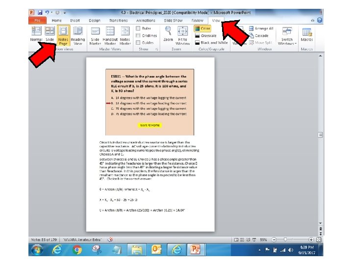
E 5 B 08 -- What is the phase angle between the voltage across and the current through a series RLC circuit if XC is 100 ohms, R is 100 ohms, and XL is 75 ohms? A. B. C. D. 14 degrees with the voltage lagging the current 14 degrees with the voltage leading the current 76 degrees with the voltage lagging the current Work At Home
E 5 B 11 -- What is the phase angle between the voltage across and the current through a series RLC circuit if XC is 25 ohms, R is 100 ohms, and XL is 50 ohms? A. B. C. D. 14 degrees with the voltage lagging the current 14 degrees with the voltage leading the current 76 degrees with the voltage lagging the current 76 degrees with the voltage leading the current Work At Home
E 5 C 15 -- Which point in Figure E 5 -2 best represents the impedance of a series circuit consisting of a 300 ohm resistor and an 18 microhenry inductor at 3. 505 MHz? A. Point 1 B. Point 3 C. Point 7 D. Point 8 Work At Home
E 5 C 16 -- Which point on Figure E 5 -2 best represents the impedance of a series circuit consisting of a 300 ohm resistor and a 19 picofarad capacitor at 21. 200 MHz A. Point 1 B. Point 3 C. Point 7 D. Point 8 Work At Home
E 5 D 15 -- What is the power factor of an R-L circuit having a 45 degree phase angle between the voltage and the current? A. 0. 866 B. 1. 0 C. 0. 5 D. 0. 707 Work At Home
E 5 D 16 -- What is the power factor of an R-L circuit having a 30 degree phase angle between the voltage and the current? A. 1. 73 B. 0. 5 C. 0. 866 D. 0. 577 Work At Home
E 5 D 17 -- How many watts are consumed in a circuit having a power factor of 0. 6 if the input is 200 V AC at 5 amperes? A. 200 watts B. 1000 watts C. 1600 watts D. 600 watts Work At Home
E 5 D 18 -- How many watts are consumed in a circuit having a power factor of 0. 71 if the apparent power is 500 VA? A. 704 W B. 355 W C. 252 W D. 1. 42 m. W Work At Home
E 6 D 11 -- How many turns will be required to produce a 1 -m. H inductor using a core that has an inductance index (AL) value of 523 millihenrys/1000 turns? A. 2 turns B. 4 turns C. 43 turns D. 229 turns Work At Home