Amateur Extra License Class Chapter 7 Radio Signals






- Slides: 169

Amateur Extra License Class Chapter 7 Radio Signals and Measurements

Types of Waveforms • Sine Waves • Most basic type of waveform. • Occur often in nature. • Pendulum. • Weight on spring. • Point on rim of wheel.

Types of Waveforms • Sine waves • Contains only one frequency. • Cycle = One complete set of values before they repeat. • Cycle = One complete rotation of vector (360°). • Frequency = Number of cycles per second. • Period = Time to complete one cycle.

Types of Waveforms • Complex Waveforms • Waveforms that contain more than one frequency. • Regular waves. • More properly called “periodic” waves. • Repeat at a regular interval. • Made up of a fundamental & its harmonics. • Irregular waves. • Non-periodic. • Human speech. • Easily visualized in frequency domain.

Types of Waveforms • Sawtooth Wave • Fundamental and all harmonics. • Amplitude of harmonics decrease with increasing frequency. f 1 + f 2/2 + f 3/3 + f 4/4 + f 5/5 + ………. .

Types of Waveforms • Square Wave • Fundamental and all odd harmonics. • Amplitude of harmonics decrease with increasing frequency. f 1 + f 3/3 + f 5/5 + f 7/7 + f 9/9 + ………. .

Types of Waveforms • Rectangular Wave • Square wave where on & off times are not equal. • Pulse Wave • Rectangular wave where position, width, and/or amplitude of pulses varies. • In radio communications, often narrow pulses with wide gaps between pulses.

AC Waveforms and Measurements • AC Measurements • DC voltmeter/ammeter will read the average voltage/current, which is zero. • With an oscilloscope, it is easy to read the maximum voltage/current. 1 = Peak 2 = Peak-to-Peak 3 = Root-Mean-Square (RMS)

AC Waveforms and Measurements • AC Measurements • An AC current will heat up a resistor. • The amount of DC current that causes the same amount of heating is the root-meansquare (RMS) value. • VRMS = 0. 707 x VPeak 1 = Peak 2 = Peak-to-Peak 3 = Root-Mean-Square (RMS)

AC Waveforms and Measurements • AC Measurements To Calculate Sine Wave Square Wave RMS 0. 707 x Peak 1. 414 x RMS

AC Waveforms and Measurements • AC Power • Voltage & Current In-Phase • PAVG = PRMS = VRMS x IRMS • PPeak = VPeak x IPeak = 2 x PRMS

AC Waveforms and Measurements • Power of Modulated RF Signals • In an unmodulated RF signal, the average power can be calculated from: • PAVG = VRMS 2 / Z

AC Waveforms and Measurements • Power of Modulated RF Signals • If the signal is modulated, the situation is more complex. • CW, FM, & some digital modes have a constant amplitude & the average power is the same as if the carrier was not modulated. • For other modes, it is more useful to use the peak envelope power (PEP) of the signal.

AC Waveforms and Measurements • Power of Modulated RF Signals • Modulated RF signals. • Peak-Envelope-Power (PEP). • Measure peak voltage. • PPEP = (0. 707 x VPeak)2 / RL • Average Power. • Long term average of power output. • Crest Factor. • Ratio of PEP to average power. • SSB typically 2. 5: 1. • 40%

AC Waveforms and Measurements • Electromagnetic Fields • Electric field & magnetic field oscillating at right angles to each other. • Travels through free space at the speed of light. • 186, 000 miles/second. • 300 million meters/second.

AC Waveforms and Measurements • Electromagnetic Fields • Polarization. • Defined by direction of electric field. • Horizontal polarization Horizontal electric field. • Vertical polarization Vertical electric field. • Circular polarization Rotating electric field.

E 8 A 02 -- What type of wave has a rise time significantly faster than its fall time (or vice versa)? A. A cosine wave B. A square wave C. A sawtooth wave D. A sine wave

E 8 A 03 -- What type of wave does a Fourier analysis show to be made up of sine waves of a given fundamental frequency plus all its harmonics? A. A sawtooth wave B. A square wave C. A sine wave D. A cosine wave

E 8 A 05 -- What would be the most accurate way of measuring the RMS voltage of a complex waveform? A. By using a grid dip meter B. By measuring the voltage with a D'Arsonval meter C. By using an absorption wavemeter D. By measuring the heating effect in a known resistor

E 8 A 06 -- What is the approximate ratio of PEPto-average power in a typical single-sideband phone signal? A. 2. 5 to 1 B. 25 to 1 C. 1 to 1 D. 100 to 1

E 8 A 07 -- What determines the PEP-to-average power ratio of a single-sideband phone signal? A. The frequency of the modulating signal B. The characteristics of the modulating signal C. The degree of carrier suppression D. The amplifier gain

Test Equipment • Instruments and Accuracy • Multimeters. • a. k. a. – VOM, DVM, VTVM. • Accuracy expressed in % of full scale. • If accuracy is 2% of full scale on 100 m. A scale, then accuracy is +2 m. A. • Resolution expressed in digits. • Typically 3 ½ digits (0. 000 to 1. 999) • 3 ½ digit 0. 05% resolution. • DO NOT CONFUSE RESOLUTION WITH ACCURACY!

Test Equipment • Instruments and Accuracy • Analog Multimeters. • D’Arsonval movement. • Rotating coil suspended between permanent magnets. • When current flows in coil, coil rotates moving needle across scale. • Coil impedance affects accuracy. • Sensitivity expressed in Ohms/Volt. • 20, 000 Ω/V very good analog meter.

Test Equipment • Instruments and Accuracy • Vacuum Tube Voltmeters (VTVM). • D’Arsonval movement. • Used vacuum tube amplifier to improve sensitivity. • Typically 10 megΩ/V or greater.

Test Equipment • Instruments and Accuracy • Digital Multimeters (DVM). • Digital display. • Use FET amplifier to improve sensitivity. • Typically 10 megΩ/V or greater.

Test Equipment • Instruments and Accuracy • Dip Meters. • Oscillator with fixed external inductor & variable capacitor. • External coil is coupled to an unknown tuned circuit & capacitor adjusted until “dip” occurs. • Read resonant frequency from dial. • General reading only – not precision.

Test Equipment • Instruments and Accuracy • Dip Meters. • Too “loose” coupling will not produce useable dip. • Too “tight” coupling will change resonant frequency of circuit being measured.

Test Equipment • Instruments and Accuracy • Impedance bridges. • By “balancing” the bridge you can determine value of unknown impedance. • Null can be achieved very precisely. • “Antenna analyzers” are actually impedance bridges.

Test Equipment • Instruments and Accuracy • Frequency counter. • Accuracy dependent on time base • Accuracy expressed in parts per million (ppm). • May use a prescaler. • divides a higher frequency signal so a low-frequency counter can display the input frequency

Test Equipment • Instruments and Accuracy • Frequency counter. • Converts input signal into a series of pulses. • Sometimes prescaler used to lower input frequency. • Internal oscillator called the “time base” determines accuracy of counter.

Test Equipment • Instruments and Accuracy • Frequency counter. • Direct-count frequency counter • Counts number of pulses during a known time period. • Frequency is calculated from number of pulses & length of gate pulse. • Period-measuring frequency counter • Counts number of time base pulses during one input signal pulse. • Period is calculated from number of time-base pulses during one input signal pulse. • Improved accuracy for low frequency signals.

Test Equipment • The Oscilloscope • Allows direct observation of high-speed signals & waveforms.

Test Equipment • The Oscilloscope • Displays voltage versus time. • Signal applied to vertical deflection plates. • Sawtooth waveform from time base applied to horizontal deflection plates. • Bandwidth of vertical amplifier determines highest frequency signal that can be displayed. • Sometimes 2 or more vertical amplifiers. • Allows displaying multiple signals simultaneously.

Test Equipment • The Oscilloscope • Uses a probe to connect signal to the vertical amplifier. • Each probe has its own ground lead. • Keep ground leads as short as possible. • Probes are “compensated” to display high frequency waveforms accurately.

Test Equipment Probe Compensated Correctly

Test Equipment Probe Undercompensated

Test Equipment Probe Overcompensated

Test Equipment • The Oscilloscope • Easiest value to read using an oscilloscope is peak-to-peak voltage. • Can also read: • Peak voltage. • Period. • Digital or computer-based Oscopes bandwidth is determined by the sampling rate

Test Equipment • The Digital Oscilloscope • Analog-to-digital conversion speed of the soundcard determines the upper frequency limit for a computer soundcardbased oscilloscope program. • Aliasing – False Signals displayed

Test Equipment • The Digital Oscilloscope • Advantages • Automatic amplitude and frequency numerical readout • Storage of traces for future reference • Manipulation of time base after trace capture

Test Equipment Lissajous Pattern

Test Equipment • The Spectrum Analyzer

Test Equipment • The Spectrum Analyzer • Displays signal amplitude versus frequency. • An oscilloscope displays signals in the time domain. • Horizontal axis displays time. • A spectrum analyzer displays signals in the frequency domain. • Horizontal axis displays frequency. • Narrow filter swept across a range of frequencies.

Test Equipment • The Spectrum Analyzer • Used for checking output of transmitter or amplifier for spurs. • Used for checking transmitter intermodulation distortion (IMD).

Test Equipment • The Spectrum Analyzer

Test Equipment • Logic Analyzer • Displays multiple digital signal states simultaneously.

Test Equipment

Test Equipment

Test Equipment

Test Equipment • Digitizing Signals using a computer soundcard • Determined by the sample rate • Highest frequency is one-half the sample rate

Test Equipment • Two-tone Intermodulation Distortion (IMD) Test • 2 non-harmonically related tones. • ARRL Labs uses 700 Hz & 1900 Hz.

Test Equipment • Transistor Circuit Parameters • Some DC voltage measurements are useful for troubleshooting. • VBE ~ 0. 7 VDC (Silicon) • VBE ~ 0. 3 VDC (Germanium) • VCE ~ 0. 5 x VCC • (If class A amplifier. ) • Other examples in book.

E 4 B 12 -- What is the significance of voltmeter sensitivity expressed in ohms per volt? A. The full scale reading of the voltmeter multiplied by its ohms per volt rating will provide the input impedance of the voltmeter B. When used as a galvanometer, the reading in volts multiplied by the ohms/volt will determine the power drawn by the device under test C. When used as an ohmmeter, the reading in ohms divided by the ohms/volt will determine the voltage applied to the circuit D. When used as an ammeter, the full scale reading in amps divided by ohms/volt will determine the size of shunt needed

E 4 B 08 -- Which of the following is a characteristic of a good DC voltmeter? A. High reluctance input B. Low reluctance input C. High impedance input D. Low impedance input

E 4 B 14 -- What happens if a dip meter is too tightly coupled to a tuned circuit being checked? A. Harmonics are generated B. A less accurate reading results C. Cross modulation occurs D. Intermodulation distortion occurs

E 4 B 02 -- What is an advantage of using a bridge circuit to measure impedance? A. It provides an excellent match under all conditions B. It is relatively immune to drift in the signal generator source C. It is very precise in obtaining a signal null D. It can display results directly in Smith chart format

E 4 A 14 – What is the purpose of the prescaler function on a frequency counter? A. It amplifies the low level signals for more accurate counting B. It multiplies a higher frequency signal so a lowfrequency counter can display the operating frequency C. It prevents oscillation in a low-frequency counter circuit D. It divides a higher frequency signal so a lowfrequency counter can display the input frequency

E 4 B 01 -- Which of the following factors most affects the accuracy of a frequency counter? A. Input attenuator accuracy B. Time base accuracy C. Decade divider accuracy D. Temperature coefficient of the logic

E 4 A 15 -- What is an advantage of a periodmeasuring frequency counter over a directcount type? A. It can run on battery power for remote measurements B. It does not require an expensive highprecision time base C. It provides improved resolution of lowfrequency signals within a comparable time period D. It can directly measure the modulation index of an FM transmitter

E 4 B 05 -- If a frequency counter with a specified accuracy of +/- 10 ppm reads 146, 520, 000 Hz, what is the most the actual frequency being measured could differ from the reading? A. 146. 52 Hz B. 10 Hz C. 146. 52 k. Hz D. 1465. 20 Hz

E 4 B 04 -- If a frequency counter with a specified accuracy of +/- 0. 1 ppm reads 146, 520, 000 Hz, what is the most the actual frequency being measured could differ from the reading? A. 14. 652 Hz B. 0. 1 MHz C. 1. 4652 Hz D. 1. 4652 k. Hz

E 4 B 03 -- If a frequency counter with a specified accuracy of +/- 1. 0 ppm reads 146, 520, 000 Hz, what is the most the actual frequency being measured could differ from the reading? A. 165. 2 Hz B. 14. 652 k. Hz C. 146. 52 Hz D. 1. 4652 MHz

E 4 A 11 – Which of the following is good practice when using an oscilloscope probe? A. Keep the signal ground connection of the probe as short as possible B. Never use a high impedance probe to measure a low impedance circuit C. Never use a DC-coupled probe to measure an AC circuit D. All of these choices are correct

E 4 A 13 – How is the compensation of an oscilloscope probe typically adjusted? A. A square wave is displayed and the probe is adjusted until the horizontal portions of the displayed wave are nearly flat as possible B. A high frequency sine wave is displayed and the probe is adjusted for maximum amplitude C. A frequency standard is displayed and the probe is adjusted until the deflection time is accurate D. A DC voltage standard is displayed and the probe is adjusted until the displayed voltage is accurate

E 4 A 01 – Which of the following parameters determines the bandwidth of a digital or computer-based oscilloscope? A. Input capacitance B. Input impedance C. Sampling rate D. Sample resolution

E 4 A 04 – What determines the upper frequency limit for a computer soundcard-based oscilloscope program? A. Analog-to-digital conversion speed of the soundcard B. Amount of memory on the soundcard C. Q of the interface circuit D. All of these choices are correct

E 4 A 09 – When using a computer’s soundcard input to digitize signals, what is the highest frequency signal that can be digitized without aliasing? A. The same as the sample rate B. One-half the sample rate C. One-tenth the sample rate D. It depends on how the data is stored internally

E 4 A 06 -- What is the effect of aliasing in a digital or computer-based oscilloscope? A. False signals are displayed B. All signals will have a DC soffset C. Calibration of the vertical scale is no longer valid D. False triggering occurs

E 4 A 05 – What might be an advantage of a digital vs. an analog oscilloscope? A. Automatic amplitude and frequency numerical readout B. Storage of traces for future reference C. Manipulation of time base after trace capture D. All of these choice are correct

E 4 A 10 -- Which of the following displays multiple digital signal states simultaneously? A. Network analyzer B. Bit error rate tester C. Modulation monitor D. Logic analyzer

E 4 A 02 -- Which of the following parameters would a spectrum analyzer display on the horizontal and vertical axes? A. RF amplitude and time B. RF amplitude and frequency C. SWR and frequency D. SWR and time

E 4 A 03 -- Which of the following test instruments is used to display spurious signals and/or intermodulation distortion products in an SSB transmitter? A. A wattmeter B. A spectrum analyzer C. A logic analyzer D. A time-domain reflectometer

E 4 A 12 – Which of the following procedures is an important precaution to follow when connecting a spectrum analyzer to a transmitter output? A. Use high quality double shielded coaxial cables to reduce signal losses B. Attenuate the transmitter output going to the spectrum analyzer C. Match the antenna to the load D. All of these choices are correct

E 4 B 10 -- Which of the following describes a method to measure intermodulation distortion in an SSB transmitter? A. Modulate the transmitter with two non-harmonically related radio frequencies and observe the RF output with a spectrum analyzer B. Modulate the transmitter with two non-harmonically related audio frequencies and observe the RF output with a spectrum analyzer C. Modulate the transmitter with two harmonically related audio frequencies and observe the RF output with a peak reading wattmeter D. Modulate the transmitter with two harmonically related audio frequencies and observe the RF output with a logic analyzer

Receiver Performance • Good receiver performance is essential to successful amateur radio communications. • “If you can’t hear ‘em, you can’t work ‘em!” • The topics we will cover in this section will allow you to intelligently compare receivers based on published specifications and test results.

Receiver Performance • Sensitivity and Noise • Receiver sensitivity is a measure of how weak a signal a receiver can receive. • a. k. a. – Minimum discernible signal (MDS). • a. k. a. – Noise floor. • Determined by noise figure and bandwidth of receiver.

Receiver Performance • Sensitivity and Noise • Minimum discernible signal (MDS). • Expressed in d. Bm or μV. • 0 d. Bm = 1 m. W into 50Ω load (≈223 m. V). • Theoretical minimum = -174 d. Bm/Hz. • Noise power at the input of an ideal receiver with a bandwidth of 1 Hz at room temperature. • -174 d. Bm ≈ 4 x 10 -9 m. W ( 4 billionth of a m. W).

Receiver Performance • Sensitivity and Noise • Minimum discernible signal (MDS). • At HF frequencies with an antenna attached, MDS is determined by atmospheric noise. • At VHF frequencies & up, MDS is determined by noise generated inside the front end of the receiver.

Receiver Performance • Sensitivity and Noise • Minimum discernible signal (MDS). • Calculating MDS. • MDS = 10 x log(f. BW) – 174. • Example: What is the MDS of a 400 Hz bandwidth receiver with a noise floor of -174 d. B/Hz? • 10 x log(400) = 26. • MDS = 26 – 174 = -148 d. B.

Receiver Performance • Sensitivity and Noise • Noise figure. • The noise figure of a receiver is the difference in d. B between the noise output of the receiver with no antenna connected and that of an ideal receiver with the same gain & bandwidth. • NF = (Internal Noise) / (Theoretical MDS). • “Figure of merit” of a receiver. • Typically a “good” VHF or UHF preamplifier has a NF ≈ 2 d. B. • Actual noise floor = (Theoretical MDS) + NF.

Receiver Performance • Sensitivity and Noise • Signal-to-noise ratio (SNR). • SNR = (Input signal power) / (Noise power).

Receiver Performance • Image Response • 2 different frequencies, when mixed with the local oscillator frequency will result in a signal at the IF frequency. • Image frequency is the desired frequency plus or minus twice the IF frequency

Receiver Performance • Image Response

Receiver Performance • Image Response • Images can only be reduced by improving the selectivity in the receiver front-end, BEFORE the 1 st mixer. • Pre-selector.

Receiver Performance • Image Response • Image reduction made easier when the image frequency is as far as possible from the desired frequency. • Use as high an IF frequency as possible. • Use a local oscillator frequency above the desired frequency. • Superheterodyne.

Receiver Performance • Selectivity • The ability to select the desired signal & reject all others. • Determined by receiver’s ENTIRE filter chain. • Filters at RF frequency. • Filters at IF frequency. • Filters at AF frequency.

Receiver Performance • Selectivity • Receiver filters. • Band pass filter (pre-selector). • At input to RF pre-amp. • Reduces interference from strong out-of-band signals. • Reduces interference from image response.

Receiver Performance • Selectivity • Receiver filters. • Roofing filter. • Normally located at the input of the 1 st IF amplifier, right after the 1 st mixer. • Typically VHF (70 MHz is common). • Sharp crystal filter wider than bandwidth of widest signal to be received. • Reduces IMD from strong signals outside of the filter passband.

Receiver Performance • Selectivity • Receiver filters. • IF filters. • In final IF stage. • Crystal or mechanical resonator. • Selectable for different operating modes. • 2. 4 k. Hz to 3. 0 k. Hz for SSB. • 500 Hz or less for CW. • 300 Hz to 500 Hz for RTTY or most digital modes. • Typically use soundcard software with 3. 0 k. Hz filter. • Being replaced by DSP filters.

Receiver Performance • Selectivity • Receiver filters. • AF filters. • Primarily external DSP filters. • Can be narrower than IF filters. • Adaptive filters can reduce noise, add notches, etc.

Receiver Performance • Dynamic Range • Blocking Dynamic Range. • As input signal level is increased, a point is reached where output signal no longer increases linearly. • Effects of poor blocking dynamic range. • Gain compression or blocking. • Desensitization. • Nearby signal puts receiver into gain compression, reducing the apparent signal strength of desired signal. • Cross-modulation.

Receiver Performance • Dynamic Range • Blocking Dynamic Range. • Blocking dynamic range is difference between minimum discernible signal (MDS) & level where 1 d. B of gain compression occurs.

Receiver Performance • Dynamic Range • Intercept Points. • Point at which 2 equal strength signals will mix to produce an IMD product of the same strength. • Example: • If a pair of 40 d. Bm signals produce a 3 rd-order IMD signal with a strength of 40 d. Bm, then the receiver has a 3 rd-order intercept point of 40 d. Bm.

Receiver Performance • Dynamic Range • Intercept Points.

Receiver Performance • Dynamic Range • Intercept Points. IP 2 = 2 x PA – PIM IP 3 = (3 x PA – PIM 3) / 2 • The larger IP 2 or IP 3, the better the receiver linearity. • Intermodulation distortion dynamic range measures the ability of a receiver to avoid generating IMD products. IMD DR 3 = 0. 667 x (IP 3 – MDS)

Receiver Performance • Dynamic Range

Receiver Performance • Phase Noise. • Problem became apparent when receivers got better (lower noise floor). • Caused by phase jitter in PLL or DDS oscillator. • Increasing noise level as you tune close to a strong signal. • Noise can interfere with reception of a weak signal close to the strong one.

Receiver Performance • Capture Effect. • FM receivers behave differently than AM/SSB/CW receivers in the presence of QRM. • AM/SSB/CW reception of an S 9 signal seriously degraded by an S 2 interfering signal. • If 2 or more FM signals are on the same frequency, only the strongest one is demodulated. • Capture effect. • Not really a receiver issue. • 3 d. B stronger or so.

Receiver Performance • Dynamic Range • Intermodulation (IMD). • Caused by non-linear circuits or devices. • 3 rd order IMD response extremely important. • 3 rd order subtractive products are near the desired frequency. f. IMD 3 = 2 x f 1 – f 2 or f. IMD 3 = 2 x f 2 – f 1 • Roofing filters help improve IMD. • Help eliminate strong in-band signals near desired signal. • Will NOT help if interfering signal is within the filter passband. • NOT needed for direct conversion (SDR) receivers.

Receiver Performance • SDR Receivers • Largest effect on linearity: • Analog-to-digital converter sample width in bits • Distortion – caused by missing codes in the SDR receiver’s analog-to-digital converter • Overload – when input signals exceed the maximum count values of the analog-to-digital converter

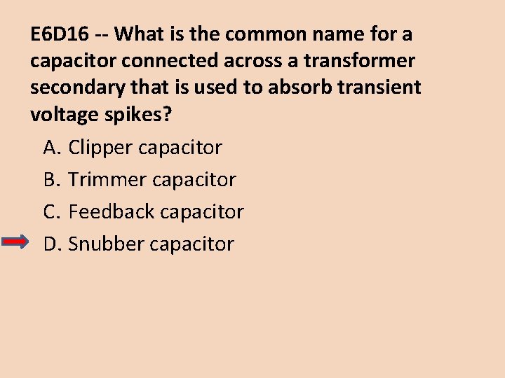
Snubber Capacitor • Snubber Capacitor - a capacitor connected across a transformer secondary that is used to absorb transient voltage spikes?

E 4 C 07 -- What does the MDS of a receiver represent? A. The meter display sensitivity B. The minimum discernible signal C. The multiplex distortion stability D. The maximum detectable spectrum

E 4 C 05 -- What does a value of -174 d. Bm/Hz represent with regard to the noise floor of a receiver? A. The minimum detectable signal as a function of receive frequency B. The theoretical noise at the input of a perfect receiver at room temperature C. The noise figure of a 1 Hz bandwidth receiver D. The galactic noise contribution to minimum detectable signal

E 4 C 15 -- What is usually the primary source of noise that can be heard from an HF receiver with an antenna connected? A. Detector noise B. Induction motor noise C. Receiver front-end noise D. Atmospheric noise

E 4 C 06 -- A CW receiver with the AGC off has an equivalent input noise power density of -174 d. Bm/Hz. What would be the level of an unmodulated carrier input to this receiver that would yield an audio output SNR of 0 d. B in a 400 Hz noise bandwidth? A. 174 d. Bm B. -164 d. Bm C. -155 d. Bm D. -148 d. Bm

E 4 C 04 -- What is the definition of the noise figure of a receiver? A. The ratio of atmospheric noise to phase noise B. The noise bandwidth in Hertz compared to theoretical bandwidth of a resistive network C. The ratio of thermal noise to atmospheric noise D. The ratio in d. B of the noise generated by the receiver compared to theoretical minimum noise

E 6 E 05 -- Which of the following noise figure values is typical of a low-noise UHF preamplifier? A. 2 d. B B. -10 d. B C. 44 d. Bm D. -20 d. Bm

E 4 D 09 -- What is the purpose of the preselector in a communications receiver? A. To store often-used frequencies B. To provide a range of AGC time constants C. To increase rejection of unwanted signals D. To allow selection of the optimum RF amplifier device

E 4 C 02 -- Which of the following portions of a receiver can be effective in eliminating image signal interference? A. A front-end filter or pre-selector B. A narrow IF filter C. A notch filter D. A properly adjusted product detector

E 4 C 09 -- Which of the following choices is a good reason for selecting a high frequency for the design of the IF in a conventional HF or VHF communications receiver? A. Fewer components in the receiver B. Reduced drift C. Easier for front-end circuitry to eliminate image responses D. Improved receiver noise figure

E 4 C 14 – What transmit frequency might generate an image response signal in a receiver tuned to 14. 300 MHz and which uses a 455 k. Hz IF frequency? A. 13. 845 MHz B. 14. 755 MHz C. 14. 445 MHz D. 15. 210 MHz

E 4 C 10 -- Which of the following is a desirable amount of selectivity for an amateur RTTY HF receiver? A. 100 Hz B. 300 Hz C. 6000 Hz D. 2400 Hz

E 4 C 11 -- Which of the following is a desirable amount of selectivity for an amateur SSB phone receiver? A. 1 k. Hz B. 2. 4 k. Hz C. 4. 2 k. Hz D. 4. 8 k. Hz

E 4 C 12 -- What is an undesirable effect of using too wide a filter bandwidth in the IF section of a receiver? A. Output-offset overshoot B. Filter ringing C. Thermal-noise distortion D. Undesired signals may be heard

E 4 C 13 -- How does a narrow-band roofing filter affect receiver performance? A. It improves sensitivity by reducing front end noise B. It improves intelligibility by using low Q circuitry to reduce ringing C. It improves dynamic range by attenuating strong signals near the receive frequency D. All of these choices are correct

E 4 C 17 – Which of the following has the largest effect on an SDR receiver’s linearity? A. CPU register width in bits B. Anti-aliasing input filter bandwidth C. RAM speed used for data storage D. Analog-to-digital converter sample width in bits

E 4 C 16 – Which of the following is caused by missing codes in an SDR receiver’s analog-todigital converter? A. Distortion B. Overload C. Loss of sensitivity D. Excess output level

E 4 C 08 – An SDR receiver is overloaded when input signals exceed what level? A. One-half the maximum sample rate B. One-half the maximum sampling buffer size C. The maximum count values of the analog-todigital converter D. The reference voltage of the analog-to-digital converter

E 4 D 12 -- What is the term for the reduction in receiver sensitivity caused by a strong signal near the received frequency? A. Desensitization B. Quieting C. Cross-modulation interference D. Squelch gain rollback

E 4 D 13 -- Which of the following can cause receiver desensitization? A. Audio gain adjusted too low B. Strong adjacent-channel signals C. Audio bias adjusted too high D. Squelch gain misadjusted

E 4 D 01 -- What is meant by the blocking dynamic range of a receiver? A. The difference in d. B between the noise floor and the level of an incoming signal which will cause 1 d. B of gain compression B. The minimum difference in d. B between the levels of two FM signals which will cause one signal to block the other C. The difference in d. B between the noise floor and the third order intercept point D. The minimum difference in d. B between two signals which produce third order intermodulation products greater than the noise floor

E 4 D 14 -- Which of the following is a way to reduce the likelihood of receiver desensitization? A. Decrease the RF bandwidth of the receiver B. Raise the receiver IF frequency C. Increase the receiver front end gain D. Switch from fast AGC to slow AGC

E 4 D 11 -- Why are third-order intermodulation products created within a receiver of particular interest compared to other products? A. The third-order product of two signals which are in the band of interest is also likely to be within the band B. The third-order intercept is much higher than other orders C. Third-order products are an indication of poor image rejection D. Third-order intermodulation produces three products for every input signal within the band of interest

E 4 D 05 -- What transmitter frequencies would cause an intermodulation-product signal in a receiver tuned to 146. 70 MHz when a nearby station transmits on 146. 52 MHz? A. 146. 34 MHz and 146. 61 MHz B. 146. 88 MHz and 146. 34 MHz C. 146. 10 MHz and 147. 30 MHz D. 173. 35 MHz and 139. 40 MHz

E 4 D 10 -- What does a third-order intercept level of 40 d. Bm mean with respect to receiver performance? A. Signals less than 40 d. Bm will not generate audible third-order intermodulation products B. The receiver can tolerate signals up to 40 d. B above the noise floor without producing third-order intermodulation products C. A pair of 40 d. Bm signals will theoretically generate a third-order intermodulation product with the same level as the input signals D. A pair of 1 m. W input signals will produce a third-order intermodulation product which is 40 d. B stronger than the input signal

E 4 D 02 -- Which of the following describes two problems caused by poor dynamic range in a communications receiver? A. Cross-modulation of the desired signal and desensitization from strong adjacent signals B. Oscillator instability requiring frequent retuning and loss of ability to recover the opposite sideband C. Cross-modulation of the desired signal and insufficient audio power to operate the speaker D. Oscillator instability and severe audio distortion of all but the strongest received signals

E 4 C 01 -- What is an effect of excessive phase noise in the local oscillator section of a receiver? A. It limits the receiver’s ability to receive strong signals B. It reduces receiver sensitivity C. It decreases receiver third-order intermodulation distortion dynamic range D. It can cause strong signals on nearby frequencies to interfere with reception of weak signals

E 4 C 03 -- What is the term for the blocking of one FM phone signal by another, stronger FM phone signal? A. Desensitization B. Cross-modulation interference C. Capture effect D. Frequency discrimination

Interference and Noise • Intermodulation • Non-linear circuits or components can act as mixers to generate signals at the sums & differences of the signals being mixed. • Unwanted signal can be heard along with wanted signal. • Signals can also mix in corroded metal junctions or junctions of dissimilar metals.

Interference and Noise • Transmitter Intermodulation • Signals can mix in the output stage of a transmitter. • The IMD products can be transmitted along with the desired signal. • Low-pass or high-pass filters are NOT effective. • Circulators & isolators are used. • Ferrite devices that act like “one-way valves” for RF. • Cavity resonators.

Interference and Noise • Atmospheric Static • Discharge of static electricity in the atmosphere. • Lightning most visible source of static discharge, but non-lightning discharges occur all the time. • Thunderstorm static louder on lower HF bands (160 m, 80 m, & 40 m). • Can be heard several hundred miles from the source.

Interference and Noise • Atmospheric Static • Static noise can occur without a thunderstorm. • Rain static. • Snow static. • Wind static.

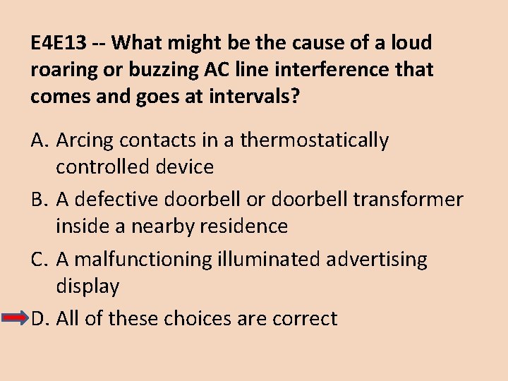
Interference and Noise • AC Line Noise • Man-made noise caused by electric arc. • • Electric motors. Light dimmers. Neon signs. Defective doorbell or doorbell transformer.

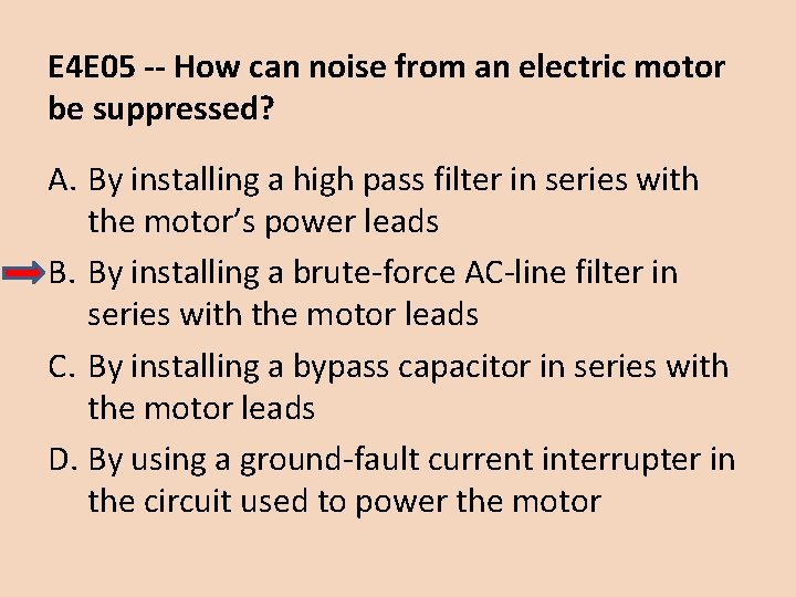
Interference and Noise • AC Line Noise • Install “brute force” AC line filter in series with motor power leads.

Interference and Noise • Locating Noise and Interference Sources • Interference from inside building usually conducted through AC power wiring. • Inside your house. • Outside your house.

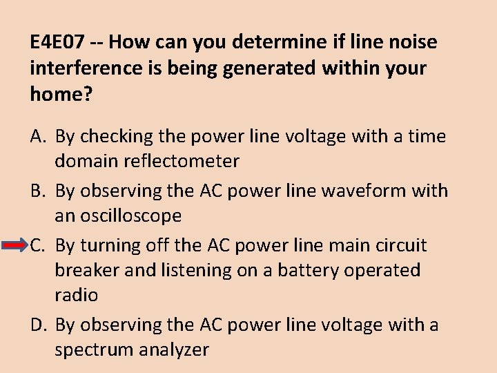
Interference and Noise • Locating Noise and Interference Sources • To determine if noise is generated within your own house, pull main breaker & listen on a battery-operated receiver. • Not FM receiver. • Restore power & make certain noise returns. • Offending device may need to be powered on for a while before generating noise. • Remove power one circuit at a time until noise disappears.

Interference and Noise • Locating Noise and Interference Sources • Interference from outside building usually picked up by antenna or transmission line. • Use “fox hunting” techniques to locate source.

Interference and Noise • Locating Noise and Interference Sources • Your transmitter can couple RF into AC and/or telephone wiring & cause interference to other devices. • Common mode signals. • RF flowing in same direction on both conductors. • TX and RX • Install common mode choke. • Several turns of wire around ferrite toroid core.

Interference and Noise • Locating Noise and Interference Sources • Computer & networking devices. • Unstable modulated or unmodulated signals at specific frequencies. • Switching power supplies. • Series of signals spaced at regular intervals over a wide spectrum. • Touch-controlled devices. • Same as above plus signals that sound like AC hum that may drift slowly across the band.

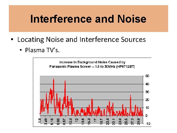
Interference and Noise • Locating Noise and Interference Sources • Plasma TV’s.

Interference and Noise • Automotive Noise • Vehicular System Noise • Ignition system noise. • Pre-1975. • Resistance spark plugs. • High-resistance spark plug cables. • Shielded cables. • 1975 & later. • High resistance plugs & cables can degrade engine performance.

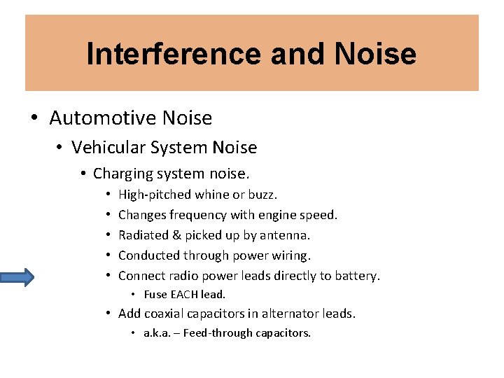
Interference and Noise • Automotive Noise • Vehicular System Noise • Charging system noise. • • • High-pitched whine or buzz. Changes frequency with engine speed. Radiated & picked up by antenna. Conducted through power wiring. Connect radio power leads directly to battery. • Fuse EACH lead. • Add coaxial capacitors in alternator leads. • a. k. a. – Feed-through capacitors.

Interference and Noise • Automotive Noise • Vehicular System Noise • Instrument noise. • Some instruments can generate RF noise. • Install 0. 5 μF coaxial capacitor at the sender element. • Wiper, fuel pump, & other motors can generate RF noise. • Install 0. 25 μF capacitor across the motor winding.

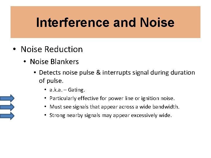
Interference and Noise • Noise Reduction • Noise Blankers • Detects noise pulse & interrupts signal during duration of pulse. • • a. k. a. – Gating. Particularly effective for power line or ignition noise. Must see signals that appear across a wide bandwidth. Strong nearby signals may appear excessively wide.

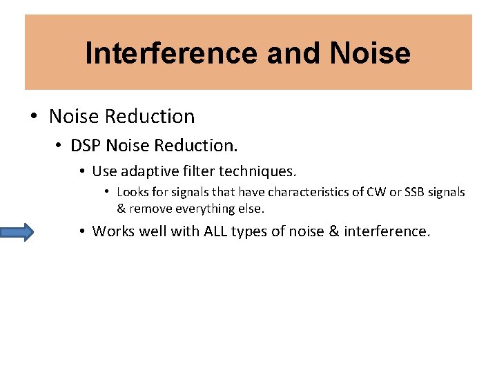
Interference and Noise • Noise Reduction • DSP Noise Reduction. • Use adaptive filter techniques. • Looks for signals that have characteristics of CW or SSB signals & remove everything else. • Works well with ALL types of noise & interference.

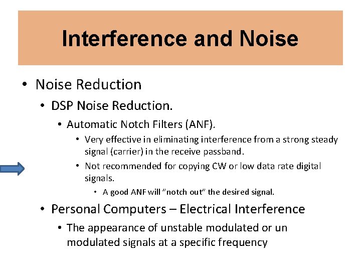
Interference and Noise • Noise Reduction • DSP Noise Reduction. • Automatic Notch Filters (ANF). • Very effective in eliminating interference from a strong steady signal (carrier) in the receive passband. • Not recommended for copying CW or low data rate digital signals. • A good ANF will ”notch out” the desired signal. • Personal Computers – Electrical Interference • The appearance of unstable modulated or un modulated signals at a specific frequency

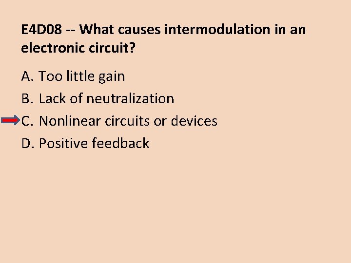
E 4 D 08 -- What causes intermodulation in an electronic circuit? A. Too little gain B. Lack of neutralization C. Nonlinear circuits or devices D. Positive feedback

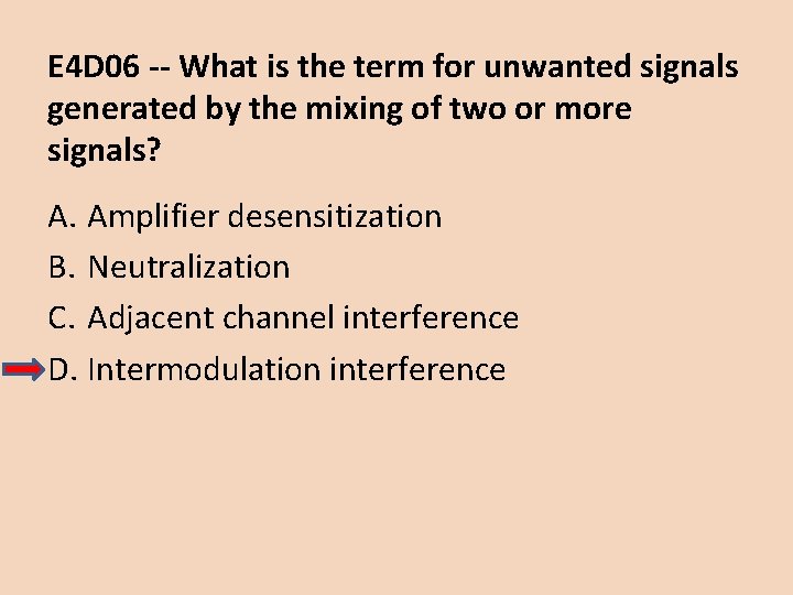
E 4 D 06 -- What is the term for unwanted signals generated by the mixing of two or more signals? A. Amplifier desensitization B. Neutralization C. Adjacent channel interference D. Intermodulation interference

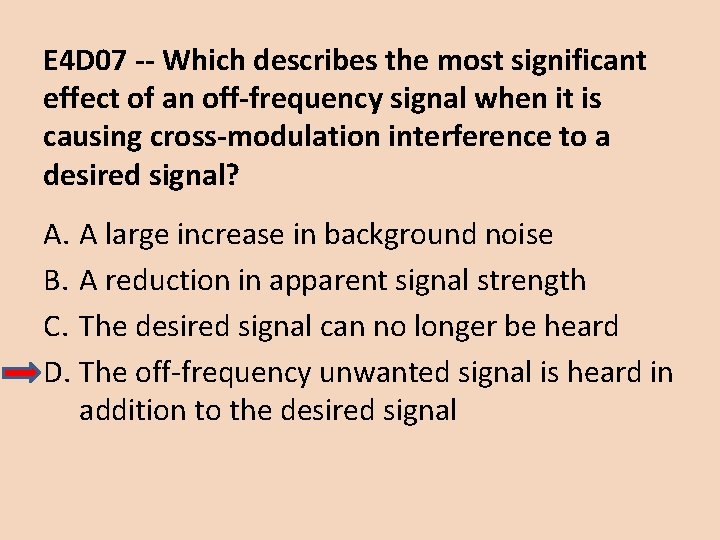
E 4 D 07 -- Which describes the most significant effect of an off-frequency signal when it is causing cross-modulation interference to a desired signal? A. A large increase in background noise B. A reduction in apparent signal strength C. The desired signal can no longer be heard D. The off-frequency unwanted signal is heard in addition to the desired signal

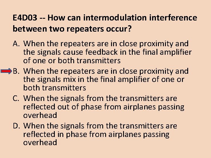
E 4 D 03 -- How can intermodulation interference between two repeaters occur? A. When the repeaters are in close proximity and the signals cause feedback in the final amplifier of one or both transmitters B. When the repeaters are in close proximity and the signals mix in the final amplifier of one or both transmitters C. When the signals from the transmitters are reflected out of phase from airplanes passing overhead D. When the signals from the transmitters are reflected in phase from airplanes passing overhead

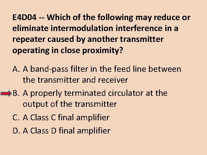
E 4 D 04 -- Which of the following may reduce or eliminate intermodulation interference in a repeater caused by another transmitter operating in close proximity? A. A band-pass filter in the feed line between the transmitter and receiver B. A properly terminated circulator at the output of the transmitter C. A Class C final amplifier D. A Class D final amplifier

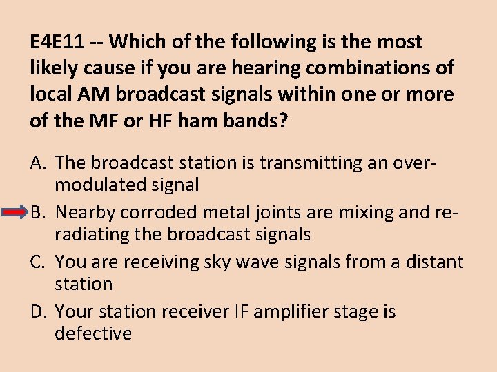
E 4 E 11 -- Which of the following is the most likely cause if you are hearing combinations of local AM broadcast signals within one or more of the MF or HF ham bands? A. The broadcast station is transmitting an overmodulated signal B. Nearby corroded metal joints are mixing and reradiating the broadcast signals C. You are receiving sky wave signals from a distant station D. Your station receiver IF amplifier stage is defective

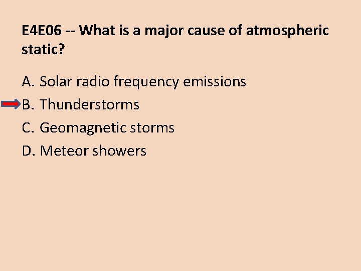
E 4 E 06 -- What is a major cause of atmospheric static? A. Solar radio frequency emissions B. Thunderstorms C. Geomagnetic storms D. Meteor showers

E 4 E 13 -- What might be the cause of a loud roaring or buzzing AC line interference that comes and goes at intervals? A. Arcing contacts in a thermostatically controlled device B. A defective doorbell or doorbell transformer inside a nearby residence C. A malfunctioning illuminated advertising display D. All of these choices are correct

E 4 E 05 -- How can noise from an electric motor be suppressed? A. By installing a high pass filter in series with the motor’s power leads B. By installing a brute-force AC-line filter in series with the motor leads C. By installing a bypass capacitor in series with the motor leads D. By using a ground-fault current interrupter in the circuit used to power the motor

E 6 D 16 -- What is the common name for a capacitor connected across a transformer secondary that is used to absorb transient voltage spikes? A. Clipper capacitor B. Trimmer capacitor C. Feedback capacitor D. Snubber capacitor

E 4 E 07 -- How can you determine if line noise interference is being generated within your home? A. By checking the power line voltage with a time domain reflectometer B. By observing the AC power line waveform with an oscilloscope C. By turning off the AC power line main circuit breaker and listening on a battery operated radio D. By observing the AC power line voltage with a spectrum analyzer

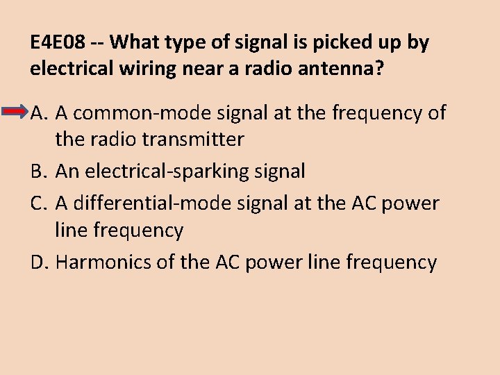
E 4 E 08 -- What type of signal is picked up by electrical wiring near a radio antenna? A. A common-mode signal at the frequency of the radio transmitter B. An electrical-sparking signal C. A differential-mode signal at the AC power line frequency D. Harmonics of the AC power line frequency

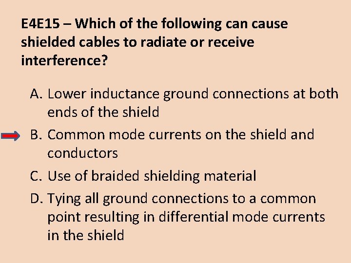
E 4 E 15 – Which of the following can cause shielded cables to radiate or receive interference? A. Lower inductance ground connections at both ends of the shield B. Common mode currents on the shield and conductors C. Use of braided shielding material D. Tying all ground connections to a common point resulting in differential mode currents in the shield

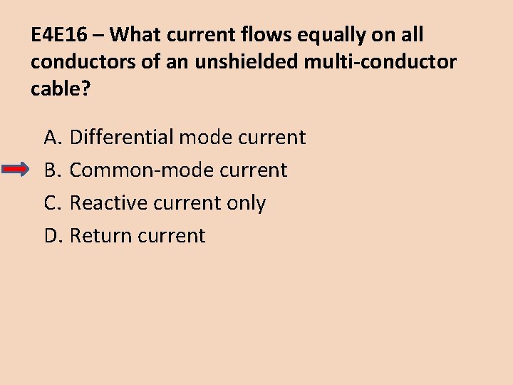
E 4 E 16 – What current flows equally on all conductors of an unshielded multi-conductor cable? A. Differential mode current B. Common-mode current C. Reactive current only D. Return current

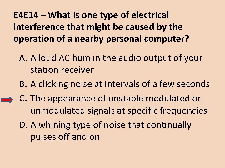
E 4 E 14 – What is one type of electrical interference that might be caused by the operation of a nearby personal computer? A. A loud AC hum in the audio output of your station receiver B. A clicking noise at intervals of a few seconds C. The appearance of unstable modulated or unmodulated signals at specific frequencies D. A whining type of noise that continually pulses off and on

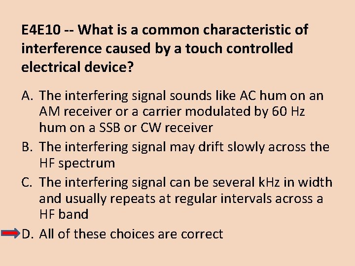
E 4 E 10 -- What is a common characteristic of interference caused by a touch controlled electrical device? A. The interfering signal sounds like AC hum on an AM receiver or a carrier modulated by 60 Hz hum on a SSB or CW receiver B. The interfering signal may drift slowly across the HF spectrum C. The interfering signal can be several k. Hz in width and usually repeats at regular intervals across a HF band D. All of these choices are correct

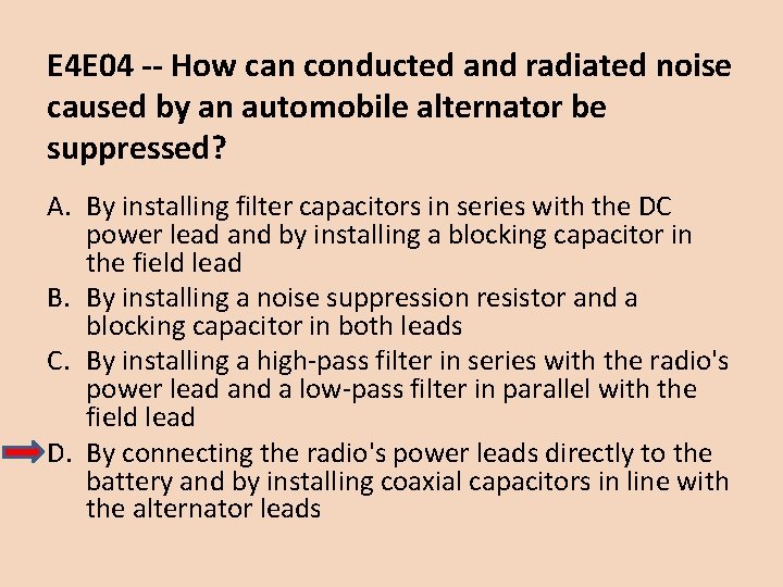
E 4 E 04 -- How can conducted and radiated noise caused by an automobile alternator be suppressed? A. By installing filter capacitors in series with the DC power lead and by installing a blocking capacitor in the field lead B. By installing a noise suppression resistor and a blocking capacitor in both leads C. By installing a high-pass filter in series with the radio's power lead and a low-pass filter in parallel with the field lead D. By connecting the radio's power leads directly to the battery and by installing coaxial capacitors in line with the alternator leads

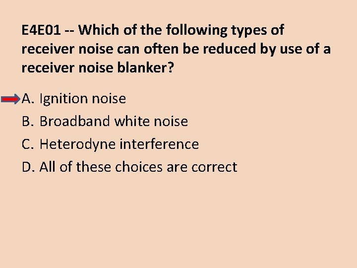
E 4 E 01 -- Which of the following types of receiver noise can often be reduced by use of a receiver noise blanker? A. Ignition noise B. Broadband white noise C. Heterodyne interference D. All of these choices are correct

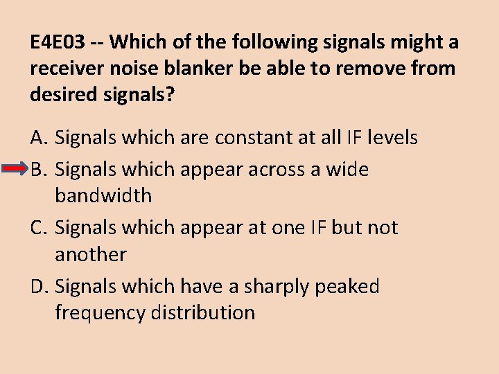
E 4 E 03 -- Which of the following signals might a receiver noise blanker be able to remove from desired signals? A. Signals which are constant at all IF levels B. Signals which appear across a wide bandwidth C. Signals which appear at one IF but not another D. Signals which have a sharply peaked frequency distribution

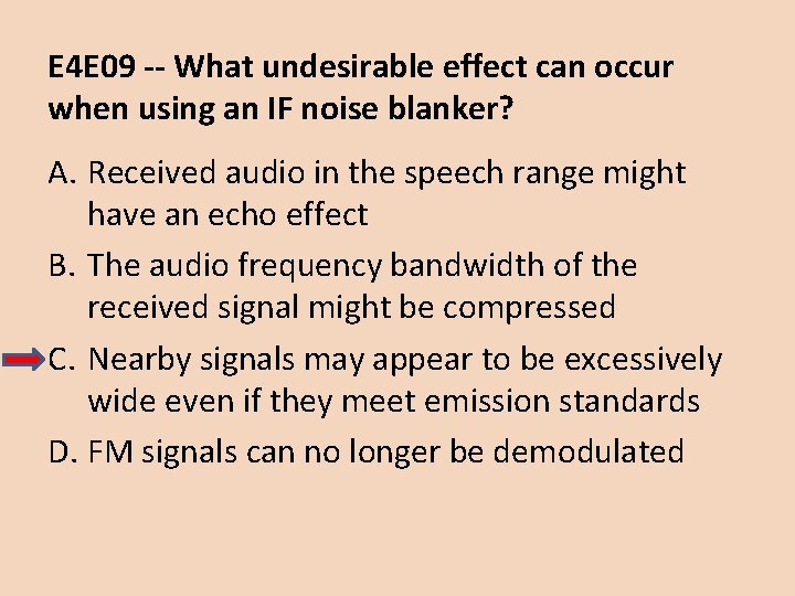
E 4 E 09 -- What undesirable effect can occur when using an IF noise blanker? A. Received audio in the speech range might have an echo effect B. The audio frequency bandwidth of the received signal might be compressed C. Nearby signals may appear to be excessively wide even if they meet emission standards D. FM signals can no longer be demodulated

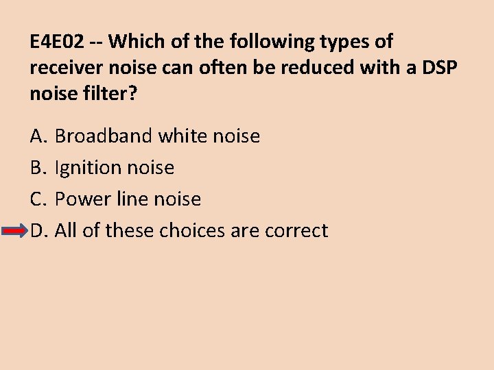
E 4 E 02 -- Which of the following types of receiver noise can often be reduced with a DSP noise filter? A. Broadband white noise B. Ignition noise C. Power line noise D. All of these choices are correct

E 4 E 12 -- What is one disadvantage of using some types of automatic DSP notch-filters when attempting to copy CW signals? A. The DSP filter can remove the desired signal at the same time as it removes interfering signals B. Any nearby signal passing through the DSP system will overwhelm the desired signal C. Received CW signals will appear to be modulated at the DSP clock frequency D. Ringing in the DSP filter will completely remove the spaces between the CW characters

Questions?
 Remote ham radio control
 Tonga ham radio
 Boulder amateur radio club
 Ubnt link calc
 Amateur radio digital communications
 Chelmsford amateur radio society
 Chelmsford amateur radio society
 Chelmsford amateur radio society
 Amateur radio mesh network
 Animals and human language chapter 2
 Language
 Communicative signals and informative signals
 Trunked radio vs conventional radio
 Where may ssb phone be used in amateur bands above 50 mhz?
 Random amateur
 Lust amateur
 Katrina amateur
 Vk com amateur
 Amateur revenge
 Amateur sp
 Amateur sdx
 Japanese amateur hot
 Teacher and student amateur
 Cysterelin
 Telescopio amateur
 New york state amateur hockey association
 Vk amateur
 Driver license class
 Class c license
 Eric hoenigmann
 Extra credit chapter 15
 Mbitr radio class
 Getting a driver license illegally may result in?
 Chapter 1 the new jersey driver license system answers
 Chapter 1 the new jersey driver license system answers
 Signals and systems oppenheim solutions chapter 5
 Signs signals and roadway markings
 A short section of corrugated roadway
 Roadway marking at the left edge of an expressway
 Chapter 3 signs signals and roadway markings
 Chapter 2 signs signals and roadway markings
 A short section of corrugated roadway that warns of hazards
 Chapter 39 plant responses to internal and external signals
 Radazin herbicid
 Nondefining clause
 Res extra commercium
 Siberian massage balsam
 Res commercio
 Retentive tip of the clasp
 Jk audio remotemix sport
 Extra information clauses
 Rekening tamu
 Res extra patrimonium
 Extra sum of squares multiple regression
 30 dollar riddle answer
 Mfl games
 Lesson 1 reteach circumference
 Luxation extra coracoidienne
 Extra y chromosome
 Operazioni triangolari extra ue
 Definition of schizophrenia
 Lesson 8 extra practice quadratic functions
 Zwk01047
 Males with extra y chromosome
 Slidetodoc.com
 Extra lesson antroposofia
 Trabajo extraclase
 Mixed dislocation
 Inter intra extra
 Extramove
 Extra clearance on curves
 Usucapin
 Ira pré renal renal e pós renal
 Intracoronal and extracoronal retainers
 The eight slots on pam's extra large toaster
 Open sans extrabold
 Leks
Leks The extra dopamine released during drug use can
 Medicover zdrowie plus
 Extra markup html
 Ergo vivida vis animi pervicit extra
 George eliot count that day lost
 Coleção extra-axial benigna da infância
 Montserrat extra
 Jeanne nollman
 Senin aşkın bana extra large
 Extra credit anime
 Klinefelter's syndrome
 Extraordinary assumptions
 Hepatic biliary apparatus
 El alfabeto pronunciation
 Extra topicality
 Labore rh
 Extra x
 Extra x
 Dr atiar rahman
 Ocular sign
 Extra credit
 Us extra fancy
 Proximal plate rpd
 Pneumoperitoine scanner
 Uova e colesterolo
 Extra credit avance
 Nibud extra vervoerskosten
 Hora extra
 Extra rapid hardening cement setting time
 Wettability of contact lenses
 Ecu shot type
 Praxis geographie extra lösungen
 How to ask for extra credit
 Extraembryonic membranes in human embryo
 Slide todoc.com
 Ligament of stomach
 Extra information clauses
 Medium voltage range
 Extra material
 Peritoneum anatomy
 Spondyloarthropathy
 Extra ribs
 Extra math
 Droits extra patrimoniaux
 Mesure exophtalmie scanner
 Heuser's membrane
 Patatas rubio extra gruesas
 How to start email to teacher
 Prinales
 Fire safety in extra care
 Extra embryonic membrane in chick
 Extra function
 Extra cell matrix
 Extra brownie points
 Alfabeto pronunciation
 Extra care hagley road
 Percona extra backup
 Cigaronne royal slims
 Lesson 3 extra practice probability of compound events
 Jagman 0103
 What should you do when passing sheep on a road
 Todaysclass
 Package mypackage class first class body
 Difference between abstract class and concrete class
 Mode grouped data
 Class i vs class ii mhc
 Difference between abstract class and concrete class
 Class interval example
 Sd and sdelta
 Response class vs stimulus class
 7 rights of medication administration in order
 Class maths student student1 class student string name
 How to find class boundaries
 In greenfoot, you can cast an actor class to a world class?
 Static class loading and dynamic class loading
 Class 0 esd
 Aggregation vs composition
 Class 2 class 3
 Extends testcase
 Package mypackage class first class body
 Class third class
 Protected in uml
 Component class has composite class as collaborator
 Work based learning license mn
 Wi ems e licensing
 Cssm cisco
 Why does grover want a searcher's license?
 Ga coam master license auction
 Tx ot license verification
 Ingram micro spla
 Altera quartus ii web edition
 Michigan.gov/cg
 South dakota temporary license plates
