Amateur Extra License Class Amateur Extra Class Chapter



- Slides: 166

Amateur Extra License Class

Amateur Extra Class Chapter 6 Electronic Circuits (Part 2)

Digital Signal Processing (DSP) and Software-Defined Radio (SDR) Digital Signal Processing (DSP) • Virtually all modern transceivers include some form of DSP. • DSP allows signal processing that is difficult or impossible to obtain by analog methods. • Digital signals can be regenerated (duplicated) many times without error.

Digital Signal Processing (DSP) and Software-Defined Radio (SDR) Digital Signal Processing (DSP) • Representation of Numbers. • Floating Point. • Floating point is similar to scientific notation. • X = Y x 10 X • Floating point can handle a greater range of numbers. • Floating point is used in computers. • Floating point is not necessary for DSP since the range of numbers is limited by the precision of the ADC.

Digital Signal Processing (DSP) and Software-Defined Radio (SDR) Digital Signal Processing (DSP) • Representation of Numbers. • Fixed Point. • Fixed point represents numbers as a fraction in the range 0 to 1. • Fixed point representation is used for DSP in amateur equipment

Digital Signal Processing (DSP) and Software-Defined Radio (SDR) Digital Signal Processing (DSP) • Procedure: • Convert an analog signal to a series of numbers. • Process the series of numbers mathematically. • Convert the resulting series of numbers back to an analog signal.

Digital Signal Processing (DSP) and Software-Defined Radio (SDR) Digital Signal Processing (DSP) • Sequential Sampling. • The method used to convert an analog signal to a sequence of numbers is called sequential sampling. • The instantaneous value of a signal is determined at regular intervals. • Each signal value is converted to an equivalent number. • Higher sampling rates yields higher accuracy. • More “bits” in the number yields higher accuracy

Digital Signal Processing (DSP) and Software-Defined Radio (SDR) Digital Signal Processing (DSP) • Sequential Sampling. • The higher the sampling rate, the better the accuracy. • The more sampling levels used to determine the number, the better the accuracy. • The number of sampling levels is determined by the number of bits in the number.

Digital Signal Processing (DSP) and Software-Defined Radio (SDR) Digital Signal Processing (DSP) • Sine wave, Alias Sine Wave. • If the sample rate is less than the frequency of the signal being sampled, the result will not match the input signal. • The result will retain the general shape of a sine wave but at a lower frequency. • Downward frequency translation can be useful. • Longer time between samples results in more processing time.

Digital Signal Processing (DSP) and Software-Defined Radio (SDR) Digital Signal Processing (DSP) • Sine wave, Alias Sine Wave. • The Nyquist Sampling Theorem states that to be certain of an accurate representation of the waveform being sampled, the sampling rate must be at least twice the highest frequency in the signal being sampled. • If sampled at less than twice the input frequency a phenomenon called aliasing can occur.

Digital Signal Processing (DSP) and Software-Defined Radio (SDR) Digital Signal Processing (DSP) • Sine wave, Alias Sine Wave. • Aliasing occurs when 2 or more different input signals when sampled at the same rate produce the exact same result.

E 7 F 05 -- How frequently must an analog signal be sampled by an analog-to-digital converter so that the signal can be accurately reproduced? A. At half the rate of the highest frequency component of the signal B. At twice the rate of the highest frequency component of the signal C. At the same rate as the highest frequency component of the signal D. At four times the rate of the highest frequency component of the signal

Digital Signal Processing (DSP) and Software-Defined Radio (SDR) Data Converters. • An analog-to-digital converter (ADC) produces a binary number that is directly proportional to the value of the input voltage. • More bits in binary number higher resolution. • • 8 bits 256 steps. 10 bits 1024 steps. 16 bits 65, 536 steps. 24 bits 16, 777, 216 steps.

Digital Signal Processing (DSP) and Software-Defined Radio (SDR) Data Converters.

Digital Signal Processing (DSP) and Software-Defined Radio (SDR) Data Converters • Adding a small amount of random noise to the input of an ADC is called dithering. • Dithering can improve accuracy.

Digital Signal Processing (DSP) and Software-Defined Radio (SDR) Data Converters • Dithering. • The number generated by an ADC is not exact but is equal to the number that represents the voltage closest to the input voltage.

Digital Signal Processing (DSP) and Software-Defined Radio (SDR) Data Converters • Dithering. • Because of the added noise, one sample may be above the actual voltage while the next sample may be below it. Averaging the samples over time will cancel out the inaccuracies.

Digital Signal Processing (DSP) and Software-Defined Radio (SDR) Data Converters • Even after adding dithering, the digital representation of the analog signal is not exact, resulting in harmonic distortion. • The total harmonic distortion (THD) present in the digitized signal is used as a measurement of the quality of an ADC.

Digital Signal Processing (DSP) and Software-Defined Radio (SDR) Data Converters • When an ADC is used in an SDR receiver, the minimum detectable signal level (MDS) of the receiver is determined by: • The voltage corresponding to the largest value to be digitized (reference voltage). • The number of bits in the number.

Digital Signal Processing (DSP) and Software-Defined Radio (SDR) Data Converters • A digital-to-analog converter (DAC) is a device that produces an output voltage that is directly proportional to value of a binary number. • More bits in binary number higher resolution. • 8 bits 256 steps. • 16 bits 65, 536 steps. • 24 bits 16, 777, 216 steps.

Digital Signal Processing (DSP) and Software-Defined Radio (SDR) Data Converters • Because a DAC has a discrete number of output voltages: • The actual output waveform is not smooth but has a “stair step” appearance, resulting in the output having harmonic distortion. • A low-pass filter is used to reduce the harmonics.

E 7 F 06 -- What is the minimum number of bits required for an analog-to-digital converter to sample a signal with a range of 1 volt at a resolution of 1 millivolt? A. 4 bits B. 6 bits C. 8 bits D. 10 bits

E 7 F 11 -- What sets the minimum detectable signal level for a direct-sampling SDR receiver in the absence of atmospheric or thermal noise? A. Sample clock phase noise B. Reference voltage level and sample width in bits C. Data storage transfer rate D. Missing codes and jitter

E 8 A 04 -- What is "dither" with respect to analog-to-digital converters? A. An abnormal condition where the converter cannot settle on a value to represent the signal B. A small amount of noise added to the input signal to allow more precise representation of a signal over time C. An error caused by irregular quantization step size D. A method of decimation by randomly skipping samples

E 8 A 09 -- How many different input levels can be encoded by an analog-to-digital converter with 8 -bit resolution? A. 8 B. 8 multiplied by the gain of the input amplifier C. 256 divided by the gain of the input amplifier D. 256

E 8 A 10 -- What is the purpose of a low pass filter used in conjunction with a digital-to-analog converter? A. Lower the input bandwidth to increase the effective resolution B. Improve accuracy by removing out-ofsequence codes from the input C. Remove harmonics from the output caused by the discrete analog levels generated D. All of these choices are correct

E 8 A 11 -- Which of the following is a measure of the quality of an analog-to-digital converter? A. Total harmonic distortion B. Peak envelope power C. Reciprocal mixing D. Power factor

Digital Signal Processing (DSP) and Software-Defined Radio (SDR) Fourier Transforms • The process of breaking a complex signal down into the individual frequencies that compose the signal is called Fourier analysis. • e. g. – The Fourier analysis of a square wave shows that it is composed of a fundamental frequency and all odd harmonics.

Digital Signal Processing (DSP) and Software-Defined Radio (SDR) Fourier Transforms • A series of mathematical computations used to perform a Fourier analysis is called a Fourier Transform. • A Fourier transform is the mathematical equivalent of a spectrum analyzer. • The input is a signal in the time domain. • The output represents a signal in the frequency domain.

Digital Signal Processing (DSP) and Software-Defined Radio (SDR) Fourier Transforms • Performing a Fourier analysis requires a LARGE number of calculations. • The Fast Fourier Transform (FFT) is a modern algorithm that reduces the number of calculations required by a factor of 100 or more.

E 7 F 07 -- What function is performed by a Fast Fourier Transform? A. Converting analog signals to digital form B. Converting digital signals to analog form C. Converting digital signals from the time domain to the frequency domain D. Converting 8 -bit data to 16 -bit data

Digital Signal Processing (DSP) and Software-Defined Radio (SDR) Decimation and Interpolation • DSP can perform functions impossible to do with analog circuitry. • e. g. – By using techniques called decimation & interpolation you can shift the frequency of a signal by a non-integer amount.

Digital Signal Processing (DSP) and Software-Defined Radio (SDR) Decimation and Interpolation • Decimation – by removing samples, we can reduce the effective sample rate. • Decimation factor = ratio of input sampling rate to output sampling rate. • Must add an anti-aliasing filter to avoid interpreting high-frequency frequencies as lower frequency signals.

Digital Signal Processing (DSP) and Software-Defined Radio (SDR) Decimation and Interpolation • Interpolation – by adding samples, we can increase the effective sample rate. • Interpolation factor = ratio of input sampling rate to output sampling rate. • No anti-aliasing filter needed.

Digital Signal Processing (DSP) and Software-Defined Radio (SDR) Decimation and Interpolation • For example, to shift the sampling rate by ¾, we would: • Apply an interpolation factor of 3, then • Apply a decimation factor of 4.

E 7 F 08 -- What is the function of decimation? A. Converting data to binary code decimal form B. Reducing the effective sample rate by removing samples C. Attenuating the signal D. Removing unnecessary significant digits

E 7 F 09 -- Why is an anti-aliasing digital filter required in a digital decimator? A. It removes high-frequency signal components which would otherwise be reproduced as lower frequency components B. It peaks the response of the decimator, improving bandwidth C. It removes low frequency signal components to eliminate the need for DC restoration D. It notches out the sampling frequency to avoid sampling errors

Digital Signal Processing (DSP) and Software-Defined Radio (SDR) Systems • A software-defined radio (SDR) system is a radio communication system where components that have been typically implemented in hardware (e. g. mixers, filters, modulators/demodulators, detectors, etc. ) are instead implemented by means of software on a computer or embedded computing devices. • The operation of the radio can be changed simply by loading new software.

Digital Signal Processing (DSP) and Software-Defined Radio (SDR) Systems • The ideal SDR receiver would be to attach an antenna to an analog-to-digital converter (ADC). • Similarly, the ideal SDR transmitter would be to attach a digital-to-analog converter (DAC) to an antenna. • This is not feasible with current technology, so some compromise is necessary.

Digital Signal Processing (DSP) and Software-Defined Radio (SDR) Systems • Some analog processing is still required. • The future is an all-digital radio. • Full-featured SDR transceivers are now commercially available for amateur use.

Digital Signal Processing (DSP) and Software-Defined Radio (SDR) SDR Hardware • Early SDR designs for amateur radio used the following design concept: • A segment of RF spectrum is converted to an audio IF which is digitized & processed. • Lower speed A/D & D/A chips can be used. • Successive approximation or signal-delta ADC. • It is possible to use the computer soundcard for the A/D & D/A functions.

Digital Signal Processing (DSP) and Software-Defined Radio (SDR) SDR Hardware • Current SDR designs for amateur radio use the following design concept: • A segment of the RF spectrum itself is digitized & processed. • Called “Direct Digital Conversion”. • Requires the use of high-speed A/D & D/A chips. • Direct conversion or flash conversion chips. • The maximum size of the segment (maximum receive bandwidth) is determined by the sample rate.

Digital Signal Processing (DSP) and Software-Defined Radio (SDR) SDR Hardware • There are 4 primary types of SDR architecture: 1. Most processing is done in a computer, & the computer soundcard is used for the A/D & D/A functions. • Flex. Radio Systems SDR-1000.

Digital Signal Processing (DSP) and Software-Defined Radio (SDR) SDR Hardware • There are 4 primary types of SDR architecture: 2. Most processing is done in a computer, but the A/D & D/A functions are done in the radio. • Flex. Radio Systems FLEX-5000, FLEX-3000, & FLEX-1500.

Digital Signal Processing (DSP) and Software-Defined Radio (SDR) SDR Hardware • There are 4 primary types of SDR architecture: 3. Most processing is done in the radio with a computer providing the user interface. • Flex. Radio Systems FLEX-6300, FLEX-6400, FLEX -6500, FLEX-6600, & FLEX-6700.

Digital Signal Processing (DSP) and Software-Defined Radio (SDR) SDR Hardware • There are 4 primary types of SDR architecture: 4. All processing done in the radio with conventional knobs & buttons for the user interface. • Flex. Radio Systems FLEX-6400 M & FLEX-6600 M. • Icom IC-7310 & IC-7610. • Elecraft K 4.

E 7 F 01 -- What is meant by direct digital conversion as applied to software defined radios? A. Software is converted from source code to object code during operation of the receiver B. Incoming RF is converted to a control voltage for a voltage controlled oscillator C. Incoming RF is digitized by an analog-to-digital converter without being mixed with a local oscillator signal D. A switching mixer is used to generate I and Q signals directly from the RF input

E 7 F 10 -- What aspect of receiver analog-to-digital conversion determines the maximum receive bandwidth of a Direct Digital Conversion SDR? A. Sample rate B. Sample width in bits C. Sample clock phase noise D. Processor latency

E 8 A 02 -- Which of the following is a type of analog-to-digital conversion? A. Successive approximation B. Harmonic regeneration C. Level shifting D. Phase reversal

E 8 A 08 -- Why would a direct or flash conversion analog-to-digital converter be useful for a software defined radio? A. Very low power consumption decreases frequency drift B. Immunity to out of sequence coding reduces spurious responses C. Very high speed allows digitizing high frequencies D. All of these choices are correct

Digital Signal Processing (DSP) and Software-Defined Radio (SDR) I/Q Modulation and Demodulation • Any sinusiodal signal may be represented by adding a cosine (cos) wave and a sine (sin) wave. • The cosine wave is called the I (in-phase) signal. • The sine wave is called the Q (quadrature) signal. • For DSP it is convenient to consider the I & Q signals separately. • The I & Q signals can be represented mathematically as a complex number: • X = I + j. Q

Digital Signal Processing (DSP) and Software-Defined Radio (SDR) I/Q Modulation and Demodulation • Given the I & Q signals of the modulating waveform & 2 identical RF carriers 90° out of phase, ANY type of modulated signal can be generated. • • • AM DSB SSB FM PM

Digital Signal Processing (DSP) and Software-Defined Radio (SDR) I/Q Modulation and Demodulation • The same techniques, applied in reverse, can be used to demodulate ANY type of modulation. • • • AM DSB SSB FM PM

Digital Signal Processing (DSP) and Software-Defined Radio (SDR) I/Q Modulation and Demodulation • Using I/Q modulation to generate a SSB signal is the mathematical equivalent of the quadrature method of SSB generation. • Generating an audio signal shifted by 90° requires a special type of DSP filter. • Hilbert transform filter.

E 7 F 03 -- What type of digital signal processing filter is used to generate an SSB signal? A. An adaptive filter B. A notch filter C. A Hilbert-transform filter D. An elliptical filter

E 7 F 04 -- What is a common method of generating an SSB signal using digital signal processing? A. Mixing products are converted to voltages and subtracted by adder circuits B. A frequency synthesizer removes the unwanted sidebands C. Varying quartz crystal characteristics emulated in digital form D. Signals are combined in quadrature phase relationship

Filters and Impedance Matching Filter Families and Response Types • Filters are circuits designed to pass certain frequencies and reject others. • R-C circuits. • R-L-C circuits. • A resonant circuit is a simple filter. • Most filters normally pass or reject a wider range of frequencies than a simple resonant circuit.

Filters and Impedance Matching Passive and Active Filters • Passive filters are constructed using only passive components. • • Capacitors. Inductors. Resistors. Crystal. • Passive filters always have some insertion loss.

Filters and Impedance Matching Filter Families and Response Types • Cavity filters are a type of passive filter that use the resonant properties of a conductive tube or box to act as a filter. • Cavity filters have an extremely narrow bandwidth (extremely high Q) and very low loss. • The extremely narrow bandwidth makes them ideal for use in repeater duplexers.

Filters and Impedance Matching Passive and Active Filters • Active filters include some type of amplification. • Because of the amplification, active filters can be constructed to have no insertion loss or even have gain. • Some types of filters can ONLY be built using active components.

Filters and Impedance Matching Passive and Active Filters • Filter Classification. • When discussing filters there are 3 important terms you should be familiar with: • Cut-off frequency. • Passband. • Stopband.

Filters and Impedance Matching Passive and Active Filters • Filter Classification. • The cut-off frequency is the frequency where the response is 3 d. B below the maximum level. • A filter can have either one or two cut-off frequencies.

Filters and Impedance Matching Passive and Active Filters • Filter Classification. • The passband is the range of frequencies where the response is less than 3 d. B below the maximum. • A filter can have either one or two passbands.

Filters and Impedance Matching Passive and Active Filters • Filter Classification. • The stopband is the range of frequencies where the response is more than 3 d. B below the maximum. • A filter can have either one or two stopbands.

Filters and Impedance Matching Passive and Active Filters • Filter Classification. • Filters fall into 4 main categories: • • Low-pass filter (LPF). High-pass filter (HPF). Band-pass filter (BPF). Band-reject filter (BRF).

Filters and Impedance Matching Passive and Active Filters • Filter Classification. • A low-pass filter: • Passes all frequencies below the cut-off frequency. • Attenuates all frequencies above the cut-off frequency. • Has one passband one stopband.

Filters and Impedance Matching Passive and Active Filters • Filter Classification. • A high-pass filter. • Attenuates all frequencies below the cut-off frequency. • Passes all frequencies above the cut-off frequency. • Has one passband one stopband.

Filters and Impedance Matching Passive and Active Filters • Filter Classification. • A band-pass filter. • Has 2 cut-off frequencies. • Passes all frequencies between the cut-off frequencies. • Attenuates all frequencies outside of the cut-off frequencies. • Has one passband two stopbands.

Filters and Impedance Matching Passive and Active Filters • Filter Classification. • A band-reject filter. • Has 2 cut-off frequencies. • Attenuates all frequencies between the cut-off frequencies. • Passes all frequencies outside of the cut-off frequencies. • Has two passbands and one stopbands

Filters and Impedance Matching Passive and Active Filters • Filter Classification. • Band-reject filter. • If the passband of a band-reject filter is narrow, it is called a notch filter.

E 7 C 10 -- Which of the following filters would be the best choice for use in a 2 meter band repeater duplexer? A. A crystal filter B. A cavity filter C. A DSP filter D. An L-C filter

Filters and Impedance Matching Filter Design • Definitions. • Response curve. • The output signal level vs. frequency. • Cut-off frequency = -3 d. B point. • Cut-off transition. • The steepness of the response curve in the transition region between the passband the stopband. • A steeper transition curve a sharper filter. • Ripple. • Variations of the response curve in the passband or outside of the passband.

Filters and Impedance Matching Filter Design • Definitions. • Phase response. • The shift of the signal phase vs. frequency. • Higher attenuation more phase shift. • A linear phase shift means the phase shift is smooth with no ripple as the frequency changes. • A non-linear phase response can distort digital signals. • Ringing. • Oscillations that continue after the signal is removed.

Filters and Impedance Matching Filter Design • A Butterworth filter has: • Minimum ripple in both the passband & the stopband. • A cutoff transition that is smooth but not steep. • A smoothly varying phase response.

Filters and Impedance Matching Filter Design • A Chebyshev filter has: • Ripple in the passband. • A sharper cutoff transition. • Significant phase shift in the passband.

Filters and Impedance Matching Filter Design • An elliptical filter has: • Ripple in both the passband & the stopband. • The sharpest cutoff transition. • Notches positioned at specific frequencies in the stopband to make the transition as sharp as possible.

Filters and Impedance Matching Filter Design • Shape factor is: • Measurement of the “sharpness” of a filter. • The ratio of the -60 d. B bandwidth to the -6 d. B bandwidth. • SF = BW 60 d. B / BW 6 d. B • The closer the ratio is to 1. 0, the sharper the filter. • An ideal filter would have a shape factor of 1. 0.

Filters and Impedance Matching Filter Design • Shape factor. Filter Characteristics 6 d. B Bandwidth 487 Hz, 60 d. B Bandwidth 660 Hz Shape Factor ~1. 36

Filters and Impedance Matching Filter Design • Shape factor. Filter Characteristics 6 d. B Bandwidth 2587 Hz, 60 d. B Bandwidth 2756 Hz Shape Factor ~1. 06

E 7 C 05 -- Which filter type is described as having ripple in the passband a sharp cutoff? A. A Butterworth filter B. An active LC filter C. A passive op-amp filter D. A Chebyshev filter

E 7 C 06 -- What are the distinguishing features of an elliptical filter? A. Gradual passband rolloff with minimal stop band ripple B. Extremely flat response over its pass band with gradually rounded stop band corners C. Extremely sharp cutoff with one or more notches in the stop band D. Gradual passband rolloff with extreme stop band ripple

E 7 C 11 -- Which of the following describes a receiving filter's ability to reject signals occupying an adjacent channel? A. Passband ripple B. Phase response C. Shape factor D. Noise factor

Filters and Impedance Matching Crystal Filters • The IF stages of a superheterodyne receiver require very narrow bandwidth (high Q) filters with sharp transitions to filter out adjacent signals. • The required Q & sharpness cannot be achieved with L -C filters.

Filters and Impedance Matching Crystal Filters • SSB transmitters require very narrow bandwidth (high Q) filters with sharp transitions to filter out the unwanted sideband. • The required Q & sharpness cannot be achieved with L -C filters.

Filters and Impedance Matching Crystal Filters • Crystal lattice filter. • Typically used in SSB transmitters to remove the unwanted sideband.

Filters and Impedance Matching Crystal Filters • Crystal ladder filter. • The bandwidth & response is determined by the frequencies of the individual crystals.

E 7 C 08 -- Which of the following factors has the greatest effect on the bandwidth and response shape of a crystal ladder filter? A. The relative frequencies of the individual crystals B. The DC voltage applied to the quartz crystal C. The gain of the RF stage preceding the filter D. The amplitude of the signals passing through the filter

E 7 C 09 -- What is a crystal lattice filter? A. A power supply filter made with interlaced quartz crystals B. An audio filter made with four quartz crystals that resonate at 1 k. Hz intervals C. A filter using lattice-shaped quartz crystals for high-Q performance D. A filter with narrow bandwidth and steep skirts made using quartz crystals

Break

Filters and Impedance Matching Active Filters • Active filters: • Use an amplifying device. • Are often built using op-amps. • The filter characteristics are determined solely by the external components. • Can be built without inductors. • Smaller & lighter. • Are best suited for audio filtering in receivers.

Filters and Impedance Matching Active Filters • Active filters: • Can be designed either to have no insertion loss or to have gain. • Too much gain or too high a Q can result in a phenomenon called ringing.

Filters and Impedance Matching Active Filters • Ringing. • Unwanted oscillations which cause an output signal to continue after the input signal has ceased is called ringing. • Ringing can occur in both passive and active filters if the Q is too high. • The gain in active filters makes them even more susceptible to ringing.

Filters and Impedance Matching Active Filters • An active audio band-pass filter.

Filters and Impedance Matching Active Filters • Designing an active audio filter: • Pick standard value capacitors. • Low-loss. • Temperature stable. • Polystyrene (? ). • Calculate the resistors.

E 7 G 02 -- What is ringing in a filter? A. An echo caused by a long time delay B. A reduction in high frequency response C. Partial cancellation of the signal over a range of frequencies D. Undesired oscillations added to the desired signal

E 7 G 05 -- How can unwanted ringing and audio instability be prevented in an op-amp RC audio filter circuit? A. Restrict both gain and Q B. Restrict gain, but increase Q C. Restrict Q, but increase gain D. Increase both gain and Q

Filters and Impedance Matching Digital Signal Processing (DSP) Filters • Some of the advantages of DSP filters are: • No tuning is required. • Do not have to worry about selecting standard component values. • Allows for adaptive processing. • Software can recognize & adapt to different signals & conditions to remove noise. • To change the filter characteristics, all you have to do is change the software.

Filters and Impedance Matching Digital Signal Processing (DSP) Filters • Some disadvantages of DSP filters are: • DSP filtering requires computing hardware. • The filter performance is limited by the sampling rate and the resolution of the A-to-D and D-to-A converters used.

Filters and Impedance Matching Digital Signal Processing (DSP) Filters. • Using DSP it is possible to build filters that are impossible to achieve with hardware. • “Brick wall” filters approach shape factors of 1. 0. Filter Characteristics 6 d. B Bandwidth 2587 Hz, 60 d. B Bandwidth 2756 Hz Shape Factor ~1. 06

Filters and Impedance Matching Digital Signal Processing (DSP) Filters • DSP filters are categorized by their response to a very narrow pulse input called an impulse. • Extremely narrow pulses occupy a very wide range of frequencies. • The energy distribution across that range of frequencies is nearly flat.

Filters and Impedance Matching Digital Signal Processing (DSP) Filters. • Finite Impulse Response (FIR) filters.

Filters and Impedance Matching Digital Signal Processing (DSP) Filters. • Finite Impulse Response (FIR) filters. • The output ceases a finite time after the input is removed.

Filters and Impedance Matching Digital Signal Processing (DSP) Filters. • Finite Impulse Response (FIR) filters. • The input is fed to a shift register. • Each stage in shift register is called a tap. • The input signal & output signals of each tap are scaled & added together to create the output signal.

Filters and Impedance Matching Digital Signal Processing (DSP) Filters. • Finite Impulse Response (FIR) filters. • The taps provide incremental signal delays that are used to create the filter function. • More taps sharper filter. • More taps longer delay.

Filters and Impedance Matching Digital Signal Processing (DSP) Filters. • Infinite Impulse Response (IIR) filters.

Filters and Impedance Matching Digital Signal Processing (DSP) Filters. • Infinite Impulse Response (IIR) filters. • The output continues long after the input is removed. • Feed-forward & feedback loops are used to create the filter function.

Filters and Impedance Matching Digital Signal Processing (DSP) Filters. • FIR vs IIR filters. • FIR filters have a linear phase response. • All frequency components are delayed by the same amount. • FIR filters are easier to design. • IIR filters require fewer software components. • Less computational power needed.

E 7 F 02 -- What kind of digital signal processing audio filter might be used to remove unwanted noise from a received SSB signal? A. An adaptive filter B. A crystal-lattice filter C. A Hilbert-transform filter D. A phase-inverting filter

E 7 F 12 -- Which of the following is an advantage of a Finite Impulse Response (FIR) filter vs an Infinite Impulse Response (IIR) digital filter? A. FIR filters can delay all frequency components of the signal by the same amount B. FIR filters are easier to implement for a given set of passband rolloff requirements C. FIR filters can respond faster to impulses D. All these choices are correct

E 7 F 13 -- What is the function of taps in a digital signal processing filter? A. To reduce excess signal pressure levels B. Provide access for debugging software C. Select the point at which baseband signals are generated D. Provide incremental signal delays for filter algorithms

E 7 F 14 -- Which of the following would allow a digital signal processing filter to create a sharper filter response? A. Higher data rate B. More taps C. Complex phasor representations D. Double-precision math routines

Filters and Impedance Matching • If the load & source impedances are not equal, an impedance matching network is needed for maximum power transfer. • Assuming a source impedance of 50Ω, the matching network must: • Cancel the reactive portion of the load impedance. • Transform the resistive component to 50Ω.

Filters and Impedance Matching • L Networks. • L-networks can match virtually any 2 impedances. • The Q of an L-network is fixed. • L-networks are usually only designed to work on a single band. • Which variation to use depends on the ratio of the impedances to be matched.

Filters and Impedance Matching • L Networks. • If the series component of an L-network is an inductor, the network will be a low-pass filter.

Filters and Impedance Matching • L Networks. • If the series component of an L-network is a capacitor, the network will be a high-pass filter.

Filters and Impedance Matching • Pi Networks & Pi-L Networks. • Pi Networks. • A Pi network is the equivalent of 2 L networks connected back -to-back. • A Pi network can be used to match a wide range of load impedances. • The Q of a Pi network can be varied depending on the component values chosen. • A Pi network is used as the output circuit of most tube amplifiers.

Filters and Impedance Matching • Pi Networks & Pi-L Networks. • Pi Networks. • How to adjust a Pi network: • Adjust CTune for minimum plate current. • Adjust CLoad for maximum plate current. • Repeat until the maximum power output is achieved without exceeding the maximum tube plate current rating.

Filters and Impedance Matching • Pi-Networks & Pi-L Networks. • Pi-L network. • A Pi-L network is a Pi network with an inductor or a Pi-L network added to the output. • A Pi-L network provides better harmonic suppression.

Filters and Impedance Matching • T Networks. • • T networks can match a wide range of impedances. T networks lower loss than a pi-network. T networks are used in most antenna tuners. A T network is a high-pass filter and does not provide any harmonic suppression.

E 7 B 09 -- Which of the following describes how the loading and tuning capacitors are to be adjusted when tuning a vacuum tube RF power amplifier that employs a pi-network output circuit? A. The loading capacitor is set to maximum capacitance and the tuning capacitor is adjusted for minimum allowable plate current B. The tuning capacitor is set to maximum capacitance and the loading capacitor is adjusted for minimum plate permissible current C. The loading capacitor is adjusted to minimum plate current while alternately adjusting the tuning capacitor for maximum allowable plate current D. The tuning capacitor is adjusted for minimum plate current, while the loading capacitor is adjusted for maximum permissible plate current

E 7 C 01 -- How are the capacitors and inductors of a low-pass filter Pi-network arranged between the network's input and output? A. Two inductors are in series between the input and output, and a capacitor is connected between the two inductors and ground B. Two capacitors are in series between the input and output and an inductor is connected between the two capacitors and ground C. An inductor is connected between the input and ground, another inductor is connected between the output and ground, and a capacitor is connected between the input and output D. A capacitor is connected between the input and ground, another capacitor is connected between the output and ground, and an inductor is connected between input and output

E 7 C 02 -- Which of the following is a property of a T-network with series capacitors and a parallel shunt inductor? A. It is a low-pass filter B. It is a band-pass filter C. It is a high-pass filter D. It is a notch filter

E 7 C 03 -- What advantage does a Pi-L-network have over a Pi-network for impedance matching between the final amplifier of a vacuum-tube transmitter and an antenna? A. Greater harmonic suppression B. Higher efficiency C. Does not require a capacitor D. Greater transformation range

E 7 C 04 -- How does an impedance-matching circuit transform a complex impedance to a resistive impedance? A. It introduces negative resistance to cancel the resistive part of impedance B. It introduces transconductance to cancel the reactive part of impedance C. It cancels the reactive part of the impedance and changes the resistive part to a desired value D. Reactive currents are dissipated in matched resistances

E 7 C 07 -- Which describes a Pi-L-network used for matching a vacuum tube final amplifier to a 50 -ohm unbalanced output? A. A Phase Inverter Load network B. A Pi-network with an additional series inductor on the output C. A network with only three discrete parts D. A matching network in which all components are isolated from ground

E 7 C 12 -- What is one advantage of a Pi-matching network over an L-matching network consisting of a single inductor and a single capacitor? A. The Q of Pi-networks can be controlled B. L-networks cannot perform impedance transformation C. Pi-networks are more stable D. Pi-networks provide balanced input and output

Power Supplies Unregulated Power Supplies • The most basic type of power supply simply rectifies & filters an AC signal. • The output voltage will contain ripple because the filtering is not 100% effective. • The output voltage will change as the load current changes. • As the current increases, the voltage will drop.

Power Supplies Unregulated Power Supplies • Some type of regulation is required to eliminated the ripple and to keep the output voltage constant. • There are 2 basic types of linear voltage regulators: • Shunt regulators. • Series regulators.

Power Supplies Linear Voltage Regulators • Shunt and series regulators. • Shunt Regulators. • Have very poor efficiency. • The maximum current is drawn from the source all the time regardless of the load.

Power Supplies Linear Voltage Regulators • Shunt and series regulators. • Series Regulators. • Have good efficiency. • Only the current required by the load flows at any given time.

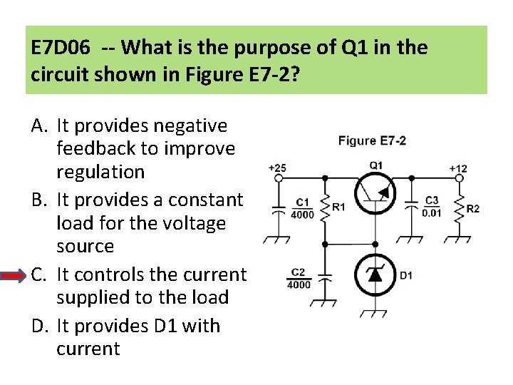
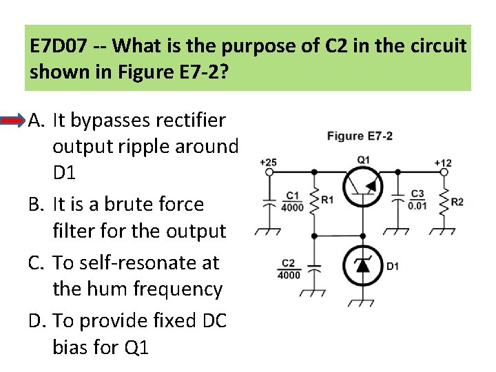
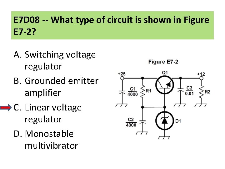
Power Supplies Linear Voltage Regulators • Basic series regulator circuit. • C 1 -- Input by-pass capacitor. • Filters the supply voltage. • C 2 – Hum-filter capacitor. • Bypasses hum around D 1. • C 3 – Output by-pass capacitor. • Often 2 capacitors in parallel. • Large value capacitor to filter output. • Small value capacitor to prevent self-oscillation.

Power Supplies Linear Voltage Regulators • Basic series regulator circuit. • D 1 – Zener diode. • Provides the voltage reference. • Q 1 – Series pass transistor. • Increases the current handling capability of the regulator.

Power Supplies Linear Voltage Regulators • Basic series regulator circuit. • R 1 – Bias resistor. • Provides operating current to D 1. • Provides bias current to Q 1. • R 2 – Load resistor. • Provides a minimum load current for Q 1

Power Supplies Linear Voltage Regulators • IC “ 3 -Terminal” Regulators: • Implement a complete series regulator on a single IC chip. • Provide thermal shutdown protection. • Provide overvoltage protection. • Provide foldback current limiting.

Power Supplies Linear Voltage Regulators • IC “ 3 -Terminal” Regulators. • LM 78 Lxx -- 100 m. A. • LM 78 xx -- 1 Amp. • LM 78 Hxx -- 3 Amps.

Power Supplies Linear Voltage Regulators • Series Regulators. • A minimum voltage must be maintained across the pass transistor for regulation to be maintained. • This is called the drop-out voltage. • If the difference between the input voltage and the desired output voltage (Vin - VOut) drops below the drop-out voltage, then voltage regulation will be lost and the output voltage will drop.

E 7 D 01 -- How does a linear electronic voltage regulator work? A. It has a ramp voltage as its output B. It eliminates the need for a pass transistor C. The control element duty cycle is proportional to the line or load conditions D. The conduction of a control element is varied to maintain a constant output voltage

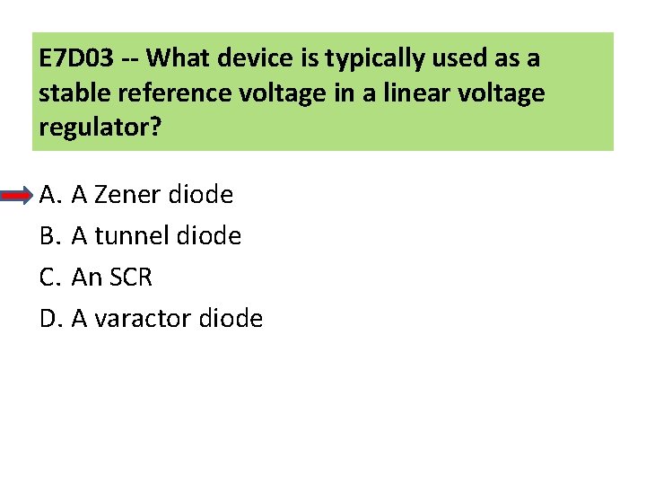
E 7 D 03 -- What device is typically used as a stable reference voltage in a linear voltage regulator? A. A Zener diode B. A tunnel diode C. An SCR D. A varactor diode

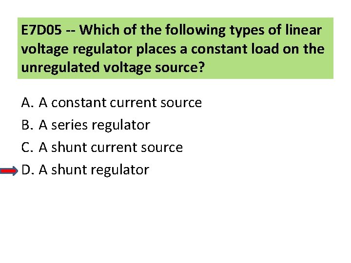
E 7 D 05 -- Which of the following types of linear voltage regulator places a constant load on the unregulated voltage source? A. A constant current source B. A series regulator C. A shunt current source D. A shunt regulator

E 7 D 06 -- What is the purpose of Q 1 in the circuit shown in Figure E 7 -2? A. It provides negative feedback to improve regulation B. It provides a constant load for the voltage source C. It controls the current supplied to the load D. It provides D 1 with current

E 7 D 07 -- What is the purpose of C 2 in the circuit shown in Figure E 7 -2? A. It bypasses rectifier output ripple around D 1 B. It is a brute force filter for the output C. To self-resonate at the hum frequency D. To provide fixed DC bias for Q 1

E 7 D 08 -- What type of circuit is shown in Figure E 7 -2? A. Switching voltage regulator B. Grounded emitter amplifier C. Linear voltage regulator D. Monostable multivibrator

E 7 D 11 -- What is the function of the pass transistor in a linear voltage regulator circuit? A. Permits a wide range of output voltage settings B. Provides a stable input impedance over a wide range of source voltage C. Maintains nearly constant output impedance over a wide range of load current D. Maintains nearly constant output voltage over a wide range of load current

E 7 D 12 -- What is the dropout voltage of an analog voltage regulator? A. Minimum input voltage for rated power dissipation B. Maximum output voltage drops when the input voltage is varied over its specified range C. Minimum input-to-output voltage required to maintain regulation D. Maximum that the output voltage may decrease at rated load

Power Supplies Efficiency and Power Dissipation • Both shunt & series regulators dissipate a significant amount of power as heat. • Series regulators are more efficient because only the current required by the load is drawn. • Efficiency = 100% x POut / Pin

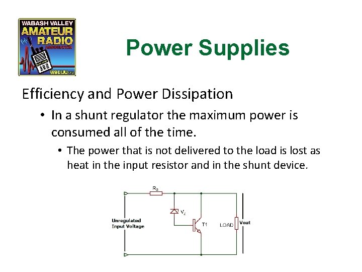
Power Supplies Efficiency and Power Dissipation • In a shunt regulator the maximum power is consumed all of the time. • The power that is not delivered to the load is lost as heat in the input resistor and in the shunt device.

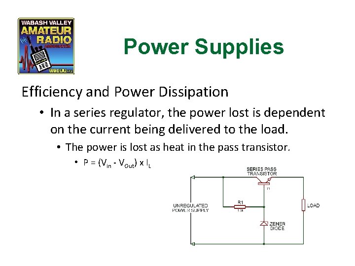
Power Supplies Efficiency and Power Dissipation • In a series regulator, the power lost is dependent on the current being delivered to the load. • The power is lost as heat in the pass transistor. • P = (Vin - VOut) x IL

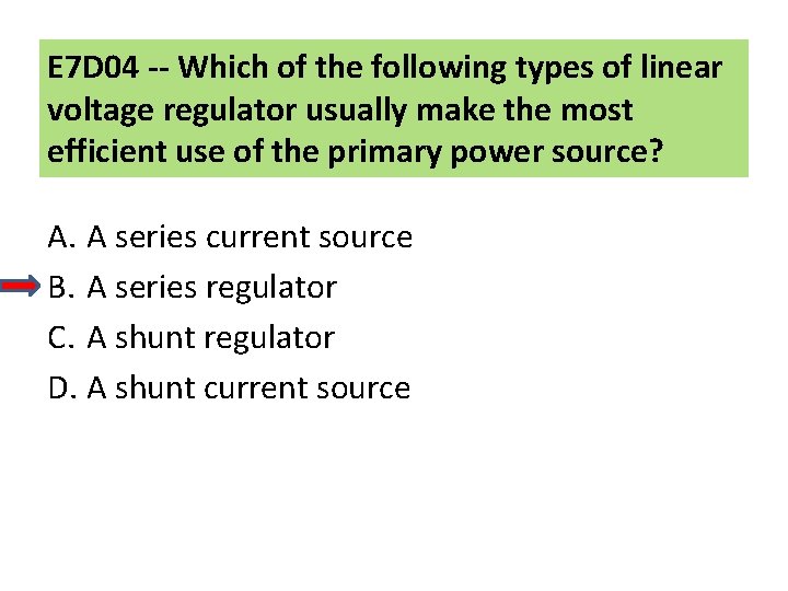
E 7 D 04 -- Which of the following types of linear voltage regulator usually make the most efficient use of the primary power source? A. A series current source B. A series regulator C. A shunt regulator D. A shunt current source

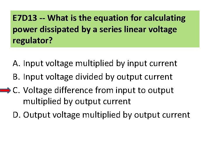
E 7 D 13 -- What is the equation for calculating power dissipated by a series linear voltage regulator? A. Input voltage multiplied by input current B. Input voltage divided by output current C. Voltage difference from input to output multiplied by output current D. Output voltage multiplied by output current

Power Supplies Battery Charging Regulators • Special types of regulators called charge controllers are used to charge re-chargeable batteries. • Required to prevent over-charging or damaging the battery being charged. • The type of regulator used depends on the chemistry of the battery being charged. • Voltage regulator – Lead-Acid. • Current regulator – Ni-Cd, Ni. Mh.

Power Supplies Battery Charging Regulators • The use of the proper charge controller is particularly important in batteries being charged from an intermittent source, such as wind or solar.

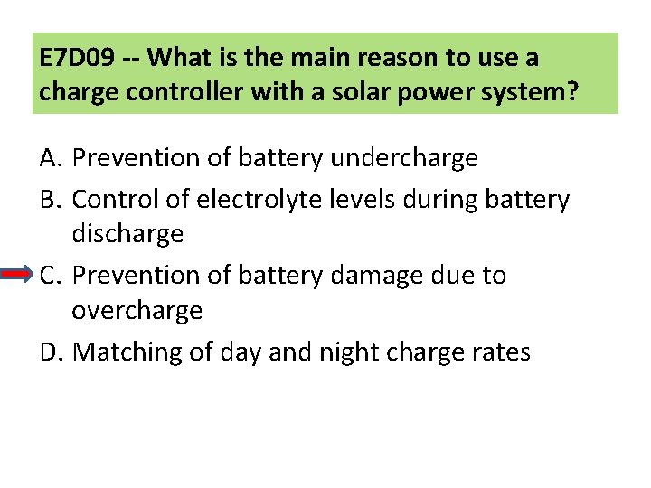
E 7 D 09 -- What is the main reason to use a charge controller with a solar power system? A. Prevention of battery undercharge B. Control of electrolyte levels during battery discharge C. Prevention of battery damage due to overcharge D. Matching of day and night charge rates

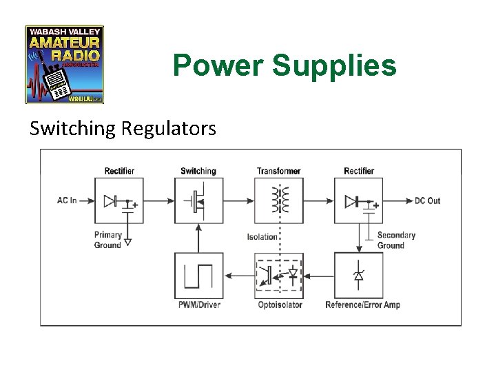
Power Supplies Switching Regulators • The AC input is rectified & switched on/off at a high frequency. • The pulse width is varied to maintain a constant average voltage. • A transformer changes the voltage level. • The output from the transformer is rectified & filtered. • The output is sampled & compared to a reference. • The difference is used to control the pulse width.

Power Supplies Switching Regulators

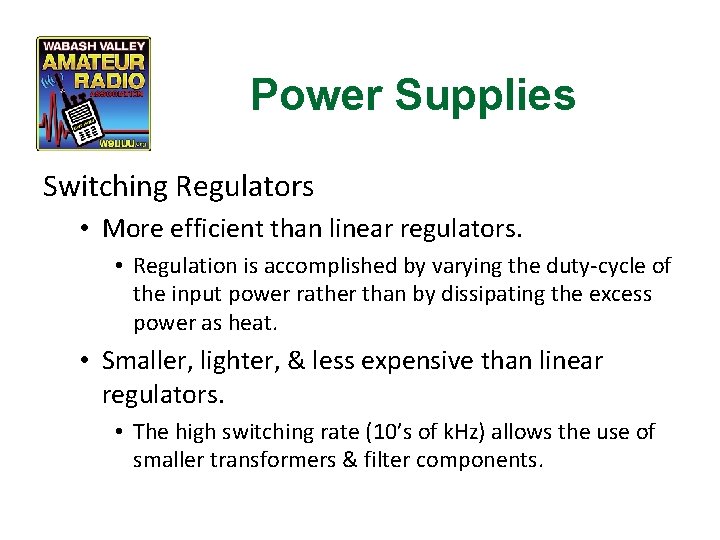
Power Supplies Switching Regulators • More efficient than linear regulators. • Regulation is accomplished by varying the duty-cycle of the input power rather than by dissipating the excess power as heat. • Smaller, lighter, & less expensive than linear regulators. • The high switching rate (10’s of k. Hz) allows the use of smaller transformers & filter components.

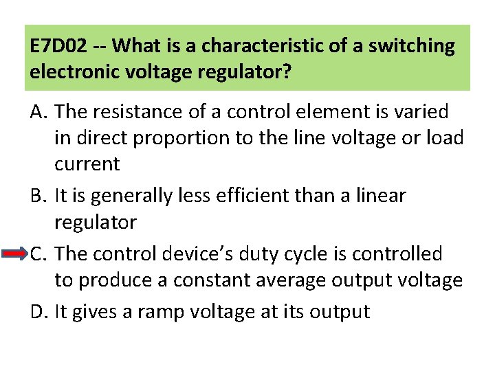
E 7 D 02 -- What is a characteristic of a switching electronic voltage regulator? A. The resistance of a control element is varied in direct proportion to the line voltage or load current B. It is generally less efficient than a linear regulator C. The control device’s duty cycle is controlled to produce a constant average output voltage D. It gives a ramp voltage at its output

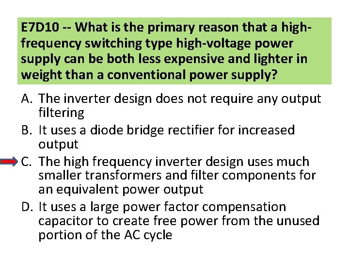
E 7 D 10 -- What is the primary reason that a highfrequency switching type high-voltage power supply can be both less expensive and lighter in weight than a conventional power supply? A. The inverter design does not require any output filtering B. It uses a diode bridge rectifier for increased output C. The high frequency inverter design uses much smaller transformers and filter components for an equivalent power output D. It uses a large power factor compensation capacitor to create free power from the unused portion of the AC cycle

Power Supplies High Voltage Techniques • Bleeder resistors. • The output filter capacitor of a high-voltage power supply can hold a lethal charge long after the power supply power is turned off. • A relatively high value resistor is placed from the power supply output to ground to discharge the filter capacitors after power is removed. • The bleeder resistor also improves voltage regulation by providing a minimum load current to the power supply.

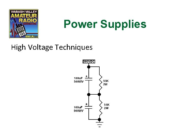
Power Supplies High Voltage Techniques • Voltage equalization resistors. • In high-voltage power supplies, the output filter capacitor often consists of several equal-value capacitors connected in series to create an equivalent capacitor with a higher voltage rating. • Variations in the values of each capacitor results in the voltages across each capacitor not being equal. • Equal-value resistors are placed in parallel with each capacitor to equalize the voltages. • These resistors also serve as the bleeder resistor.

Power Supplies High Voltage Techniques

Power Supplies High Voltage Techniques • Step-start. • When power is first applied to a high-voltage, highpower supply, there is an initial inrush of current until the filter capacitors have charged. This high current can stress the power transformer, the rectifiers, and the filter capacitors. • To limit this inrush of current a technique called stepstart is used.

Power Supplies High Voltage Techniques • Step-start. • A resistor is placed in series with the transformer primary winding. • After a short delay, a relay shorts the resistor. • This allows the capacitors to charge more slowly and limits the inrush current.

E 7 D 14 -- What is the purpose of connecting equal-value resistors across power supply filter capacitors connected in series? A. Equalize the voltage across each capacitor B. Discharge the capacitors when voltage is removed C. Provide a minimum load on the supply D. All these choices are correct

E 7 D 15 -- What is the purpose of a step-start circuit in a high-voltage power supply? A. To provide a dual-voltage output for reduced power applications B. To compensate for variations of the incoming line voltage C. To allow for remote control of the power supply D. To allow the filter capacitors to charge gradually

Questions?

Amateur Extra Class Next Week Chapter 7 Radio Signals and Measurements