
Short Course for the Amateur Radio Technician License





- Slides: 111
Short Course for the Amateur Radio Technician License Element 2 Richie Allen KC 5 NZR kc 5 nzr@arrl. net Sponsored by: Albuquerque Amateur Radio Club
Who is the Amateur Operator? • • History of the Amateur Service Innovations Public Service Real Life Examples 2
Video Amateur Radio Today 3
Course Syllabus (NYT pages 12, 13) T 1 FCC Rules T 2 Operating Procedures T 3 Propagation T 4 Ham Radio Practices T 5 Electrical Principles T 6 Circuit Components T 7 Practical Circuits T 8 Signals and Emissions T 9 Antennas & Feedlines T 0 RF Safety 9 Questions 5 Questions 3 Questions 4 Questions 3 Questions 2 Questions 35 total questions on exam 4
EXAM (element 2) • 35 questions from the question pool in chapter 12 of NYT • Administered by a Volunteer Examiner (VE) team • Test fee $12 as of 1/1/2003 • 1: 00 PM Sunday, right here • Bring: photo ID, second ID, exam fee, pencils, calculator • Your instructor is not a member of the VE team • There are other exam opportunities, but this course is designed to optimize your short term retention of the material 5
License Classes • Technician with code • General • Extra 6
Federal Communications Commission FCC • Governing agency of Amateur Radio • Part 97 Principles of the amateur service • Increase number of trained radio operators • Improve international good will Terms • Amateur Station • Control operator • License grant • License class • License term • Grace period • Form 605 7
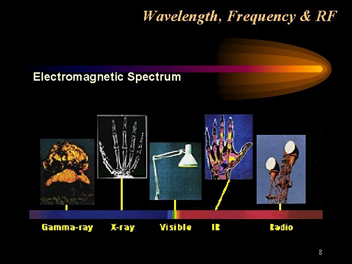
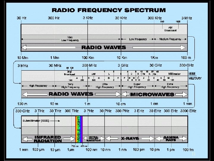
Wavelength, Frequency & RF Electromagnetic Spectrum 8
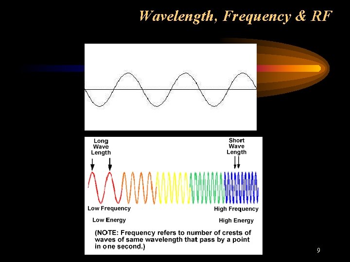
Wavelength, Frequency & RF 9
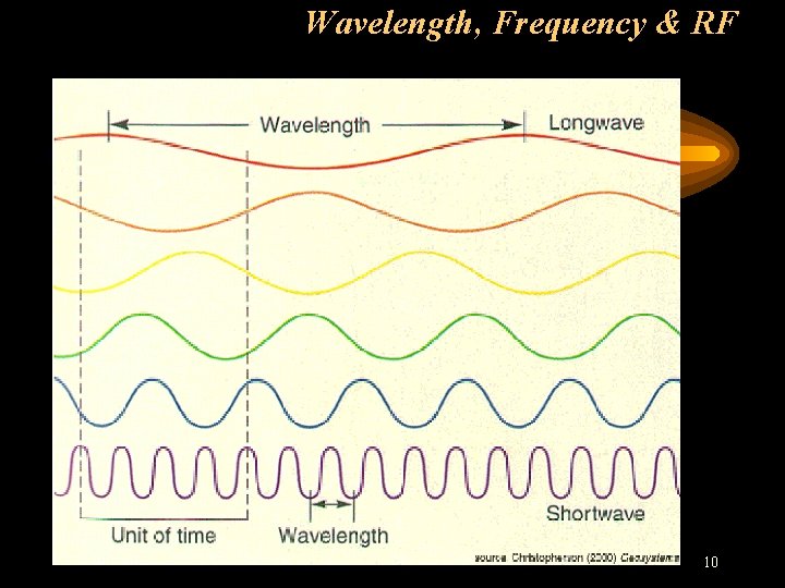
Wavelength, Frequency & RF 10
11
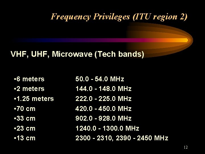
Frequency Privileges (ITU region 2) VHF, UHF, Microwave (Tech bands) • 6 meters • 2 meters • 1. 25 meters • 70 cm • 33 cm • 23 cm • 13 cm 50. 0 - 54. 0 MHz 144. 0 - 148. 0 MHz 222. 0 - 225. 0 MHz 420. 0 - 450. 0 MHz 902. 0 - 928. 0 MHz 1240. 0 - 1300. 0 MHz 2300 - 2310, 2390 - 2450 MHz 12
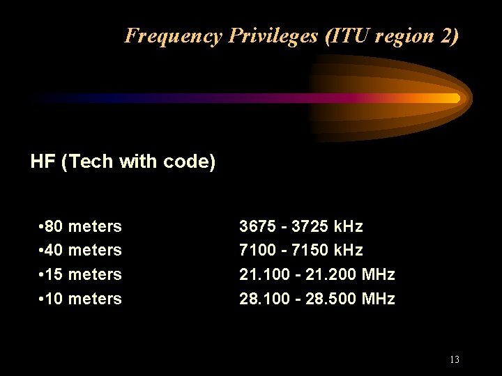
Frequency Privileges (ITU region 2) HF (Tech with code) • 80 meters • 40 meters • 15 meters • 10 meters 3675 - 3725 k. Hz 7100 - 7150 k. Hz 21. 100 - 21. 200 MHz 28. 100 - 28. 500 MHz 13
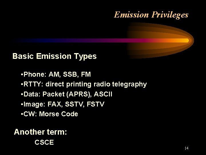
Emission Privileges Basic Emission Types • Phone: AM, SSB, FM • RTTY: direct printing radio telegraphy • Data: Packet (APRS), ASCII • Image: FAX, SSTV, FSTV • CW: Morse Code Another term: CSCE 14
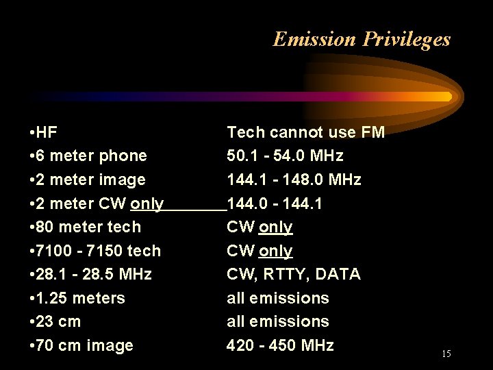
Emission Privileges • HF • 6 meter phone • 2 meter image • 2 meter CW only • 80 meter tech • 7100 - 7150 tech • 28. 1 - 28. 5 MHz • 1. 25 meters • 23 cm • 70 cm image Tech cannot use FM 50. 1 - 54. 0 MHz 144. 1 - 148. 0 MHz 144. 0 - 144. 1 CW only CW, RTTY, DATA all emissions 420 - 450 MHz 15
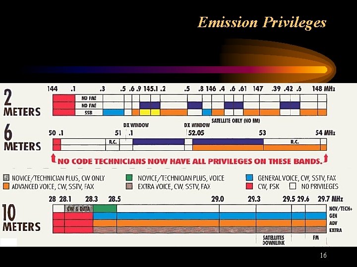
Emission Privileges 16
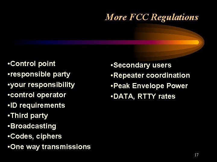
More FCC Regulations • Control point • responsible party • your responsibility • control operator • ID requirements • Third party • Broadcasting • Codes, ciphers • One way transmissions • Secondary users • Repeater coordination • Peak Envelope Power • DATA, RTTY rates 17
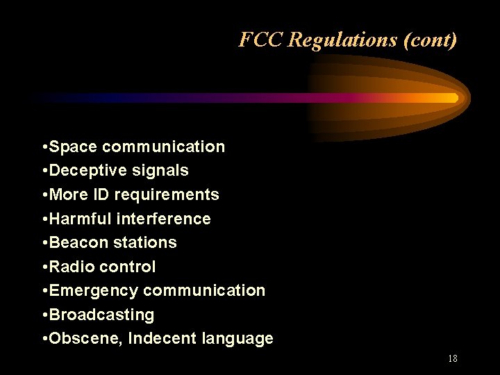
FCC Regulations (cont) • Space communication • Deceptive signals • More ID requirements • Harmful interference • Beacon stations • Radio control • Emergency communication • Broadcasting • Obscene, Indecent language 18
Operating Procedures • Before transmitting • Emergencies • Using appropriate frequency • Testing a transmitter • Morse code “CQ”, “DE” 19
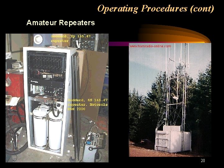
Operating Procedures (cont) Amateur Repeaters 20
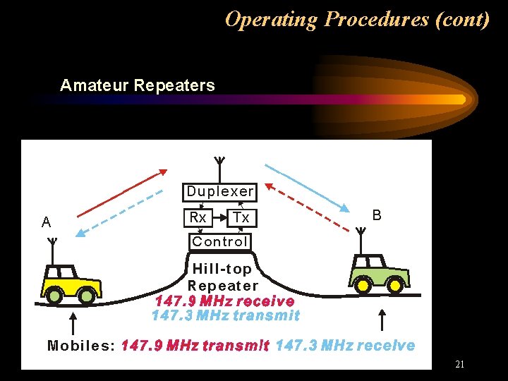
Operating Procedures (cont) Amateur Repeaters 21
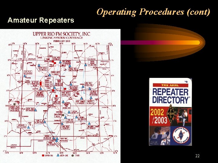
Amateur Repeaters Operating Procedures (cont) 22
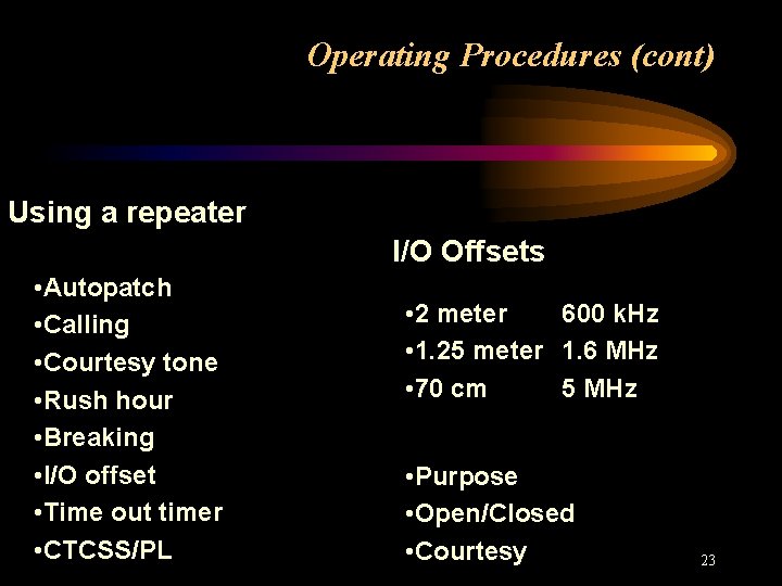
Operating Procedures (cont) Using a repeater I/O Offsets • Autopatch • Calling • Courtesy tone • Rush hour • Breaking • I/O offset • Time out timer • CTCSS/PL • 2 meter 600 k. Hz • 1. 25 meter 1. 6 MHz • 70 cm 5 MHz • Purpose • Open/Closed • Courtesy 23
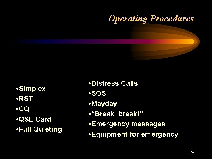
Operating Procedures • Simplex • RST • CQ • QSL Card • Full Quieting • Distress Calls • SOS • Mayday • “Break, break!” • Emergency messages • Equipment for emergency 24
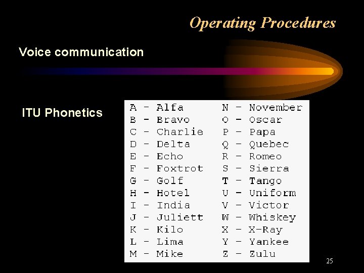
Operating Procedures Voice communication ITU Phonetics 25
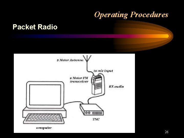
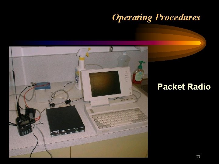
Operating Procedures Packet Radio 26
Operating Procedures Packet Radio 27
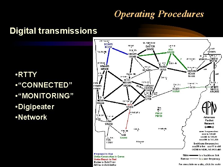
Operating Procedures Digital transmissions • RTTY • “CONNECTED” • “MONITORING” • Digipeater • Network 28
Operating Procedures • CW & SSB on HF • Answering CQ on RTTY • Operating on commercial aircraft • Operating away from home 29
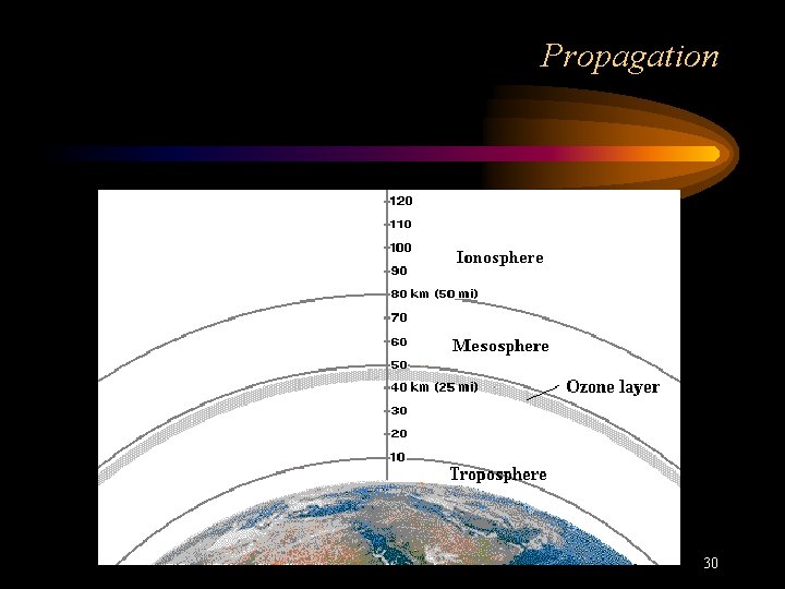
Propagation 30
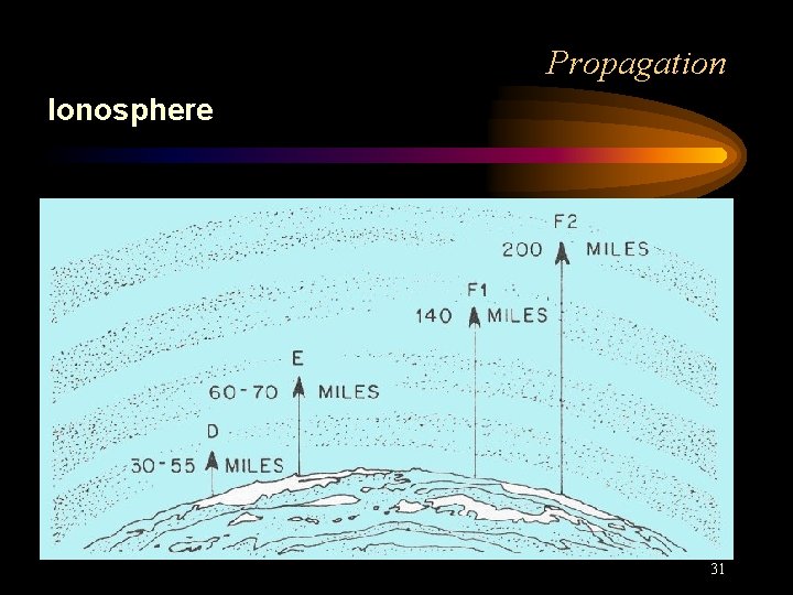
Propagation Ionosphere 31
Propagation • Line of sight • Ionosphere regions • UV radiation • Reflections • Ducting • Inversion • EME • Satellites 32
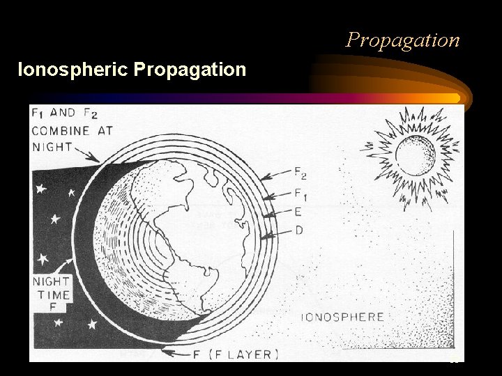
Propagation Ionospheric Propagation 33
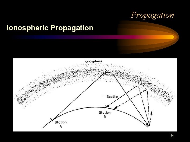
Propagation Ionospheric Propagation 34
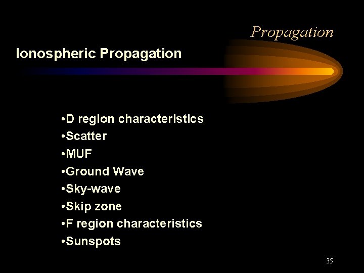
Propagation Ionospheric Propagation • D region characteristics • Scatter • MUF • Ground Wave • Sky-wave • Skip zone • F region characteristics • Sunspots 35
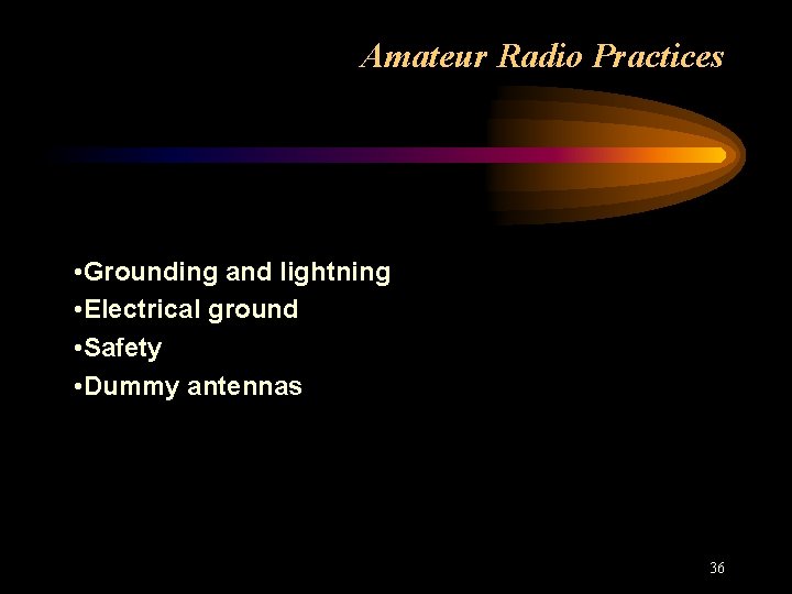
Amateur Radio Practices • Grounding and lightning • Electrical ground • Safety • Dummy antennas 36
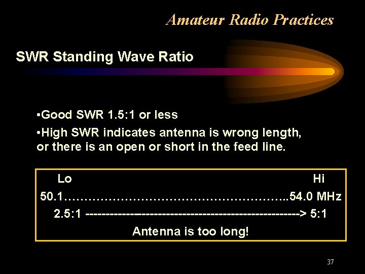
Amateur Radio Practices SWR Standing Wave Ratio • Good SWR 1. 5: 1 or less • High SWR indicates antenna is wrong length, or there is an open or short in the feed line. Lo Hi 50. 1………………………. . 54. 0 MHz 2. 5: 1 ---------------------------> 5: 1 Antenna is too long! 37
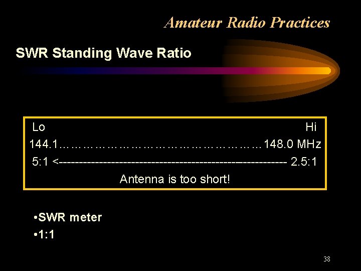
Amateur Radio Practices SWR Standing Wave Ratio Lo Hi 144. 1……………………… 148. 0 MHz 5: 1 <----------------------------- 2. 5: 1 Antenna is too short! • SWR meter • 1: 1 38
Amateur Radio Practices Test equipment • Voltmeter • Ammeter • RF wattmeter • Multimeter • Directional wattmeter • Fuses 39
Amateur Radio Practices Radio Frequency Interference • Receiver overload • Harmonic Radiation • Low pass filter • High pass filter 40
Electrical Principles • Hz - k. Hz • ma - ampere • Ampere • Volt • Conductors & insulators • Open & short circuits • Resistance & Resistors • Inductance & Inductors • Capacitance & Capacitors • Parallel & Series connections 41
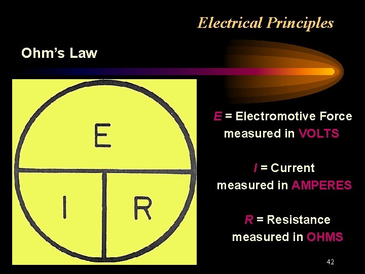
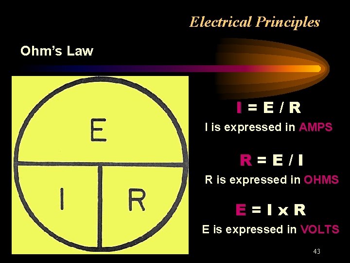
Electrical Principles Ohm’s Law E = Electromotive Force measured in VOLTS I = Current measured in AMPERES R = Resistance measured in OHMS 42
Electrical Principles Ohm’s Law I=E/R I is expressed in AMPS R=E/I R is expressed in OHMS E=Ix. R E is expressed in VOLTS 43
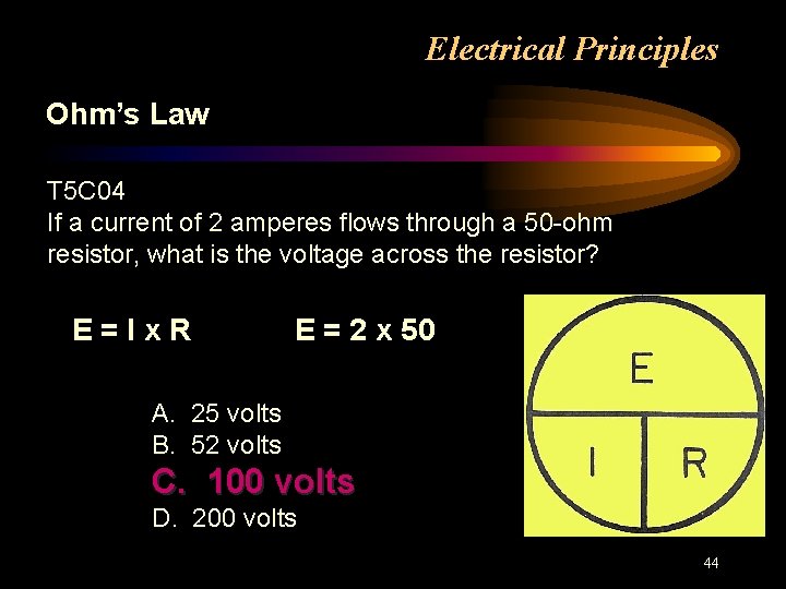
Electrical Principles Ohm’s Law T 5 C 04 If a current of 2 amperes flows through a 50 -ohm resistor, what is the voltage across the resistor? E=Ix. R E = 2 x 50 A. 25 volts B. 52 volts C. 100 volts D. 200 volts 44
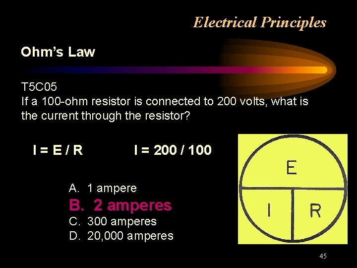
Electrical Principles Ohm’s Law T 5 C 05 If a 100 -ohm resistor is connected to 200 volts, what is the current through the resistor? I=E/R I = 200 / 100 A. 1 ampere B. 2 amperes C. 300 amperes D. 20, 000 amperes 45
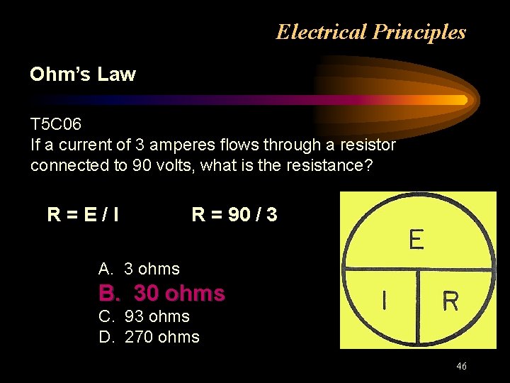
Electrical Principles Ohm’s Law T 5 C 06 If a current of 3 amperes flows through a resistor connected to 90 volts, what is the resistance? R=E/I R = 90 / 3 A. 3 ohms B. 30 ohms C. 93 ohms D. 270 ohms 46
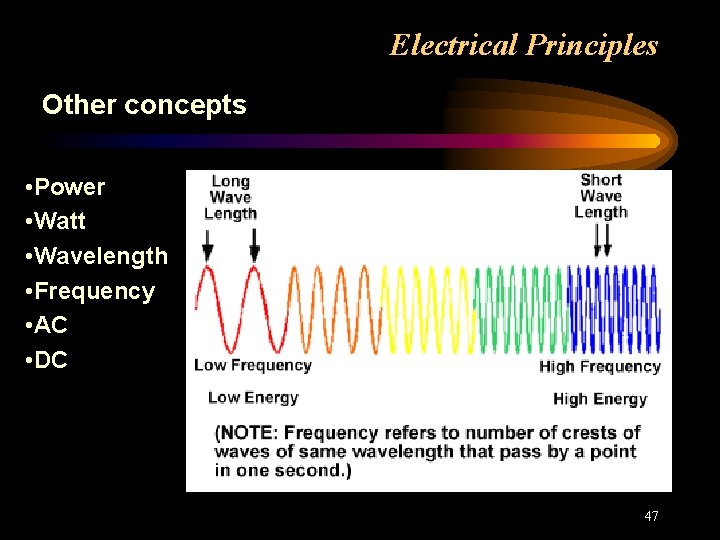
Electrical Principles Other concepts • Power • Watt • Wavelength • Frequency • AC • DC 47
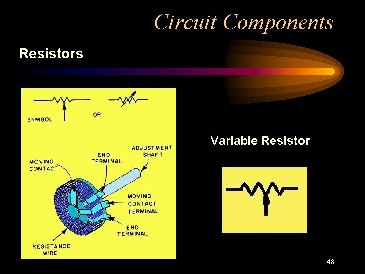
Circuit Components Resistors Variable Resistor 48
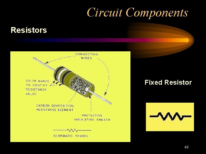
Circuit Components Resistors Fixed Resistor 49
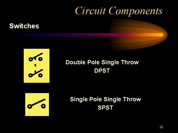
Circuit Components Switches Double Pole Single Throw DPST Single Pole Single Throw SPST 50
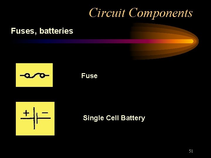
Circuit Components Fuses, batteries Fuse Single Cell Battery 51
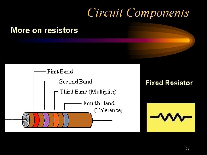
Circuit Components More on resistors Fixed Resistor 52
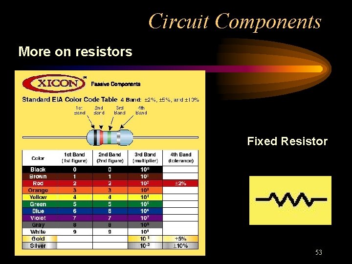
Circuit Components More on resistors Fixed Resistor 53
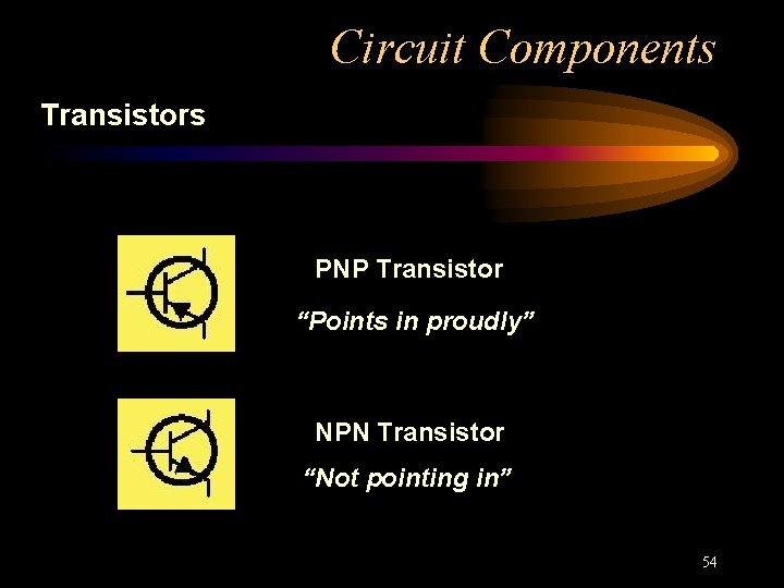
Circuit Components Transistors PNP Transistor “Points in proudly” NPN Transistor “Not pointing in” 54
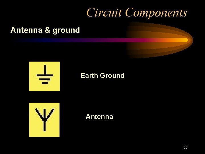
Circuit Components Antenna & ground Earth Ground Antenna 55
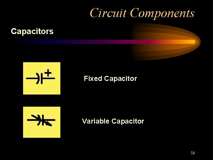
Circuit Components Capacitors Fixed Capacitor Variable Capacitor 56
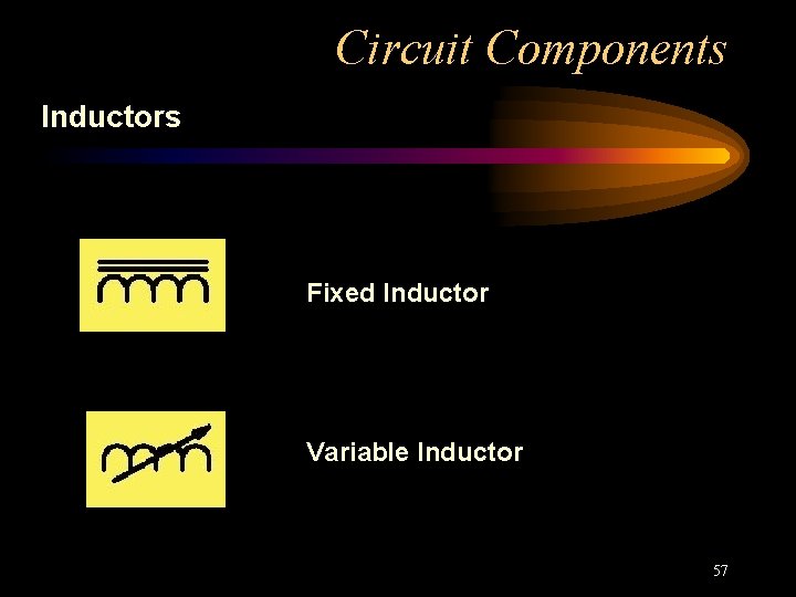
Circuit Components Inductors Fixed Inductor Variable Inductor 57
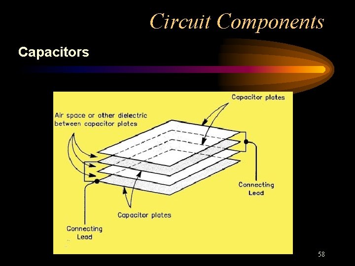
Circuit Components Capacitors 58
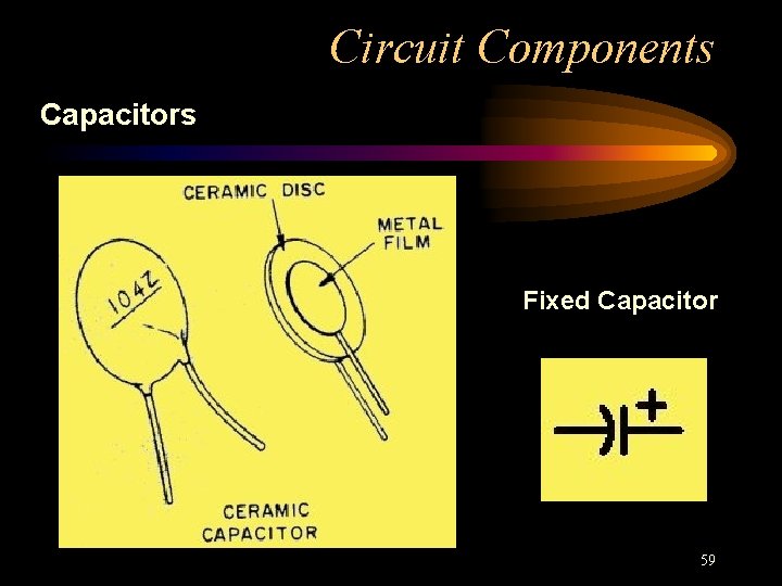
Circuit Components Capacitors Fixed Capacitor 59
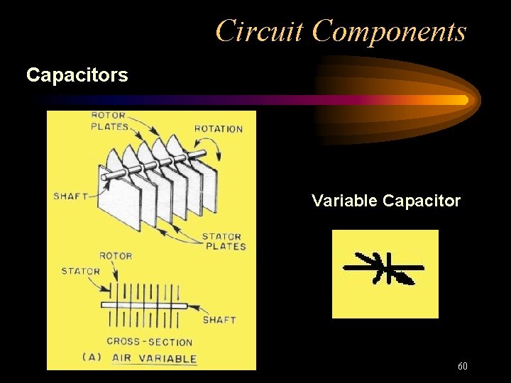
Circuit Components Capacitors Variable Capacitor 60
Practical Circuits Functional Layout Terms • Antenna switch • Feed line • Power supply • Antenna tuner • Dummy load 61
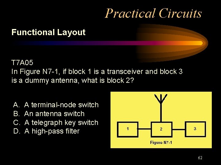
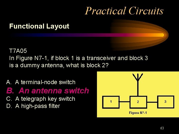
Practical Circuits Functional Layout T 7 A 05 In Figure N 7 -1, if block 1 is a transceiver and block 3 is a dummy antenna, what is block 2? A. B. C. D. A terminal-node switch An antenna switch A telegraph key switch A high-pass filter 62
Practical Circuits Functional Layout T 7 A 05 In Figure N 7 -1, if block 1 is a transceiver and block 3 is a dummy antenna, what is block 2? A. A terminal-node switch B. An antenna switch C. A telegraph key switch D. A high-pass filter 63
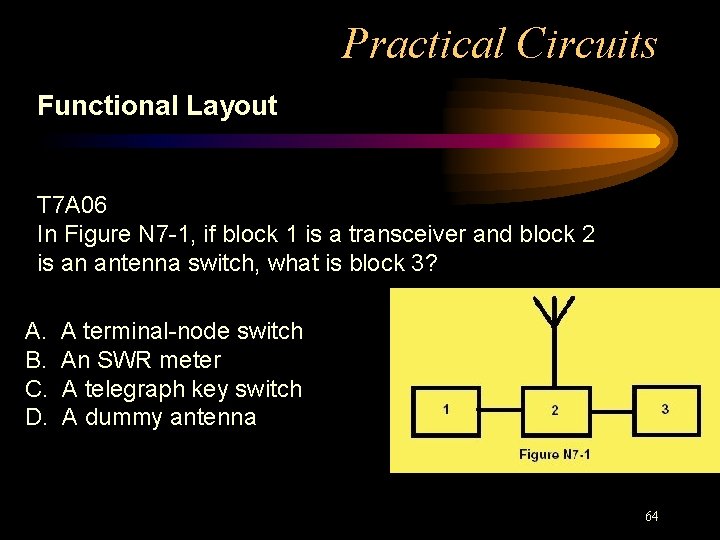
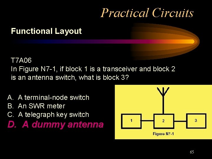
Practical Circuits Functional Layout T 7 A 06 In Figure N 7 -1, if block 1 is a transceiver and block 2 is an antenna switch, what is block 3? A. B. C. D. A terminal-node switch An SWR meter A telegraph key switch A dummy antenna 64
Practical Circuits Functional Layout T 7 A 06 In Figure N 7 -1, if block 1 is a transceiver and block 2 is an antenna switch, what is block 3? A. A terminal-node switch B. An SWR meter C. A telegraph key switch D. A dummy antenna 65
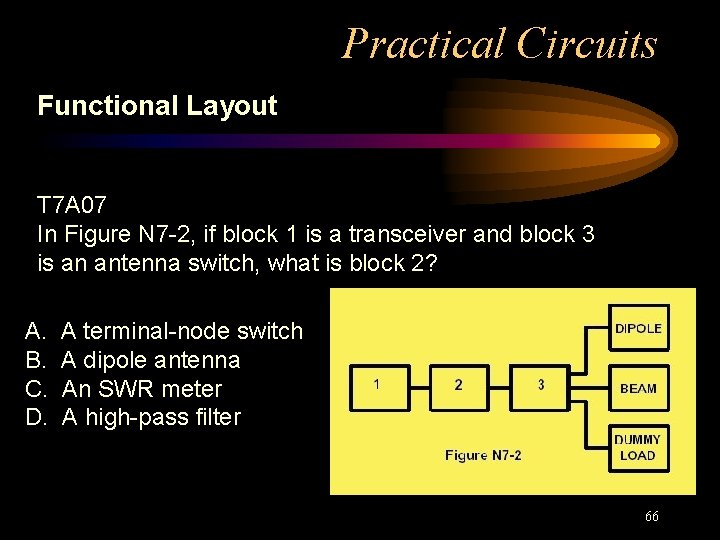
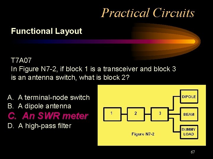
Practical Circuits Functional Layout T 7 A 07 In Figure N 7 -2, if block 1 is a transceiver and block 3 is an antenna switch, what is block 2? A. B. C. D. A terminal-node switch A dipole antenna An SWR meter A high-pass filter 66
Practical Circuits Functional Layout T 7 A 07 In Figure N 7 -2, if block 1 is a transceiver and block 3 is an antenna switch, what is block 2? A. A terminal-node switch B. A dipole antenna C. An SWR meter D. A high-pass filter 67
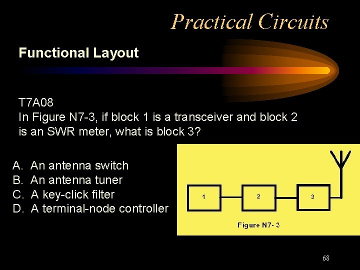
Practical Circuits Functional Layout T 7 A 08 In Figure N 7 -3, if block 1 is a transceiver and block 2 is an SWR meter, what is block 3? A. B. C. D. An antenna switch An antenna tuner A key-click filter A terminal-node controller 68
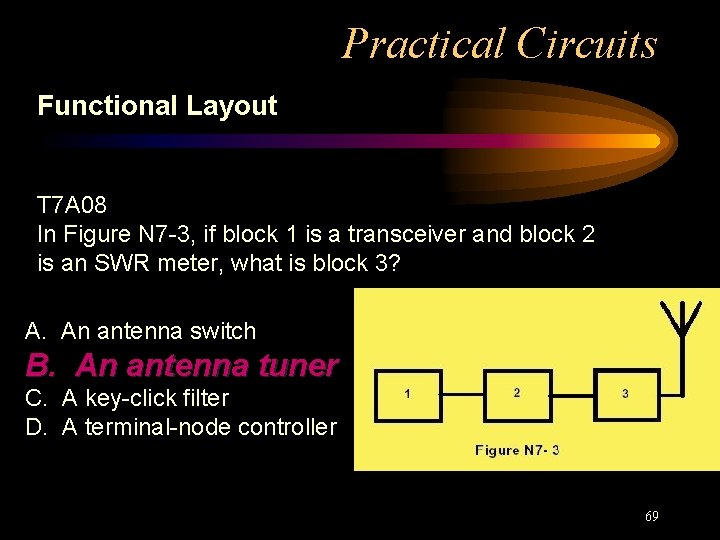
Practical Circuits Functional Layout T 7 A 08 In Figure N 7 -3, if block 1 is a transceiver and block 2 is an SWR meter, what is block 3? A. An antenna switch B. An antenna tuner C. A key-click filter D. A terminal-node controller 69
Practical Circuits Functional Layout • Microphone • Modem, teleprinter, computer • TNC Terminal Node Controller 70
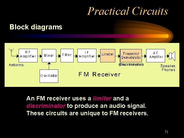
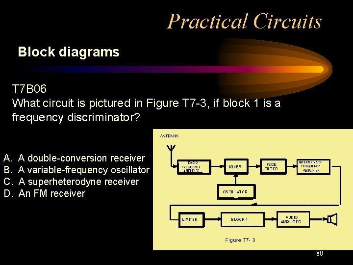
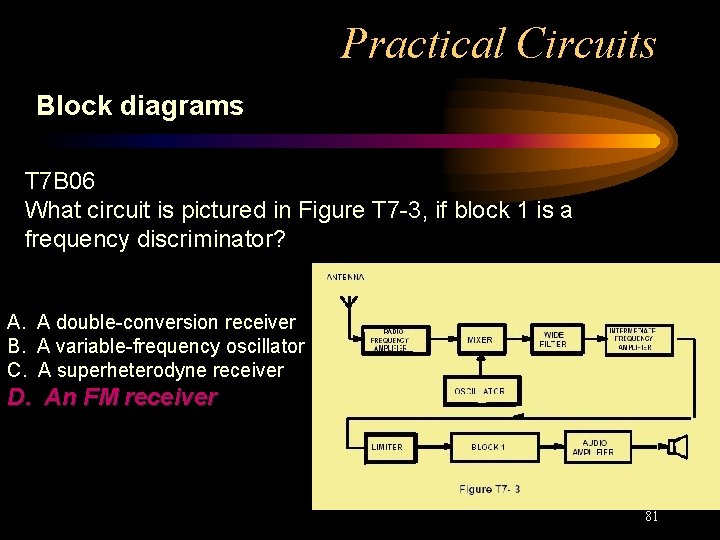
Practical Circuits Block diagrams An FM receiver uses a limiter and a discriminator to produce an audio signal. These circuits are unique to FM receivers. 71
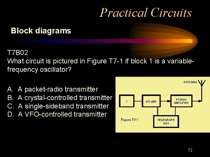
Practical Circuits Block diagrams T 7 B 02 What circuit is pictured in Figure T 7 -1 if block 1 is a variablefrequency oscillator? A. B. C. D. A packet-radio transmitter A crystal-controlled transmitter A single-sideband transmitter A VFO-controlled transmitter 72
Practical Circuits Block diagrams T 7 B 02 What circuit is pictured in Figure T 7 -1 if block 1 is a variablefrequency oscillator? A. A packet-radio transmitter B. A crystal-controlled transmitter C. A single-sideband transmitter D. A VFO-controlled transmitter 73
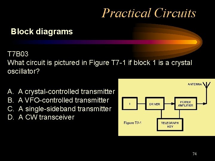
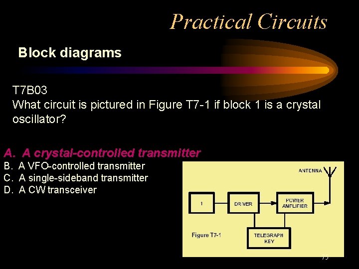
Practical Circuits Block diagrams T 7 B 03 What circuit is pictured in Figure T 7 -1 if block 1 is a crystal oscillator? A. B. C. D. A crystal-controlled transmitter A VFO-controlled transmitter A single-sideband transmitter A CW transceiver 74
Practical Circuits Block diagrams T 7 B 03 What circuit is pictured in Figure T 7 -1 if block 1 is a crystal oscillator? A. A crystal-controlled transmitter B. A VFO-controlled transmitter C. A single-sideband transmitter D. A CW transceiver 75
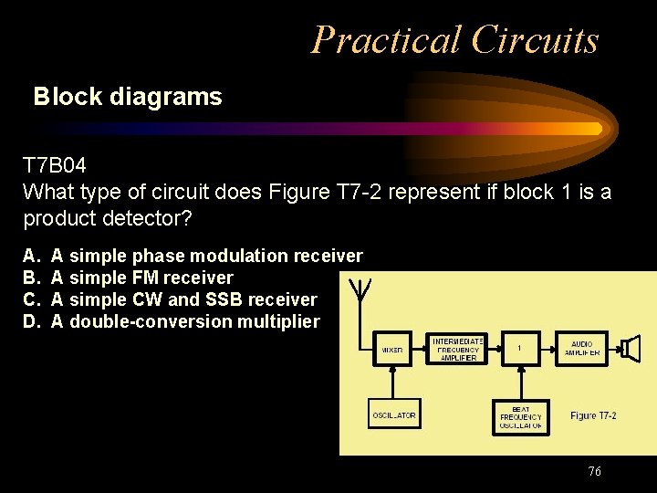
Practical Circuits Block diagrams T 7 B 04 What type of circuit does Figure T 7 -2 represent if block 1 is a product detector? A. B. C. D. A simple phase modulation receiver A simple FM receiver A simple CW and SSB receiver A double-conversion multiplier 76
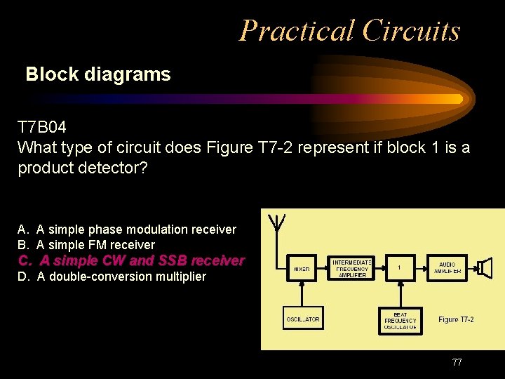
Practical Circuits Block diagrams T 7 B 04 What type of circuit does Figure T 7 -2 represent if block 1 is a product detector? A. A simple phase modulation receiver B. A simple FM receiver C. A simple CW and SSB receiver D. A double-conversion multiplier 77
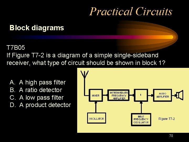
Practical Circuits Block diagrams T 7 B 05 If Figure T 7 -2 is a diagram of a simple single-sideband receiver, what type of circuit should be shown in block 1? A. B. C. D. A high pass filter A ratio detector A low pass filter A product detector 78
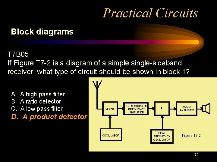
Practical Circuits Block diagrams T 7 B 05 If Figure T 7 -2 is a diagram of a simple single-sideband receiver, what type of circuit should be shown in block 1? A. A high pass filter B. A ratio detector C. A low pass filter D. A product detector 79
Practical Circuits Block diagrams T 7 B 06 What circuit is pictured in Figure T 7 -3, if block 1 is a frequency discriminator? A. B. C. D. A double-conversion receiver A variable-frequency oscillator A superheterodyne receiver An FM receiver 80
Practical Circuits Block diagrams T 7 B 06 What circuit is pictured in Figure T 7 -3, if block 1 is a frequency discriminator? A. A double-conversion receiver B. A variable-frequency oscillator C. A superheterodyne receiver D. An FM receiver 81
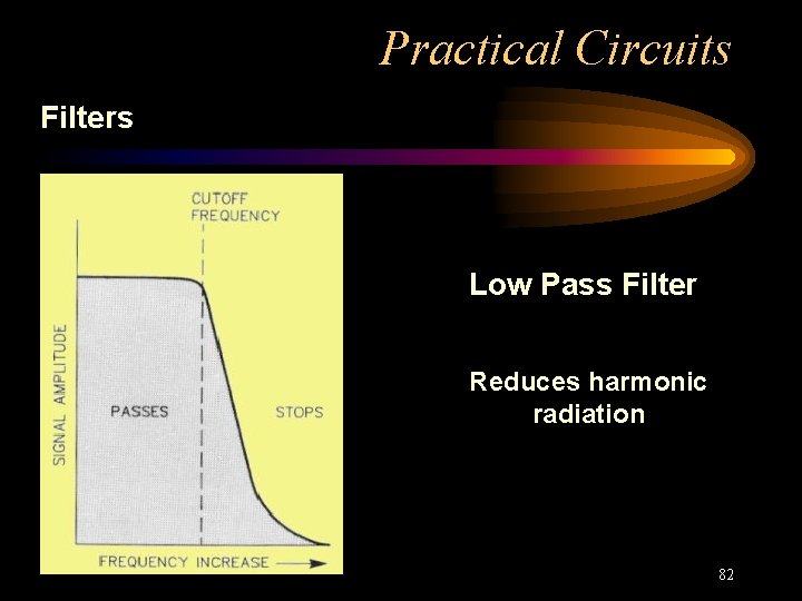
Practical Circuits Filters Low Pass Filter Reduces harmonic radiation 82
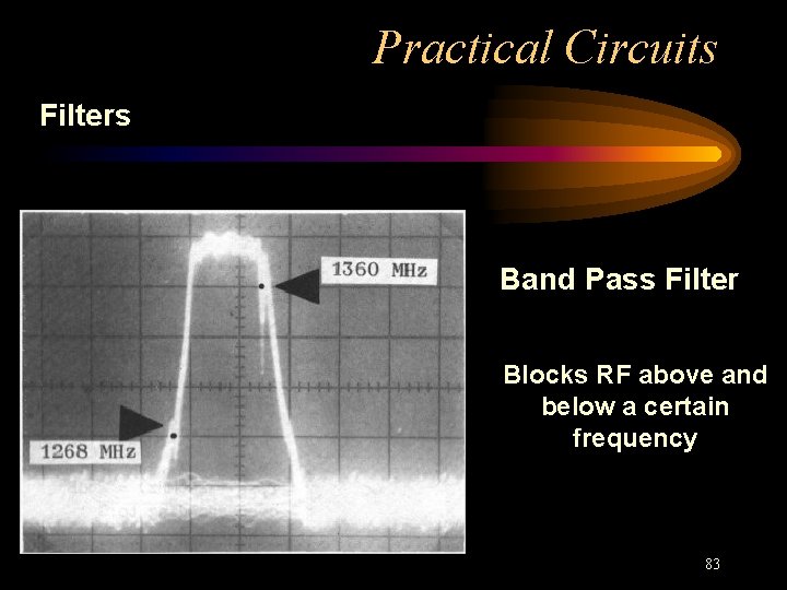
Practical Circuits Filters Band Pass Filter Blocks RF above and below a certain frequency 83
Practical Circuits A few more circuits • Detector • Duplexer 84
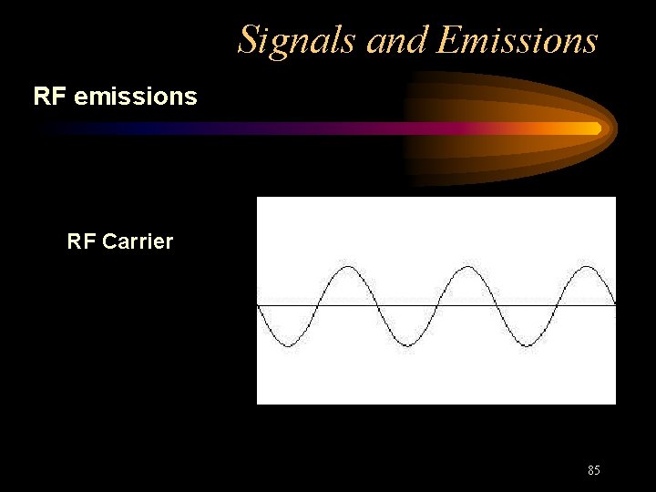
Signals and Emissions RF emissions RF Carrier 85
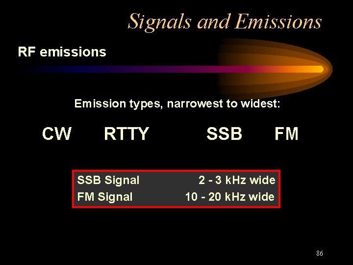
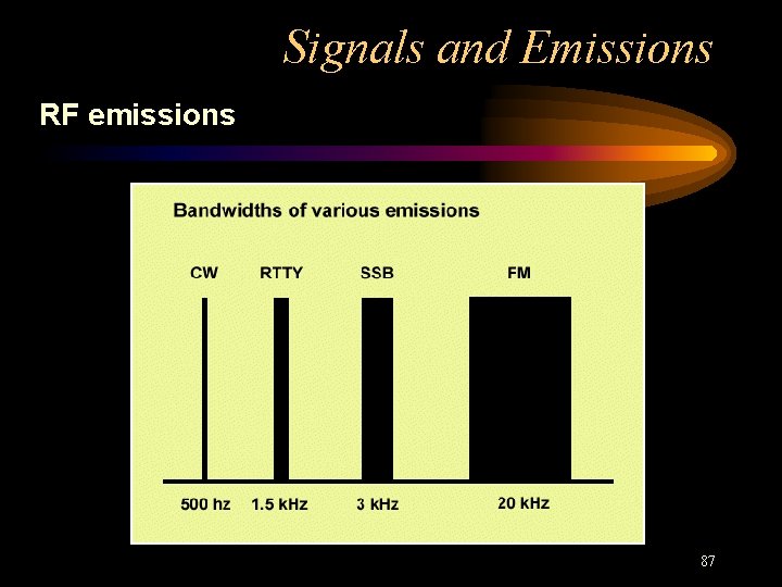
Signals and Emissions RF emissions Emission types, narrowest to widest: CW RTTY SSB Signal FM Signal SSB FM 2 - 3 k. Hz wide 10 - 20 k. Hz wide 86
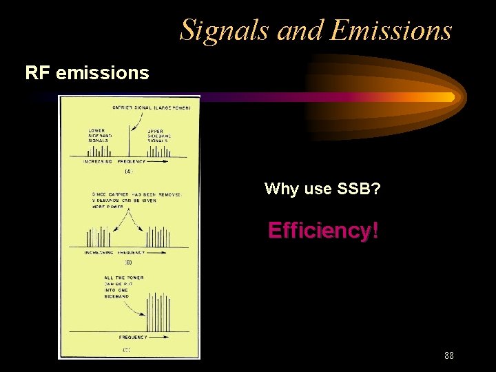
Signals and Emissions RF emissions 87
Signals and Emissions RF emissions Why use SSB? Efficiency! 88
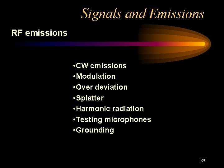
Signals and Emissions RF emissions • CW emissions • Modulation • Over deviation • Splatter • Harmonic radiation • Testing microphones • Grounding 89
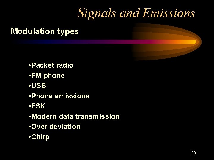
Signals and Emissions Modulation types • Packet radio • FM phone • USB • Phone emissions • FSK • Modern data transmission • Over deviation • Chirp 90
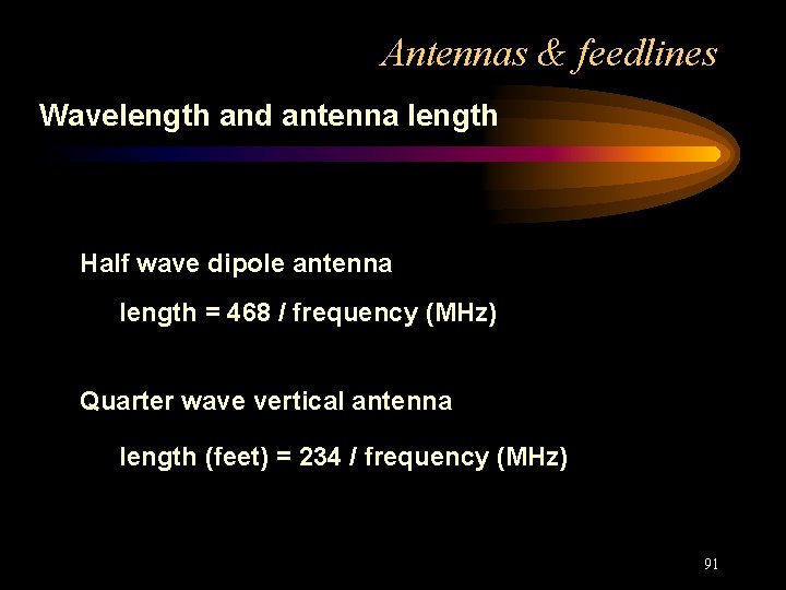
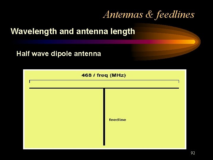
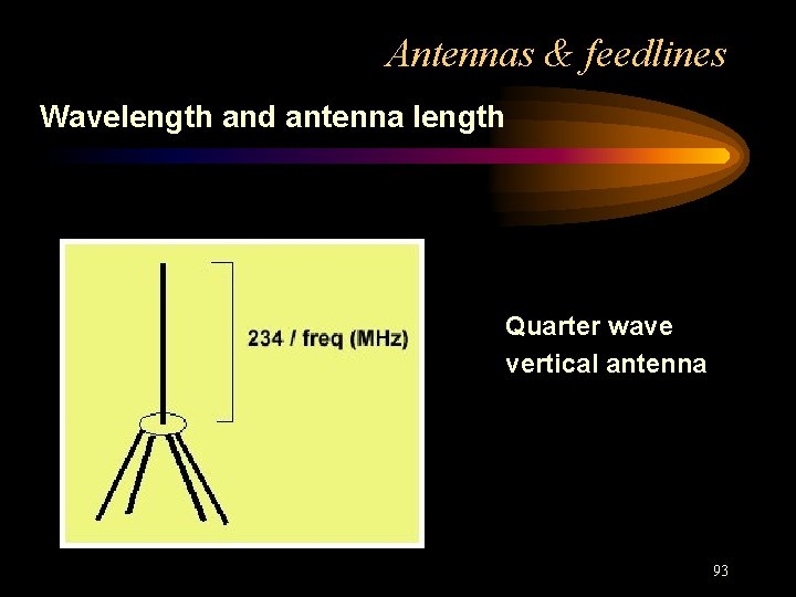
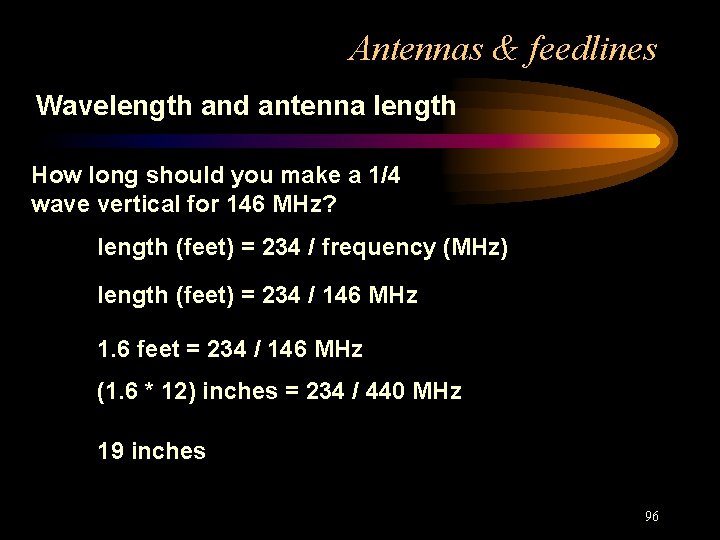
Antennas & feedlines Wavelength and antenna length Half wave dipole antenna length = 468 / frequency (MHz) Quarter wave vertical antenna length (feet) = 234 / frequency (MHz) 91
Antennas & feedlines Wavelength and antenna length Half wave dipole antenna 92
Antennas & feedlines Wavelength and antenna length Quarter wave vertical antenna 93
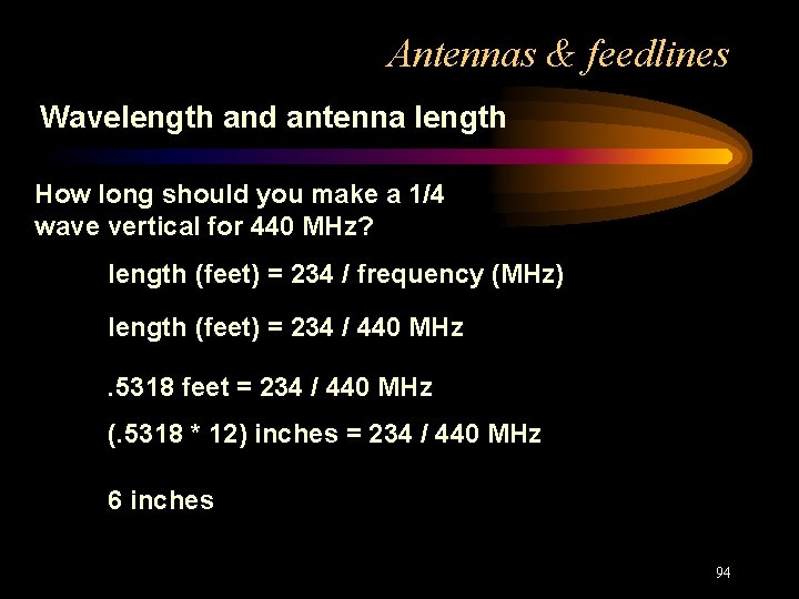
Antennas & feedlines Wavelength and antenna length How long should you make a 1/4 wave vertical for 440 MHz? length (feet) = 234 / frequency (MHz) length (feet) = 234 / 440 MHz. 5318 feet = 234 / 440 MHz (. 5318 * 12) inches = 234 / 440 MHz 6 inches 94
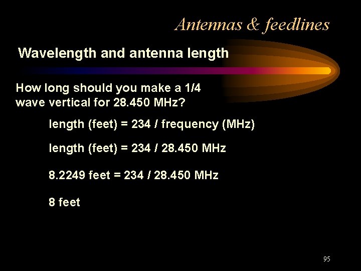
Antennas & feedlines Wavelength and antenna length How long should you make a 1/4 wave vertical for 28. 450 MHz? length (feet) = 234 / frequency (MHz) length (feet) = 234 / 28. 450 MHz 8. 2249 feet = 234 / 28. 450 MHz 8 feet 95
Antennas & feedlines Wavelength and antenna length How long should you make a 1/4 wave vertical for 146 MHz? length (feet) = 234 / frequency (MHz) length (feet) = 234 / 146 MHz 1. 6 feet = 234 / 146 MHz (1. 6 * 12) inches = 234 / 440 MHz 19 inches 96
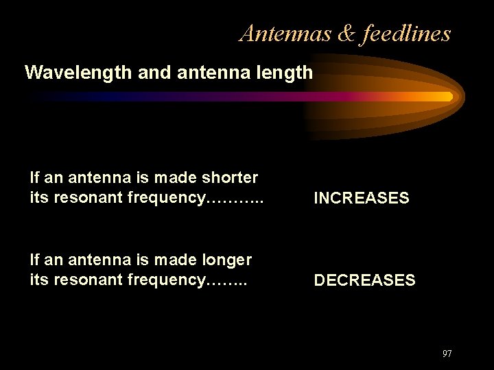
Antennas & feedlines Wavelength and antenna length If an antenna is made shorter its resonant frequency………. . INCREASES If an antenna is made longer its resonant frequency……. . DECREASES 97
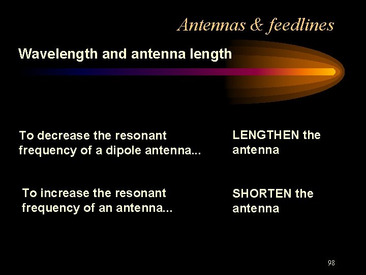
Antennas & feedlines Wavelength and antenna length To decrease the resonant frequency of a dipole antenna. . . LENGTHEN the antenna To increase the resonant frequency of an antenna. . . SHORTEN the antenna 98
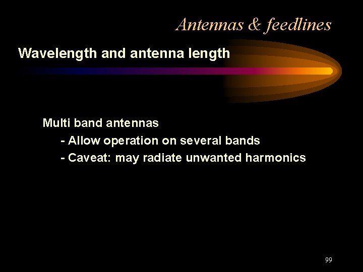
Antennas & feedlines Wavelength and antenna length Multi band antennas - Allow operation on several bands - Caveat: may radiate unwanted harmonics 99
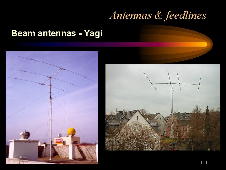
Antennas & feedlines Beam antennas - Yagi 100
Antennas & feedlines Beam antennas - Yagi 101
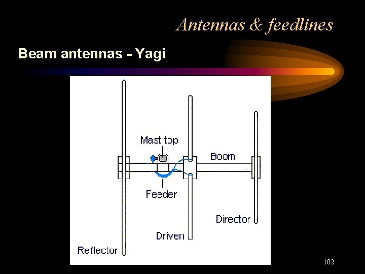
Antennas & feedlines Beam antennas - Yagi 102
Antennas & feedlines Beam antennas - Yagi • Directional antenna • Yagi construction • Driven element • Parasitic elements 103
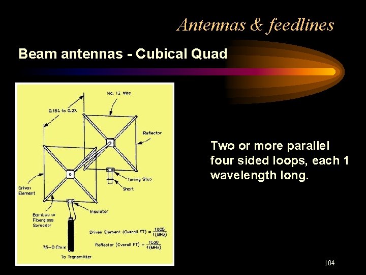
Antennas & feedlines Beam antennas - Cubical Quad Two or more parallel four sided loops, each 1 wavelength long. 104
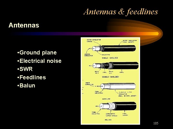
Antennas & feedlines Antennas • Ground plane • Electrical noise • SWR • Feedlines • Balun 105
RF Safety Fundamentals, terms • Use minimum power • Most hazardous frequencies • Biological effects • Power density • Near fields • Microwave hazards • FCC requirements • MPE and the human body • Specific absorption rate 106
RF Safety Rules & guidelines • Rules defined: FCC Part 1, OET Bulletin 65 • All sources of RF from a site must be considered • MPE average in uncontrolled area: 30 minutes • MPE average in controlled areas: 6 minutes • Portable devices • Certification of RF exposure rules: form 605 • All stations must comply • Licensee is responsible for compliance 107
RF Safety Rules & guidelines • Body’s ability to absorb RF • Duty cycle • Impact of duty cycle on minimum safe distance 108
RF Safety Routine station evaluation • Power density measurement vs. other methods • Do not have to perform calculations • Hand held antennas • UHF antennas • RF burns • Mobile installations • Amplifier shielding 109
Clubs and organizations • QST, Monthly magazine • New! Members-Only Web Access • Technical Information Service (TIS) • Ham Radio Equipment Insurance • A Voice in Washington • ARRL Field Organization An Amateur Radio VHF/UHF Wide Coverage Repeater Linking System Serving New Mexico, Southern Colorado, Western Oklahoma, West Texas and Eastern Arizona 110
Clubs and organizations Albuquerque Amateur Radio Club • License classes • Operating activities • Social gatherings • Public service 111