Chapter 26 Electromagnetism Click the mouse or press



- Slides: 147

Chapter 26: Electromagnetism Click the mouse or press the spacebar to continue.

Chapter 26 Electromagnetism In this chapter you will: ● Learn how combined electric and magnetic fields can be used to determine the masses of electrons, atoms, and molecules. ● Explain how electromagnetic waves are created, travel through space, and are detected.

Chapter 26 Table of Contents Chapter 26: Electromagnetism Section 26. 1: Interactions of Electric and Magnetic Fields and Matter Section 26. 2: Electric and Magnetic Fields in Space

Section 26. 1 Interactions of Electric and Magnetic Fields and Matter In this section you will: ● Describe the operation of a cathode-ray tube. ● Solve problems involving the interaction of charged particles with the electric and magnetic fields in cathode-ray tubes and mass spectrometers. ● Explain how a mass spectrometer separates ions of different masses.

Section 26. 1 Interactions of Electric and Magnetic Fields and Matter Mass of an Electron Although you may not know what the terms stand for, you have probably heard of shortwave radio, microwaves, and VHF and UHF television signals. Each of these terms is used to describe one of the many types of electromagnetic waves that are broadcast through the air to provide you with radio, television, and other forms of communication. All of these waves consist of electric and magnetic fields propagating through space.

Section 26. 1 Interactions of Electric and Magnetic Fields and Matter Mass of an Electron The key to understanding how these waves behave is understanding the nature of the electron. Why? Because electromagnetic waves are produced by accelerating electrons—the electrons’ charge produces electric fields and the electrons’ motion produces magnetic fields.

Section 26. 1 Interactions of Electric and Magnetic Fields and Matter Mass of an Electron Furthermore, the waves are broadcast and received by antennas, devices made of matter that also contain electrons. Thus, the logical first step in understanding how electromagnetic waves are produced, propagated, received, and used for so many devices is to learn about the properties of the electron.

Section 26. 1 Interactions of Electric and Magnetic Fields and Matter Mass of an Electron How do you determine the mass of something that cannot be seen with the unaided eye and whose mass is so small that it cannot be measured even by the most sensitive scale? Such was the challenge—that of determining the mass of an electron—facing physicists in the late 1800 s.

Section 26. 1 Interactions of Electric and Magnetic Fields and Matter Mass of an Electron The solution required a series of discoveries. The first piece of the puzzle came from Robert Millikan balanced charged oil droplets in an electric field and was able to determine the charge, q, of an electron (1. 602× 10− 19 C).

Section 26. 1 Interactions of Electric and Magnetic Fields and Matter Mass of an Electron Next, British physicist J. J. Thomson was able to determine the charge-to-mass ratio, q/m, of an electron. Knowing both the charge-to-mass ratio, q/m, and the charge of an electron, q, Thomson was able to calculate the mass of an electron.

Section 26. 1 Interactions of Electric and Magnetic Fields and Matter Thomson’s Experiments with Electrons Click image to view the movie.

Section 26. 1 Interactions of Electric and Magnetic Fields and Matter Thomson’s Experiments with Protons Thomson also used his cathode-ray test apparatus to determine the charge-to-mass ratio for positive ions. He took advantage of the fact that positively charged particles undergo the opposite deflection experienced by electrons moving through an electric or magnetic field.

Section 26. 1 Interactions of Electric and Magnetic Fields and Matter Thomson’s Experiments with Protons To accelerate positively charged particles into the deflection region, Thomson reversed the direction of the electric field between the cathode and anodes. He also added a small amount of hydrogen gas to the tube.

Section 26. 1 Interactions of Electric and Magnetic Fields and Matter Thomson’s Experiments with Protons The electric field pulled electrons off the hydrogen atoms, changing the atoms into positive ions. These positive hydrogen ions, or protons, were then accelerated through a tiny slit in the anode. The resulting proton beam passed through electric and magnetic fields on its way toward the end of the tube.

Section 26. 1 Interactions of Electric and Magnetic Fields and Matter Thomson’s Experiments with Protons Using this technique, the mass of a proton was determined in the same manner as was the mass of the electron. The mass of a proton was found to be 1. 67× 10− 27 kg. Thomson went on to use this technique to determine the masses of heavier ions produced when electrons were stripped from gases, such as helium, neon, and argon.

Section 26. 1 Interactions of Electric and Magnetic Fields and Matter Path Radius An electron with a mass of 9. 11× 10− 31 kg moves through a cathode-ray tube at 2. 0× 105 m/s perpendicular to a magnetic field of 3. 5× 10− 2 T. The electric field is turned off. What is the radius of the circular path that is followed by the electron?

Section 26. 1 Interactions of Electric and Magnetic Fields and Matter Path Radius Step 1: Analyze and Sketch the Problem

Section 26. 1 Interactions of Electric and Magnetic Fields and Matter Path Radius Draw the path of the electron and label the velocity, v. Sketch the magnetic field perpendicular to the velocity.

Section 26. 1 Interactions of Electric and Magnetic Fields and Matter Path Radius Diagram the force acting on the electron. Add the radius of the electron’s path to your sketch.

Section 26. 1 Interactions of Electric and Magnetic Fields and Matter Path Radius Identify the known and unknown variables. Known: Unknown: v = 2. 0× 105 m/s r=? B = 3. 5× 10− 2 T m = 9. 11× 10− 31 kg q = 1. 602× 10− 19 C

Section 26. 1 Interactions of Electric and Magnetic Fields and Matter Path Radius Step 2: Solve for the Unknown

Section 26. 1 Interactions of Electric and Magnetic Fields and Matter Path Radius Use Newton’s second law of motion to describe an electron in a cathode-ray tube subjected to a magnetic field.

Section 26. 1 Interactions of Electric and Magnetic Fields and Matter Path Radius Substitute m = 9. 11× 10− 31 kg, v = 2. 0× 105 m/s, B = 3. 5× 10− 2 T, q = 1. 602× 10− 19 C = 3. 3× 10− 5 m

Section 26. 1 Interactions of Electric and Magnetic Fields and Matter Path Radius Step 3: Evaluate the Answer

Section 26. 1 Interactions of Electric and Magnetic Fields and Matter Path Radius Are the units correct? The radius of the circular path is a length measurement, given in units of meters.

Section 26. 1 Interactions of Electric and Magnetic Fields and Matter Path Radius The steps covered were: Step 1: Analyze and Sketch the Problem Draw the path of the electron and label the velocity, v. Sketch the magnetic field perpendicular to the velocity. Diagram the force acting on the electron. Add the radius of the electron’s path to your sketch.

Section 26. 1 Interactions of Electric and Magnetic Fields and Matter Path Radius The steps covered were: Step 2: Solve for the Unknown Step 3: Evaluate the Answer

Section 26. 1 Interactions of Electric and Magnetic Fields and Matter The Mass Spectrometer Click image to view the movie.

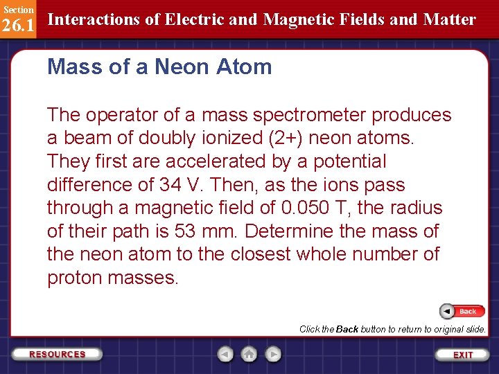
Section 26. 1 Interactions of Electric and Magnetic Fields and Matter Mass of a Neon Atom The operator of a mass spectrometer produces a beam of doubly ionized (2+) neon atoms. They are first accelerated by a potential difference of 34 V. Then, as the ions pass through a magnetic field of 0. 050 T, the radius of their path is 53 mm. Determine the mass of the neon atom to the closest whole number of proton masses.

Section 26. 1 Interactions of Electric and Magnetic Fields and Matter Mass of a Neon Atom Step 1: Analyze and Sketch the Problem

Section 26. 1 Interactions of Electric and Magnetic Fields and Matter Mass of a Neon Atom Draw the circular path of the ions. Label the radius. Draw and label the potential difference between the electrodes.

Section 26. 1 Interactions of Electric and Magnetic Fields and Matter Mass of a Neon Atom Identify the known and unknown variables. Known: Unknown: V = 34 V mneon = ? B = 0. 050 T Nproton = ? r = 0. 053 m mproton = 1. 67× 10– 27 kg q = 2(1. 60× 10− 19 C) = 3. 20× 10− 19 C

Section 26. 1 Interactions of Electric and Magnetic Fields and Matter Mass of a Neon Atom Step 2: Solve for the Unknown

Section 26. 1 Interactions of Electric and Magnetic Fields and Matter Mass of a Neon Atom Use the equation for the charge-to-mass ratio of an ion in a mass spectrometer.

Section 26. 1 Interactions of Electric and Magnetic Fields and Matter Mass of a Neon Atom Substitute q = 3. 2× 10− 19 C, B = 0. 050 T, r = 0. 053 m, and V = 34 V = 3. 3× 10− 26 kg

Section 26. 1 Interactions of Electric and Magnetic Fields and Matter Mass of a Neon Atom Divide the mass of neon by the mass of a proton to find the number of proton masses.

Section 26. 1 Interactions of Electric and Magnetic Fields and Matter Mass of a Neon Atom Step 3: Evaluate the Answer

Section 26. 1 Interactions of Electric and Magnetic Fields and Matter Mass of a Neon Atom Are the units correct? Mass should be measured in grams or kilograms. The number of protons should not be represented by any units. Is the magnitude realistic? Neon has two isotopes, with masses of approximately 20 and 22 proton masses.

Section 26. 1 Interactions of Electric and Magnetic Fields and Matter Mass of a Neon Atom The steps covered were: Step 1: Analyze and Sketch the Problem Draw the circular path of the ions. Label the radius. Draw and label the potential difference between the electrodes.

Section 26. 1 Interactions of Electric and Magnetic Fields and Matter Mass of a Neon Atom The steps covered were: Step 2: Solve for the Unknown Use the equation for the charge-to-mass ratio of an ion in a mass spectrometer. Divide the mass of neon by the mass of a proton to find the number of proton masses. Step 3: Evaluate the Answer

Section 26. 1 Interactions of Electric and Magnetic Fields and Matter Isotopic Analysis The approximate spacing between marks on the film for an ionized chromium (Cr) sample is shown in the figure.

Section 26. 1 Interactions of Electric and Magnetic Fields and Matter Isotopic Analysis The four distinct red marks indicate that a naturally occurring sample of chromium is composed of four isotopes. The width of the mark corresponds to the abundance of the isotope.

Section 26. 1 Interactions of Electric and Magnetic Fields and Matter Isotopic Analysis Note that the isotope with a mass number of 52 is the most abundant isotope, and that the sum of the percentages for the four isotopes equals 100 percent.

Section 26. 1 Interactions of Electric and Magnetic Fields and Matter Isotopic Analysis As you may recall from chemistry, the mass of each element listed in the periodic table is actually a weighted average of the masses of all of the stable isotopes of that element. Note that all of the chromium ions that hit the film have the same charge. Their charge depends on how many electrons were removed from the neutral chromium atoms used as the ion source. Recall that the ions are formed when accelerated electrons are used to knock electrons off neutral atoms.

Section 26. 1 Interactions of Electric and Magnetic Fields and Matter Isotopic Analysis After the first electron is removed, producing a singly ionized (1+) atom, more energy is required to remove the second electron and produce a double ionized (2+) atom. This additional energy can be provided by electrons that undergo a greater acceleration because they are subjected to a greater electric field. Thus, higher-energy accelerated electrons can produce both singly and doubly charged ions. In this way, the operator of the mass spectrometer can choose the charge on the ion to be studied.

Section 26. 1 Interactions of Electric and Magnetic Fields and Matter Other Applications Mass spectrometers have numerous applications. Rather than striking a detector to measure relative abundance, the separated isotopes are collected. The different isotopes are, in turn, used in varying applications.

Section 26. 1 Interactions of Electric and Magnetic Fields and Matter Other Applications Mass spectrometers are also used to detect and identify trace amounts of molecules in a sample, an application extensively used in the environmental and forensic sciences. The device is so sensitive that researchers are able to separate ions with mass differences as small as one ten-thousandth of one percent and are able to identify the presence of a single molecule within a 10 billion-molecule sample.

Section 26. 1 Section Check Question 1 In Thomson’s cathode-ray tube experiment, the velocities of the electrons are such that the beam of electrons follows a straight or undeflected path. Which of the following conditions is satisfied? A. C. B. D.

Section 26. 1 Section Check Answer 1 Reason: In Thomson’s cathode-ray tube experiment, the electric field, which was produced by charged parallel plates, was oriented perpendicular to the beam. The electric field (of strength E) produced a force equal to q. E that acted on the electrons and deflected them upward, toward the positive plate. A magnetic field (of strength B) produced a force (equal to Bqv, where v is the electron velocity) that acted on the electrons and deflected them downward.

Section 26. 1 Section Check Answer 1 Reason: The electric and magnetic fields could be adjusted until the beam of electrons followed a straight, or undeflected, path. When this occured, the forces due to the two fields were equal in magnitude and opposite in direction. Mathematically, this can be represented as Bqv = Eq.

Section 26. 1 Section Check Question 2 In Thomson’s cathode-ray tube experiment, if the electric field is turned off and only the force due to the magnetic field remains, which of the following conditions is satisfied? A. C. B. D.

Section 26. 1 Section Check Answer 2 Reason: In Thomson’s cathode-ray tube experiment, if the electric field is turned off, only the force due to the magnetic field remains. The magnetic force is perpendicular to the direction of motion of the electrons, causing them to undergo centripetal (center-directed) acceleration. The accelerating electrons follow a circular path of radius, r.

Section 26. 1 Section Check Answer 2 Reason: Using Newton’s second law of motion, the following equation can be written to describe the electron’s path:

Section 26. 1 Section Check Question 3 What is a mass spectrometer? How are positive ions formed in a mass spectrometer?

Section 26. 1 Section Check Answer 3 A mass spectrometer is a device similar to Thomson’s cathode-ray tube that is commonly used to study isotopes. The mass spectrometer is able to precisely measure the charge-to-mass ratios of positive ions. From the charge-to-mass ratio, the mass of each isotope can be calculated. The material under investigation is called the ion source, as it is used to produce the positive ions.

Section 26. 1 Section Check Answer 3 The ion source must either be a gas or a material that can be heated to form a vapor. The positive ions are formed when accelerated electrons strike the gas or vapor atoms. The collisions knock electrons off the atoms, forming positive ions.

Section 26. 1 Section Check Question 4 The operator of a mass spectrometer produces a beam of singly ionized (1+) oxygen atoms. They are first accelerated by a potential difference of 110 V. Then, as the ions pass through a magnetic field of 7. 2× 10 2 T, the radius of their path is 0. 085 m. Find the mass of an oxygen atom. (Given q = 1. 6× 10 19 C).

Section 26. 1 Section Check Question 4 A. B. C. D.

Section 26. 1 Section Check Answer 4 Reason: Charge to mass ratio of an ion in a mass spectrometer is given by:

Section 26. 1 Section Check Answer 4 Reason: In a mass spectrometer, the ratio of an ion’s charge to its mass is equal to the ratio of twice the potential difference divided by the product of the square of the magnetic field strength and the square of the radius of the ion’s circular path.

Section 26. 1 Section Check

Section 26. 2 Electric and Magnetic Fields in Space In this section you will: ● Describe how electromagnetic waves propagate through space. ● Solve problems involving electromagnetic wave properties. ● Describe the factors affecting an antenna’s ability to receive an electromagnetic wave of a specific wavelength. ● Solve problems involving electromagnetic wave propagation through dielectrics.

Section 26. 2 Electric and Magnetic Fields in Space Electromagnetic Waves Although you probably do not realize it, you rely on electromagnetic waves every day. Signals broadcast from television and radio stations, orbiting satellites, and even those emanating from distant galaxies are all electromagnetic waves. In this section, you will learn about the fields that make up electromagnetic waves, and how the waves are produced and received.

Section 26. 2 Electric and Magnetic Fields in Space Electromagnetic Waves Great advancements in the understanding of electromagnetic waves were made during the nineteenth century. These advancements led to the development of new devices and technologies that had a huge impact on modern society.

Section 26. 2 Electric and Magnetic Fields in Space A Series of Breakthroughs In 1821, while performing a demonstration for his students, Danish physicist Hans Christian Oersted noticed that an electric current caused the needle in a nearby compass to deflect. Oersted realized that his observation displayed a fundamental connection between electricity and magnetism.

Section 26. 2 Electric and Magnetic Fields in Space A Series of Breakthroughs He concluded that an electric current in a conductor produces a magnetic field, and that a changing electric current produces a changing magnetic field. Oersted’s discovery created excitement in the scientific community and led to a flood of new research.

Section 26. 2 Electric and Magnetic Fields in Space A Series of Breakthroughs Eleven years after Oersted's discovery, Englishman Michael Faraday and American high school physics teacher John Henry independently discovered induction. Induction is the production of an electric field due to a moving magnetic field.

Section 26. 2 Electric and Magnetic Fields in Space A Series of Breakthroughs Interestingly, induced electric fields exist even if there is not a wire present, as shown in the animation. Thus, a changing magnetic field produces a corresponding changing electric field.

Section 26. 2 Electric and Magnetic Fields in Space A Series of Breakthroughs Notice that the field lines of the induced electric field are closed loops. This is because, unlike an electrostatic field, there are no charges on which the field lines begin or end.

Section 26. 2 Electric and Magnetic Fields in Space A Series of Breakthroughs In 1860, Scottish physicist James Maxwell postulated that the opposite of induction is also true; that is, a changing electric field produces a changing magnetic field. This is shown in the animation.

Section 26. 2 Electric and Magnetic Fields in Space A Series of Breakthroughs Maxwell also suggested that charges were not necessary—a changing electric field alone would produce the magnetic field. He then predicted that both accelerating charges and changing magnetic fields would produce electric and magnetic fields that move through space.

Section 26. 2 Electric and Magnetic Fields in Space A Series of Breakthroughs A combined electric and magnetic field that travels through space is an electromagnetic wave, or EM wave. The orientations of the fields making up an electromagnetic wave are shown in the figure.

Section 26. 2 Electric and Magnetic Fields in Space A Series of Breakthroughs In 1887, Heinrich Hertz, a German physicist, experimentally confirmed that Maxwell’s theory was correct. Maxwell’s theory led to a complete description of electricity and magnetism.

Section 26. 2 Electric and Magnetic Fields in Space Electromagnetic Wave Properties The speed of an electromagnetic wave was later found to be approximately 3. 00× 108 m/s, now denoted as c, the speed of light. Light, a type of electromagnetic wave, and all other forms of electromagnetic waves, travel through space at c.

Section 26. 2 Electric and Magnetic Fields in Space Electromagnetic Wave Properties The wavelength of an electromagnetic wave, its frequency, and the speed of light all are related.

Section 26. 2 Electric and Magnetic Fields in Space Electromagnetic Wave Properties Wavelength-Frequency Relationship for a Wave The wavelength of a wave is equal to its speed divided by its frequency. In this equation, the wavelength, λ, is measured in m; the speed, v, is measured in m/s; and the frequency, f, is measured in Hz.

Section 26. 2 Electric and Magnetic Fields in Space Electromagnetic Wave Properties Note that for an electromagnetic wave traveling in air or a vacuum, the speed, v, is equal to c, the speed of light. Thus, for an electromagnetic wave, the equation becomes the following: In the equation, c = 3. 00× 108 m/s.

Section 26. 2 Electric and Magnetic Fields in Space Electromagnetic Wave Properties Note that in the wavelength-frequency equation, the product of frequency and wavelength is constant—equal to c—for any electromagnetic wave. Thus, as wavelength increases, frequency decreases, and vice versa. In other words, an electromagnetic wave with a long wavelength has a low frequency, whereas an electromagnetic wave with a short wavelength has a high frequency.

Section 26. 2 Electric and Magnetic Fields in Space Electromagnetic Wave Propagation Through Matter Electromagnetic waves also can travel through matter. Sunlight shining through a glass of water is an example of light waves traveling through three different forms of matter: air, glass, and water. Air, glass, and water are nonconducting materials known as dielectrics.

Section 26. 2 Electric and Magnetic Fields in Space Electromagnetic Wave Propagation Through Matter The velocity of an electromagnetic wave through a dielectric is always less than the speed of the wave in a vacuum, and it can be calculated using the following equation:

Section 26. 2 Electric and Magnetic Fields in Space Electromagnetic Wave Propagation Through Matter In this equation, the wave velocity, v, is measured in m/s; the speed of light, c, has a value of 3. 00× 108 m/s; and the relative dielectric constant, K, is a dimensionless quantity. In a vacuum, K = 1. 00000, and the wave velocity is equal to c. In air, K = 1. 00054, and electromagnetic waves move just slightly slower than c.

Section 26. 2 Electric and Magnetic Fields in Space Electromagnetic Wave Propagation Through Space The formation of an electromagnetic wave is shown in the figure.

Section 26. 2 Electric and Magnetic Fields in Space Electromagnetic Wave Propagation Through Space An antenna, which is a wire designed to transmit or receive electromagnetic waves, is connected to an alternating current (AC) source. The AC source produces a varying potential difference in the antenna that alternates at the frequency of the AC source. This varying potential difference generates a corresponding varying electric field that propagates away from the antenna.

Section 26. 2 Electric and Magnetic Fields in Space Electromagnetic Wave Propagation Through Space The changing electric field also generates a varying magnetic field perpendicular to the page. Although the magnetic field is not shown in the figure, it also propagates away from the antenna.

Section 26. 2 Electric and Magnetic Fields in Space Electromagnetic Wave Propagation Through Space The combined electric and magnetic fields are electromagnetic waves that spread out into space, moving at the speed of light.

Section 26. 2 Electric and Magnetic Fields in Space Electromagnetic Wave Propagation Through Space If it were possible to see invisible electromagnetic waves approaching, the changing fields would appear as in the figure.

Section 26. 2 Electric and Magnetic Fields in Space Electromagnetic Wave Propagation Through Space The electric field oscillates up and down, while the magnetic field oscillates at right angles to the electric field. Both of the fields are at right angles to the wave direction. Note that an electromagnetic wave produced by an antenna is polarized; that is, its electric field is parallel to the antenna’s conductor.

Section 26. 2 Electric and Magnetic Fields in Space Waves from an AC Source As you just learned, an AC source connected to an antenna can transmit electromagnetic waves. The wave frequency is equal to the frequency of the rotating AC generator and is limited to about 1 k. Hz. The range of frequencies and wavelengths that make up all forms of electromagnetic radiation is shown in the figure on the next slide and is called the electromagnetic spectrum.

Section 26. 2 Electric and Magnetic Fields in Space Waves from an AC Source

Section 26. 2 Electric and Magnetic Fields in Space Waves from a Coil and a Capacitor A common method of generating high-frequency electromagnetic waves is to use a coil and a capacitor connected in a series circuit. If the capacitor is charged by a battery, the potential difference across the capacitor creates an electric field. When the battery is removed, the capacitor discharges as the stored electrons flow through the coil, creating a magnetic field.

Section 26. 2 Electric and Magnetic Fields in Space Waves from a Coil and a Capacitor When the capacitor is discharged, the coil’s magnetic field collapses. A back-EMF then develops and recharges the capacitor in the opposite direction, and the process is repeated. When an antenna is connected across the capacitor, the fields of the capacitor are transmitted into space.

Section 26. 2 Electric and Magnetic Fields in Space Waves from a Coil and a Capacitor One complete oscillation cycle is shown in the animation.

Section 26. 2 Electric and Magnetic Fields in Space Waves from a Coil and a Capacitor The process occurring in the coil-and-capacitor circuit can be compared with the cyclic oscillations of a swinging pendulum, as shown in the figure.

Section 26. 2 Electric and Magnetic Fields in Space Waves from a Coil and a Capacitor Assume that the electrons in the coil and the capacitor are represented by the pendulum’s bob. The moving bob has the greatest speed at the bottom of its swing, a position at which kinetic energy, KE, is maximized, and potential energy, PE, due to gravity is zero. This point in the pendulum’s motion, shown in the animation on the next slide, is similar to the peak electric current flow in the coil when the charge on the capacitor is zero.

Section 26. 2 Electric and Magnetic Fields in Space Waves from a Coil and a Capacitor

Section 26. 2 Electric and Magnetic Fields in Space Waves from a Coil and a Capacitor When the bob reaches the peak of its swing, its vertical displacement and PE are maximized, whereas its KE is zero because the bob’s velocity is zero. This point in the motion is similar to when the capacitor, as shown in the animation on the next slide, holds the maximum charge and the current through the coil is zero.

Section 26. 2 Electric and Magnetic Fields in Space Waves from a Coil and a Capacitor

Section 26. 2 Electric and Magnetic Fields in Space Energy in the Coil-and-Capacitor Circuit As you just learned, the PE of the pendulum is largest when its vertical displacement is greatest, and the KE is largest when the velocity is greatest. The sum of the PE and KE—the total energy—is constant throughout the motion of the pendulum. In the coil-and-capacitor circuit, both the magnetic field produced by the coil and the electric field in the capacitor contain energy.

Section 26. 2 Electric and Magnetic Fields in Space Energy in the Coil-and-Capacitor Circuit When the current is largest, the energy stored in the magnetic field is greatest. When the current is zero, the electric field of the capacitor is largest, and all the energy is contained in the electric field.

Section 26. 2 Electric and Magnetic Fields in Space Energy in the Coil-and-Capacitor Circuit The total energy of the circuit (the sum of the magnetic field energy, the electric field energy, thermal losses, and the energy carried away by the generated electromagnetic waves) is constant. Energy that is carried, or radiated, in the form of electromagnetic waves is frequently called electromagnetic radiation.

Section 26. 2 Electric and Magnetic Fields in Space Energy in the Coil-and-Capacitor Circuit Just as a pendulum eventually stops swinging if it is left alone, the oscillations in a coil and capacitor die out over time due to resistance in the circuit. The oscillations of both systems can be made to continue by adding energy.

Section 26. 2 Electric and Magnetic Fields in Space Energy in the Coil-and-Capacitor Circuit Gentle pushes, applied at the correct times, will keep a pendulum swinging. The largest amplitude swings occur when the frequency of pushes matches the frequency of swinging motion. This is the condition of resonance, which was discussed in Chapter 14.

Section 26. 2 Electric and Magnetic Fields in Space Energy in the Coil-and-Capacitor Circuit Similarly, voltage pulses applied to the coil-andcapacitor circuit at the right frequency keep the oscillations in the circuit going.

Section 26. 2 Electric and Magnetic Fields in Space Energy in the Coil-and-Capacitor Circuit One way of doing this is to add a second coil to the circuit, to form a transformer. A transformer is shown in the figure.

Section 26. 2 Electric and Magnetic Fields in Space Energy in the Coil-and-Capacitor Circuit The alternating current induced in the secondary coil is increased by an amplifier and added back to the coil and capacitor. This type of circuit can produce frequencies up to approximately 400 MHz.

Section 26. 2 Electric and Magnetic Fields in Space Waves from a Resonant Cavity The oscillation frequency produced by a coil-andcapacitor circuit can be increased by decreasing the size of the coil and the capacitor used. However, above frequencies of 1 GHz, individual coils and capacitors can no longer be used.

Section 26. 2 Electric and Magnetic Fields in Space Waves from a Resonant Cavity High frequency microwaves, with frequencies from 1 GHz to 100 GHz, are produced using a resonant cavity. The resonant cavity is a rectangular box that acts as both a coil and a capacitor. The size of the box determines the frequency of oscillation. Microwave ovens have resonant cavities that produce the microwaves used to cook food.

Section 26. 2 Electric and Magnetic Fields in Space Waves from a Resonant Cavity To produce even higher frequency infrared waves, the size of the resonant cavity would have to be reduced to molecular size. The oscillating electrons that produce infrared waves are, in fact, within the molecules.

Section 26. 2 Electric and Magnetic Fields in Space Waves from a Resonant Cavity Visible and ultraviolet waves are generated by electrons within atoms. X-rays and gamma rays are the result of accelerating charges in the nuclei of atoms. All electromagnetic waves arise from accelerated charges, and all travel at the speed of light.

Section 26. 2 Electric and Magnetic Fields in Space Waves from Piezoelectricity Coils and capacitors are not the only method of generating oscillation voltages. Quartz crystals deform when a voltage is applied across them, a property known as piezoelectricity. The application of an AC voltage to a cut section of quartz crystal results in sustained oscillations. An inverse linear relationship exists between crystal thickness and oscillation frequency.

Section 26. 2 Electric and Magnetic Fields in Space Waves from Piezoelectricity Just as a piece of metal vibrates at a specific frequency when it is bent and released, so does a quartz crystal. A crystal can be cut so that it vibrates at a specific desired frequency. An applied voltage deforms the crystal and starts the vibrations.

Section 26. 2 Electric and Magnetic Fields in Space Waves from Piezoelectricity The piezoelectric property also generates an EMF when the crystal is deformed. Because this EMF is produced at the vibrating frequency of the crystal, it can be amplified and returned to the crystal to keep it vibrating. Because of their nearly constant frequencies of vibration, quartz crystals are commonly used in watches.

Section 26. 2 Electric and Magnetic Fields in Space Reception of Electromagnetic Waves Now that you know how electromagnetic waves are produced and transmitted, how do you suppose the waves are detected? As you may have guessed, reception involves an antenna.

Section 26. 2 Electric and Magnetic Fields in Space Reception of Electromagnetic Waves As shown in the figure, the wave’s electric fields accelerate the electrons of the material making up the antenna.

Section 26. 2 Electric and Magnetic Fields in Space Reception of Electromagnetic Waves The acceleration is largest when the antenna is positioned in the same direction as the wave polarization; that is, when it is parallel to the direction of the wave’s electric fields. A potential difference across the terminals of the antenna oscillates at the frequency of the electromagnetic wave.

Section 26. 2 Electric and Magnetic Fields in Space Reception of Electromagnetic Waves This voltage is largest when the length of the antenna is one-half the wavelength of the wave it is to detect. Thus, an antenna’s length is designed to be one-half of the wavelength of the wave it is supposed to receive. For this reason, an antenna designed to receive radio and television waves is much longer than one designed to receive microwaves.

Section 26. 2 Electric and Magnetic Fields in Space Reception of Electromagnetic Waves While a simple wire antenna can detect electromagnetic waves, several wires are more effective. A television antenna often consists of two or more wires spaced about one-quarter wavelength apart. Electric fields that are generated in the individual wires form constructive interference patterns that increase the strength of the signal.

Section 26. 2 Electric and Magnetic Fields in Space Reception of Electromagnetic Waves It is important to realize that all electromagnetic waves, not just visible light waves, undergo reflection, refraction, and diffraction. Thus, it should not be a surprise to learn that dish antennas, like the one shown at the beginning of this chapter, reflect very short wavelength electromagnetic signals, just as parabolic mirrors reflect visible light waves. A dish antenna’s large surface area for collecting and focusing waves makes it well-suited to receive weak radio signals.

Section 26. 2 Electric and Magnetic Fields in Space Reception of Electromagnetic Waves A parabolic dish antenna works by reflecting and focusing the received signals off its surface and into a device called the horn. The horn, which is supported by a tripod structure over the main dish, contains a short dipole antenna. The horn channels the signals to a receiver, a device consisting of an antenna, a coil-and-capacitor circuit, a detector to decode the signal, and an amplifier.

Section 26. 2 Electric and Magnetic Fields in Space Selection of Waves As you know, many different radio and television stations transmit electromagnetic waves at the same time. If the information being broadcast is to be understood, the waves of a particular station must be selected. To select waves of a particular frequency (and reject the others) a tuner uses a coil-and-capacitor circuit connected to an antenna.

Section 26. 2 Electric and Magnetic Fields in Space Selection of Waves The capacitance is adjusted until the oscillation frequency of the circuit equals the frequency of the desired wave. When this is done, only waves of the desired frequency can cause significant oscillations of the electrons in the circuit.

Section 26. 2 Electric and Magnetic Fields in Space Energy from Waves carry energy as well as information. At microwave and infrared frequencies, waves accelerate electrons in molecules. The energy of the waves is converted to thermal energy in the molecules. This is how microwave ovens cook food.

Section 26. 2 Electric and Magnetic Fields in Space Energy from Waves Light waves can also transfer energy to electrons. Photographic film makes use of this fact by using the energy in light waves to drive a chemical reaction within the film. The result is a permanent record of the light from the subject that strikes the film. At higher frequencies, ultraviolet (UV) radiation causes many chemical reactions to occur, including those in living cells that produce sunburn and tanning.

Section 26. 2 Electric and Magnetic Fields in Space X-Rays In 1895, German physicist Wilhelm Roentgen sent electrons through an evacuated glass tube, similar to the one shown in the figure. Roentgen used a very high voltage across the tube to give the electrons large kinetic energies. -

Section 26. 2 Electric and Magnetic Fields in Space X-Rays When the electrons struck the metal anode target within the tube, Roentgen noticed a glow on a phosphorescent screen a short distance away. The glow continued even when a piece of wood was placed between the tube and the screen. He concluded that some kind of highly penetrating rays were coming from the tube.

Section 26. 2 Electric and Magnetic Fields in Space X-Rays Because Roentgen did not know what these strange rays were, he called them X-rays. A few weeks later, Roentgen found that photographic plates were darkened by X-rays. He also discovered that soft body tissue was transparent to the rays, but that bone blocked them. He produced an X-ray picture of his wife’s hand. Within months, doctors recognized the valuable medical uses of this phenomenon.

Section 26. 2 Electric and Magnetic Fields in Space X-Rays It now is known that an X-ray is a high-frequency electromagnetic wave. In an X-ray tube, electrons first are accelerated to high speeds by means of potential differences of 20, 000 V or more. When the electrons crash into matter, their kinetic energies are converted into the very highfrequency electromagnetic waves called X-rays.

Section 26. 2 Electric and Magnetic Fields in Space X-Rays Electrons are accelerated to these speeds in cathode-ray tubes, such as the picture tube in a television. When the electrons hit the inside surface of a television screen’s face plate, they come to a sudden stop and cause the colored phosphors to glow. This sudden stopping of the electrons also can produce harmful X-rays. Thus, the face-plate glass in a television screen contains lead to stop the X-rays and protect the viewers.

Section 26. 2 Section Check Question 1 Which of the following statements about the production of electric and magnetic fields is true?

Section 26. 2 Section Check Question 1 A. Only a changing electric field can produce a changing magnetic field, but a changing magnetic field cannot produce a changing electric field. B. Only a changing magnetic field can produce a changing electric field, but a changing electric field cannot produce a changing magnetic field.

Section 26. 2 Section Check Question 1 C. A changing electric field can produce a changing magnetic field, and a changing magnetic field can produce a changing electric field. D. A changing electric field cannot produce a changing magnetic field. A changing magnetic field cannot produce a changing electric field.

Section 26. 2 Section Check Answer 1 C. A changing electric field can produce a changing magnetic field, and a changing magnetic field can produce a changing electric field.

Section 26. 2 Section Check Answer 1 Reason: Michael Faraday and John Henry independently discovered induction. Induction is the production of an electric field due to a moving magnetic field. Interestingly, induced electric fields exist even if no wire is present. Thus a changing magnetic field produces a corresponding changing electric field.

Section 26. 2 Section Check Answer 1 Reason: Later on, in 1860, James Maxwell postulated that the opposite of induction is also true; that is, a changing electric field produces a changing magnetic field.

Section 26. 2 Section Check Question 2 What is the speed of an electromagnetic wave with a wavelength of 1. 5 × 10 5 m that is traveling through a vacuum? A. C. B. D.

Section 26. 2 Section Check Answer 2 Reason: The wavelength-frequency relationship for an electromagnetic wave is:

Section 26. 2 Section Check Answer 2 Reason: Note that in the wavelength-frequency equation, the product of wavelength (λ) and frequency (f) is constant—equal to c—for any electromagnetic wave traveling through a vacuum. Thus, if the wavelength increases, the frequency decreases and vice versa. That is, whatever the frequency or wavelength, the speed of an electromagnetic wave through a vacuum is always 3. 0 × 108 m/s.

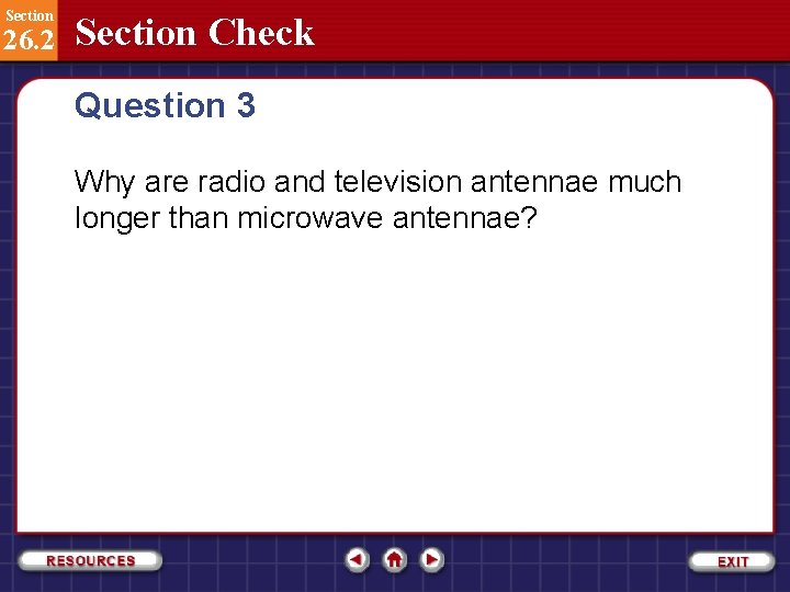
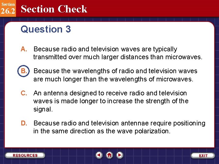
Section 26. 2 Section Check Question 3 Why are radio and television antennae much longer than microwave antennae?

Section 26. 2 Section Check Question 3 A. Because radio and television waves are typically transmitted over much larger distances than microwaves. B. Because the wavelengths of radio and television waves are much longer than the wavelengths of microwaves. C. An antenna designed to receive radio and television waves is made longer to increase the strength of the signal. D. Because radio and television antennae require positioning in the same direction as the wave polarization.

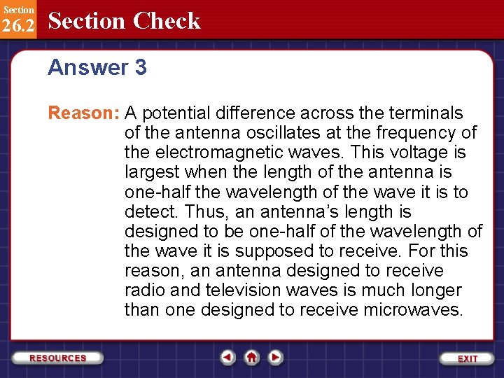
Section 26. 2 Section Check Answer 3 Reason: A potential difference across the terminals of the antenna oscillates at the frequency of the electromagnetic waves. This voltage is largest when the length of the antenna is one-half the wavelength of the wave it is to detect. Thus, an antenna’s length is designed to be one-half of the wavelength of the wave it is supposed to receive. For this reason, an antenna designed to receive radio and television waves is much longer than one designed to receive microwaves.

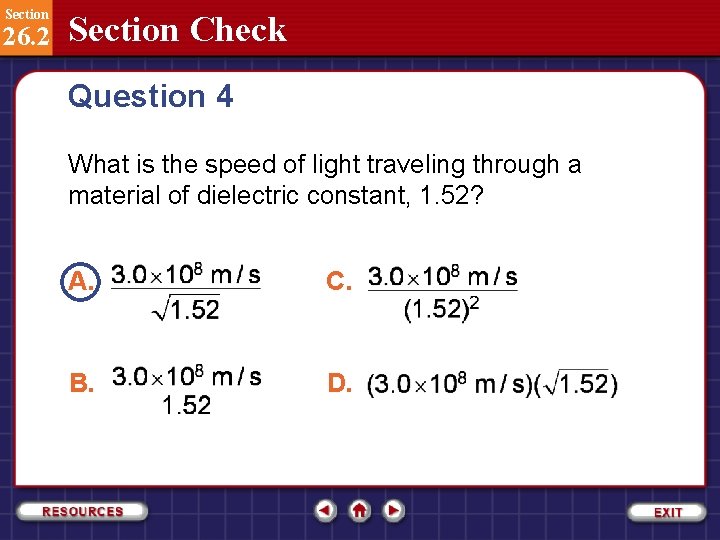
Section 26. 2 Section Check Question 4 What is the speed of light traveling through a material of dielectric constant, 1. 52? A. C. B. D.

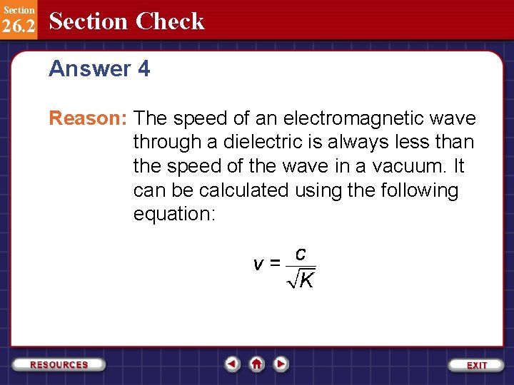
Section 26. 2 Section Check Answer 4 Reason: The speed of an electromagnetic wave through a dielectric is always less than the speed of the wave in a vacuum. It can be calculated using the following equation:

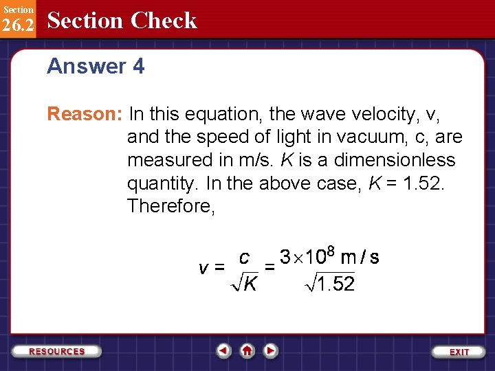
Section 26. 2 Section Check Answer 4 Reason: In this equation, the wave velocity, v, and the speed of light in vacuum, c, are measured in m/s. K is a dimensionless quantity. In the above case, K = 1. 52. Therefore,

Section 26. 2 Section Check

Section 26. 1 Interactions of Electric and Magnetic Fields and Matter Path Radius An electron with a mass of 9. 11× 10 -31 kg moves through a cathode-ray tube at 2. 0× 105 m/s perpendicular to a magnetic field of 3. 5× 10 -2 T. The electric field is turned off. What is the radius of the circular path that is followed by the electron? Click the Back button to return to original slide.

Section 26. 1 Interactions of Electric and Magnetic Fields and Matter Mass of a Neon Atom The operator of a mass spectrometer produces a beam of doubly ionized (2+) neon atoms. They first are accelerated by a potential difference of 34 V. Then, as the ions pass through a magnetic field of 0. 050 T, the radius of their path is 53 mm. Determine the mass of the neon atom to the closest whole number of proton masses. Click the Back button to return to original slide.
