Validation 1 In the pharmaceutical medical device food

- Slides: 127
Validation 1
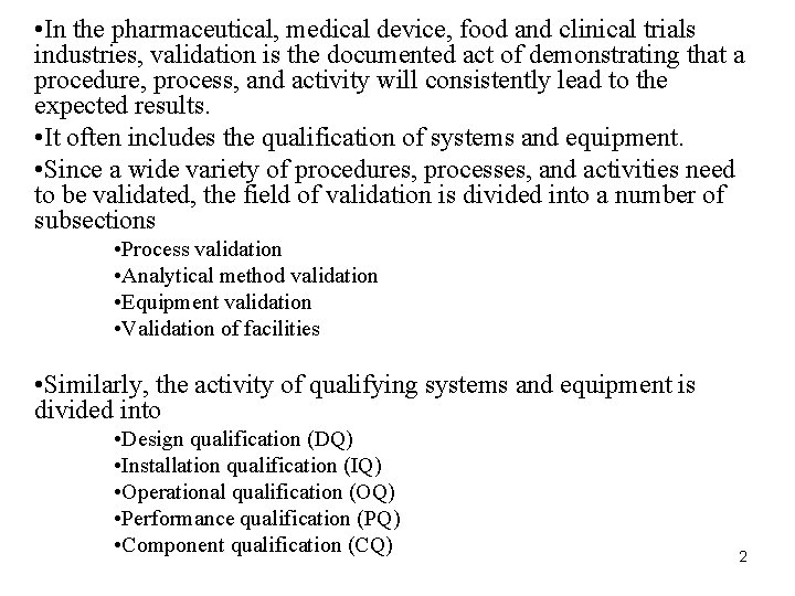
• In the pharmaceutical, medical device, food and clinical trials industries, validation is the documented act of demonstrating that a procedure, process, and activity will consistently lead to the expected results. • It often includes the qualification of systems and equipment. • Since a wide variety of procedures, processes, and activities need to be validated, the field of validation is divided into a number of subsections • Process validation • Analytical method validation • Equipment validation • Validation of facilities • Similarly, the activity of qualifying systems and equipment is divided into • Design qualification (DQ) • Installation qualification (IQ) • Operational qualification (OQ) • Performance qualification (PQ) • Component qualification (CQ) 2
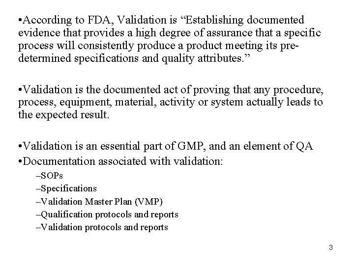
• According to FDA, Validation is “Establishing documented evidence that provides a high degree of assurance that a specific process will consistently produce a product meeting its predetermined specifications and quality attributes. ” • Validation is the documented act of proving that any procedure, process, equipment, material, activity or system actually leads to the expected result. • Validation is an essential part of GMP, and an element of QA • Documentation associated with validation: –SOPs –Specifications –Validation Master Plan (VMP) –Qualification protocols and reports –Validation protocols and reports 3
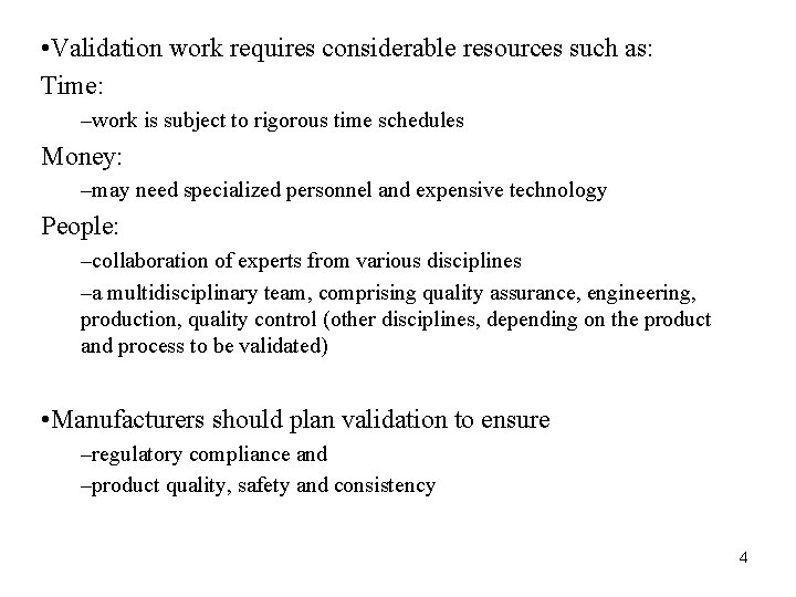
• Validation work requires considerable resources such as: Time: –work is subject to rigorous time schedules Money: –may need specialized personnel and expensive technology People: –collaboration of experts from various disciplines –a multidisciplinary team, comprising quality assurance, engineering, production, quality control (other disciplines, depending on the product and process to be validated) • Manufacturers should plan validation to ensure –regulatory compliance and –product quality, safety and consistency 4
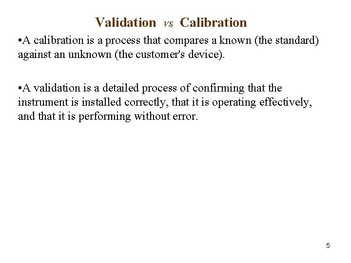
Validation VS Calibration • A calibration is a process that compares a known (the standard) against an unknown (the customer's device). • A validation is a detailed process of confirming that the instrument is installed correctly, that it is operating effectively, and that it is performing without error. 5
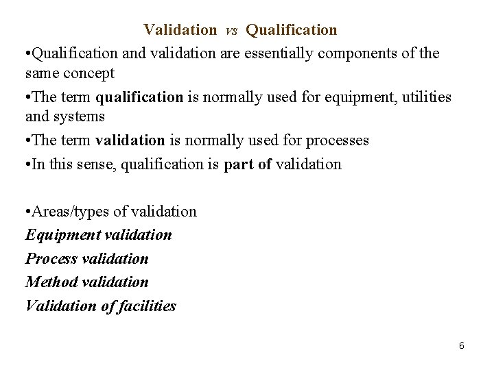
Validation VS Qualification • Qualification and validation are essentially components of the same concept • The term qualification is normally used for equipment, utilities and systems • The term validation is normally used for processes • In this sense, qualification is part of validation • Areas/types of validation Equipment validation Process validation Method validation Validation of facilities 6
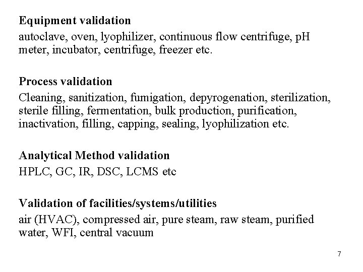
Equipment validation autoclave, oven, lyophilizer, continuous flow centrifuge, p. H meter, incubator, centrifuge, freezer etc. Process validation Cleaning, sanitization, fumigation, depyrogenation, sterilization, sterile filling, fermentation, bulk production, purification, inactivation, filling, capping, sealing, lyophilization etc. Analytical Method validation HPLC, GC, IR, DSC, LCMS etc Validation of facilities/systems/utilities air (HVAC), compressed air, pure steam, raw steam, purified water, WFI, central vacuum 7
Equipment validation • Each equipment must be validated in order to legally operate within the facility. • The goal is to produce consistent results with minimal variation without compromising the integrity of the product and the persons operating the equipment. • A plan of validation should be drafted and executed by engineers in order to satisfy guidelines. The validation plan generally consists of DQ, IQ, OQ, PQ and CQ sections. • Any major equipment changes after the initial validation will result in the need for subsequent revalidation. • In the end, equipment validation will create specification ranges and tolerances that will be applied to the normal operation of equipment. 8
Design qualification (DQ)- Demonstrates that the proposed design (or the existing design) will satisfy all the requirements that are defined and detailed in the User Requirements Specification (URS). Satisfactory execution of the DQ is a mandatory requirement before construction (or procurement) of the new design can be authorised. Installation qualification (IQ) – Demonstrates that the process or equipment meets all specifications, is installed correctly, and to the original manufacturer’s specifications. Calibration of major equipment, accessory equipment, and/or utilities should be performed in this step as well. 9
Operational Qualification (OQ)-In the OQ, tests are performed on the critical parameters of the system/process. These are usually the independent and/or manipulated variables associated with the system/equipment. All tests’ data and measurements must be documented in order to set a baseline for the system/equipment. The completion of satisfactory IQ and OQ exercises should permit a formal "release" of the equipment for the next stage in the process validation exercise as long as calibration, cleaning, preventive maintenance and operator training requirements have been finalised and documented. 10
Performance qualification (PQ) – Demonstrates that the process or equipment performs as intended in a consistent manner over long periods of time. PQ is performed on the manufacturing process as a whole. Individual components of the system are not tested individually. Component qualification (CQ) – is a relatively new term developed in 2005. This term refers to the manufacturing of auxiliary components to ensure that they are manufactured to the correct design criteria. This could include packaging components such as folding cartons, shipping cases, labels or even phase change material. All of these components must have some type of random inspection to ensure that the third party manufacturer's process is consistently producing components that are used in the world of GMP at drug or biologic manufacturer. 11
Process validation • The manufacturing process, in addition to the individual equipment, must be validated. • The goal is to create a robust manufacturing process that consistently produces a drug product with minimal variation that adheres to quality criteria of purity, identity, and potency. • A validation plan for the manufacturing process should be drafted and executed in order to satisfy guidelines. The validation plan usually involves just a PQ section. • Just as equipment validation, major changes after the initial validation will result in the need for subsequent revalidation. • In the end, process validation will ensure a robust product that is highly reproducible over time. • Types –Prospective validation –Concurrent validation –Retrospective validation –Revalidation 12
Prospective validation • Here the validation protocol is executed before the process is put into commercial use. • During the product development phase the production process should be broken down into individual steps. Each step should be evaluated to determine the critical parameters that may affect the quality of the finished product. • All equipment, production environment and the analytical testing methods to be used should have been fully validated. • Master batch documents can be prepared only after the critical parameters of the process have been identified and machine settings, component specifications and environmental conditions have been determined. 13
• It is generally considered acceptable that three consecutive batches/runs within the finally agreed parameters, giving product of the desired quality would constitute a proper validation of the process. • During the processing of the validation batches, extensive sampling and testing should be performed on the product at various stages, and should be documented comprehensively. • Detailed testing should also be done on the final product in its package. 14
Concurrent Validation (validation while production) • FDA considers concurrent validation to be a subset of prospective validation. • Concurrent validation may be conducted on a previously validated process to confirm that the process is validated. • Concurrent validation may be the practical approach under certain circumstances. Examples of these may be: –when a previously validated process is being transferred to a third party contract manufacturer or to another manufacturing site –where the product is a different strength of a previously validated product with the same ratio of active / inactive ingredients –when the number of lots evaluated under the retrospective validation were not sufficient to obtain a high degree of assurance demonstrating that the process is fully under control –when the number of batches produced are limited (e. g. orphan drugs). 15
Retrospective Validation In many establishments, processes that are stable and in routine use have not undergone a formally documented validation process. Historical data may be utilized to provide necessary documentary evidence that the processes are validated. Retrospective validation involves the examination of past experience of production The source of data for retrospective validation should include amongst others, batch documents, process control charts, annual product quality review reports, maintenance log books, process capability studies, finished product test results, including trend analyses, and stability results. 16
Some of the essential elements for retrospective validation are: • Batches manufactured for a defined period (minimum of 10 last consecutive batches) • Number of lots released per year • Batch size/strength/manufacturer/year/period • Master manufacturing/packaging documents • Current specifications for active materials/finished products • List of process deviations, corrective actions and changes to manufacturing documents • Data for stability testing for several batches 17
Revalidation • Re-validation provides the evidence that changes in a process and /or the process environment that are introduced do not adversely affect process characteristics and product quality. • Examples of some of the planned or unplanned changes that may require re-validation: –Changes in raw materials (physical properties such as density, viscosity, particle size distribution, and moisture, etc. , that may affect the process or product). –Changes in the source of active raw material manufacturer –Changes in packaging material (primary container/closure system). –Changes in the process (e. g. , mixing time, drying temperatures and batch size) –Changes in the equipment (e. g. addition of automatic detection system). Changes of equipment which involve the replacement of equipment on a "like for like" basis would not normally require a re-validation except that this new equipment must be qualified. –Changes in the plant/facility. –Variations revealed by trend analysis (e. g. process drifts) 18
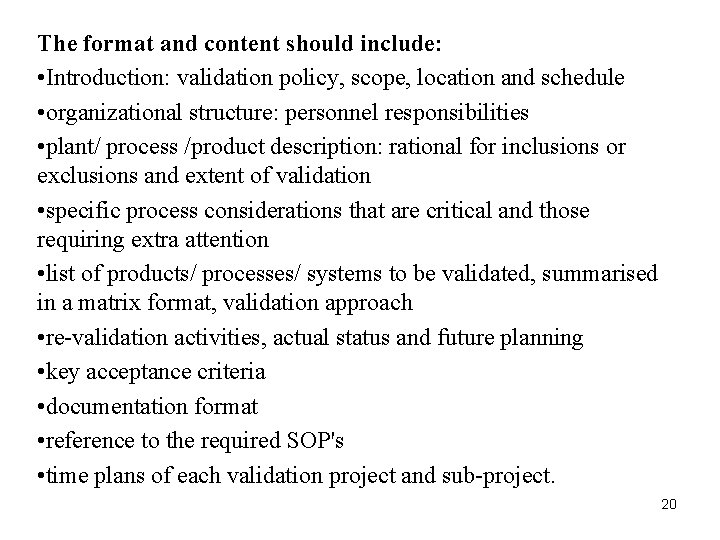
Validation Master Plan • The validation master plan should provide an overview of the entire validation operation, its organizational structure, its content and planning. • The main elements of it being the list/inventory of the items to be validated and the planning schedule. • All validation activities relating to critical technical operations, relevant to product and process controls within a firm should be included in the validation master plan. • It should comprise all prospective, concurrent and retrospective validations as well as re-validation. • The validation master plan should be a summary document and should therefore be brief, concise and clear. • It should not repeat information documented elsewhere but should refer to existing documents such as policy documents, SOP's and validation protocols and reports. 19
The format and content should include: • Introduction: validation policy, scope, location and schedule • organizational structure: personnel responsibilities • plant/ process /product description: rational for inclusions or exclusions and extent of validation • specific process considerations that are critical and those requiring extra attention • list of products/ processes/ systems to be validated, summarised in a matrix format, validation approach • re-validation activities, actual status and future planning • key acceptance criteria • documentation format • reference to the required SOP's • time plans of each validation project and sub-project. 20
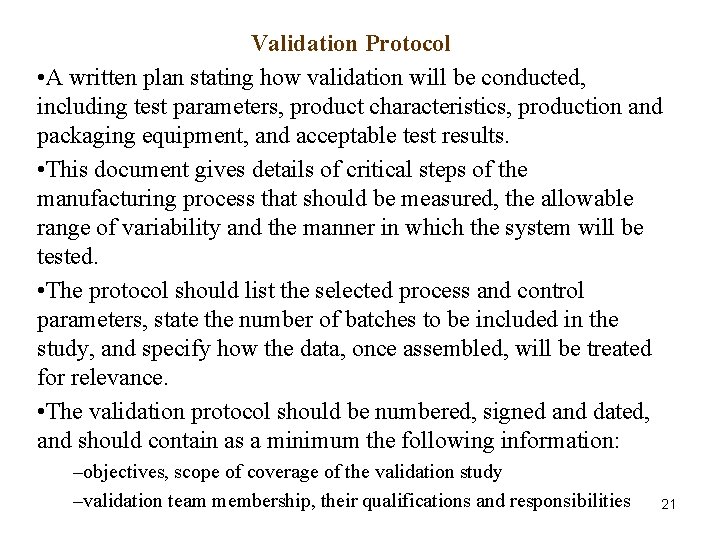
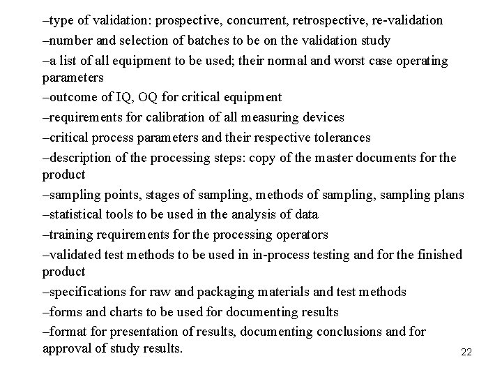
Validation Protocol • A written plan stating how validation will be conducted, including test parameters, product characteristics, production and packaging equipment, and acceptable test results. • This document gives details of critical steps of the manufacturing process that should be measured, the allowable range of variability and the manner in which the system will be tested. • The protocol should list the selected process and control parameters, state the number of batches to be included in the study, and specify how the data, once assembled, will be treated for relevance. • The validation protocol should be numbered, signed and dated, and should contain as a minimum the following information: –objectives, scope of coverage of the validation study –validation team membership, their qualifications and responsibilities 21
–type of validation: prospective, concurrent, retrospective, re-validation –number and selection of batches to be on the validation study –a list of all equipment to be used; their normal and worst case operating parameters –outcome of IQ, OQ for critical equipment –requirements for calibration of all measuring devices –critical process parameters and their respective tolerances –description of the processing steps: copy of the master documents for the product –sampling points, stages of sampling, methods of sampling, sampling plans –statistical tools to be used in the analysis of data –training requirements for the processing operators –validated test methods to be used in in-process testing and for the finished product –specifications for raw and packaging materials and test methods –forms and charts to be used for documenting results –format for presentation of results, documenting conclusions and for approval of study results. 22
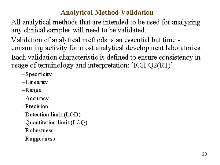
Analytical Method Validation All analytical methods that are intended to be used for analyzing any clinical samples will need to be validated. Validation of analytical methods is an essential but time consuming activity for most analytical development laboratories. Each validation characteristic is defined to ensure consistency in usage of terminology and interpretation: [ICH Q 2(R 1)] –Specificity –Linearity –Range –Accuracy –Precision –Detection limit (LOD) –Quantitation limit (LOQ) –Robustness –Ruggedness 23
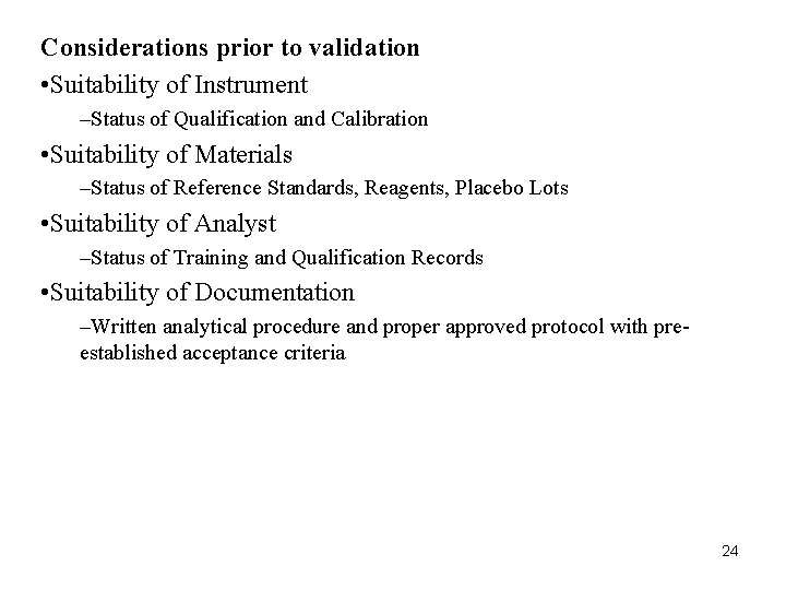
Considerations prior to validation • Suitability of Instrument –Status of Qualification and Calibration • Suitability of Materials –Status of Reference Standards, Reagents, Placebo Lots • Suitability of Analyst –Status of Training and Qualification Records • Suitability of Documentation –Written analytical procedure and proper approved protocol with preestablished acceptance criteria 24
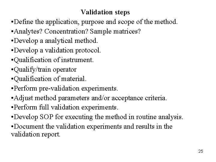
Validation steps • Define the application, purpose and scope of the method. • Analytes? Concentration? Sample matrices? • Develop a analytical method. • Develop a validation protocol. • Qualification of instrument. • Qualify/train operator • Qualification of material. • Perform pre-validation experiments. • Adjust method parameters and/or acceptance criteria. • Perform full validation experiments. • Develop SOP for executing the method in routine analysis. • Document the validation experiments and results in the validation report. 25
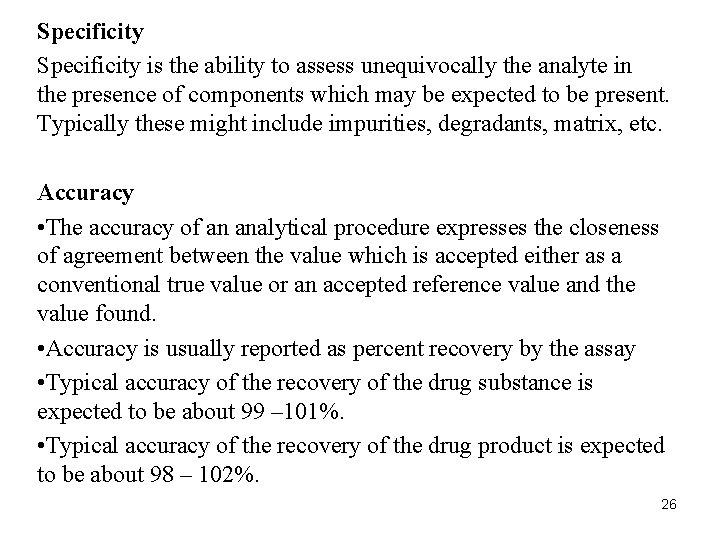
Specificity is the ability to assess unequivocally the analyte in the presence of components which may be expected to be present. Typically these might include impurities, degradants, matrix, etc. Accuracy • The accuracy of an analytical procedure expresses the closeness of agreement between the value which is accepted either as a conventional true value or an accepted reference value and the value found. • Accuracy is usually reported as percent recovery by the assay • Typical accuracy of the recovery of the drug substance is expected to be about 99 – 101%. • Typical accuracy of the recovery of the drug product is expected to be about 98 – 102%. 26
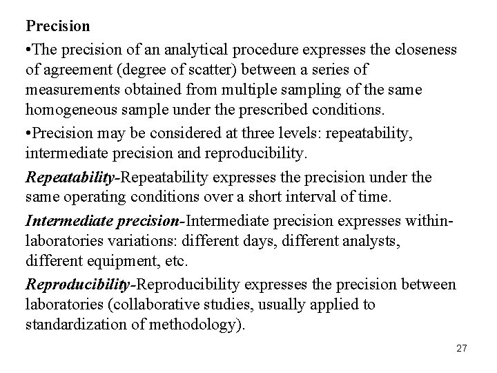
Precision • The precision of an analytical procedure expresses the closeness of agreement (degree of scatter) between a series of measurements obtained from multiple sampling of the same homogeneous sample under the prescribed conditions. • Precision may be considered at three levels: repeatability, intermediate precision and reproducibility. Repeatability-Repeatability expresses the precision under the same operating conditions over a short interval of time. Intermediate precision-Intermediate precision expresses withinlaboratories variations: different days, different analysts, different equipment, etc. Reproducibility-Reproducibility expresses the precision between laboratories (collaborative studies, usually applied to standardization of methodology). 27
Detection Limit (Limit of Detection) • The detection limit of an individual analytical procedure is the lowest amount of analyte in a sample which can be detected. • Some of the approaches used are: –Based on Visual Evaluation –Based on Signal-to-Noise –Based on the Standard Deviation of the Response and the Slope –Recommended Data 28
Quantitation Limit (Limit of Quantitation) • The quantitation limit of an individual analytical procedure is the lowest amount of analyte in a sample which can be quantitatively determined with suitable precision and accuracy. • The quantitation limit is a parameter of quantitative assays for low levels of compounds in sample matrices, and is used particularly for the determination of impurities and/or degradation products. • Some of the approaches used are: –Based on Visual Evaluation –Based on Signal-to-Noise approach –Based on the Standard Deviation of the Response and the Slope –Recommended Data 29
Linearity • The linearity of an analytical procedure is its ability (within a given range) to obtain test results which are directly proportional to the concentration (amount) of analyte in the sample. • Under normal circumstances, linearity is acceptable with a coefficient of determination (r 2) of ≥ 0. 997. Range • The range of an analytical procedure is the interval between the upper and lower concentration (amounts) of analyte in the sample. • The following minimum specified ranges should be considered: - for the assay of a drug substance or a finished (drug) product: normally from 80 to 120 percent of the test concentration; 30
- for content uniformity, covering a minimum of 70 to 130 percent of the test concentration, unless a wider more appropriate range, based on the nature of the dosage form (e. g. , metered dose inhalers), is justified; - for dissolution testing: +/-20 % over the specified range; e. g. , if the specifications for a controlled released product cover a region from 20%, after 1 hour, up to 90%, after 24 hours, the validated range would be 0 -110% of the label claim. 31
Robustness • The robustness of an analytical procedure is a measure of its capacity to remain unaffected by small, but deliberate variations in method parameters and provides an indication of its reliability during normal usage. • In the case of liquid chromatography, examples of typical variations are: - influence of variations of p. H in a mobile phase; - influence of variations in mobile phase composition; - different columns (different lots and/or suppliers); - temperature; - flow rate. • In the case of gas-chromatography, examples of typical variations are: - different columns (different lots and/or suppliers); - temperature; - flow rate. 32
Ruggedness • the degreeof reproducibility of test results obtained bythe analysis of the Same samples under a variety of normal test conditions such as: –Different laboratories –Different analysts –Different instruments –Different reagent lots –Different analysis days –Different assay temperatures etc. 33
Validation of facilities Compressed Air • Compressed air is an important component of pharmaceutical manufacturing facilities • It provides many of the air types necessary for a manufacturing facility to function, including: breathing air , motive air for machines , process air , analytical air and Product Direct Impact , or "c. GMP" air • The application for which the compressed air will be used will dictate the level of air quality that is appropriate for use 34
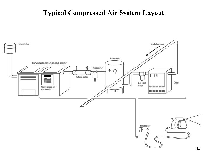
Typical Compressed Air System Layout 35
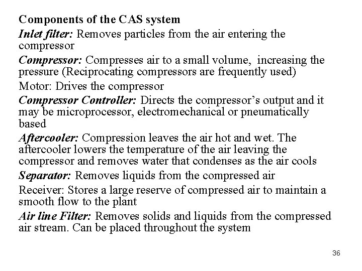
Components of the CAS system Inlet filter: Removes particles from the air entering the compressor Compressor: Compresses air to a small volume, increasing the pressure (Reciprocating compressors are frequently used) Motor: Drives the compressor Controller: Directs the compressor’s output and it may be microprocessor, electromechanical or pneumatically based Aftercooler: Compression leaves the air hot and wet. The aftercooler lowers the temperature of the air leaving the compressor and removes water that condenses as the air cools Separator: Removes liquids from the compressed air Receiver: Stores a large reserve of compressed air to maintain a smooth flow to the plant Air line Filter: Removes solids and liquids from the compressed air stream. Can be placed throughout the system 36
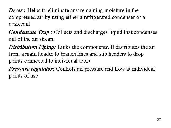
Dryer : Helps to eliminate any remaining moisture in the compressed air by using either a refrigerated condenser or a desiccant Condensate Trap : Collects and discharges liquid that condenses out of the air stream Distribution Piping: Links the components. It distributes the air from a main header to branch lines and sub headers to drop points connected to individual tools Pressure regulator: Controls air pressure and flow at individual points of use 37
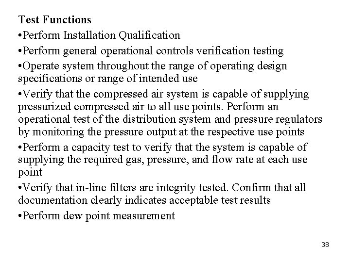
Test Functions • Perform Installation Qualification • Perform general operational controls verification testing • Operate system throughout the range of operating design specifications or range of intended use • Verify that the compressed air system is capable of supplying pressurized compressed air to all use points. Perform an operational test of the distribution system and pressure regulators by monitoring the pressure output at the respective use points • Perform a capacity test to verify that the system is capable of supplying the required gas, pressure, and flow rate at each use point • Verify that in-line filters are integrity tested. Confirm that all documentation clearly indicates acceptable test results • Perform dew point measurement 38
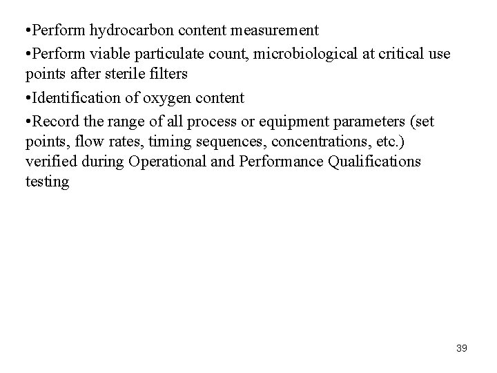
• Perform hydrocarbon content measurement • Perform viable particulate count, microbiological at critical use points after sterile filters • Identification of oxygen content • Record the range of all process or equipment parameters (set points, flow rates, timing sequences, concentrations, etc. ) verified during Operational and Performance Qualifications testing 39
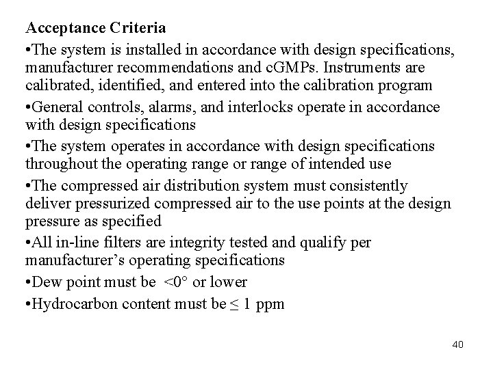
Acceptance Criteria • The system is installed in accordance with design specifications, manufacturer recommendations and c. GMPs. Instruments are calibrated, identified, and entered into the calibration program • General controls, alarms, and interlocks operate in accordance with design specifications • The system operates in accordance with design specifications throughout the operating range or range of intended use • The compressed air distribution system must consistently deliver pressurized compressed air to the use points at the design pressure as specified • All in-line filters are integrity tested and qualify per manufacturer’s operating specifications • Dew point must be <0° or lower • Hydrocarbon content must be ≤ 1 ppm 40
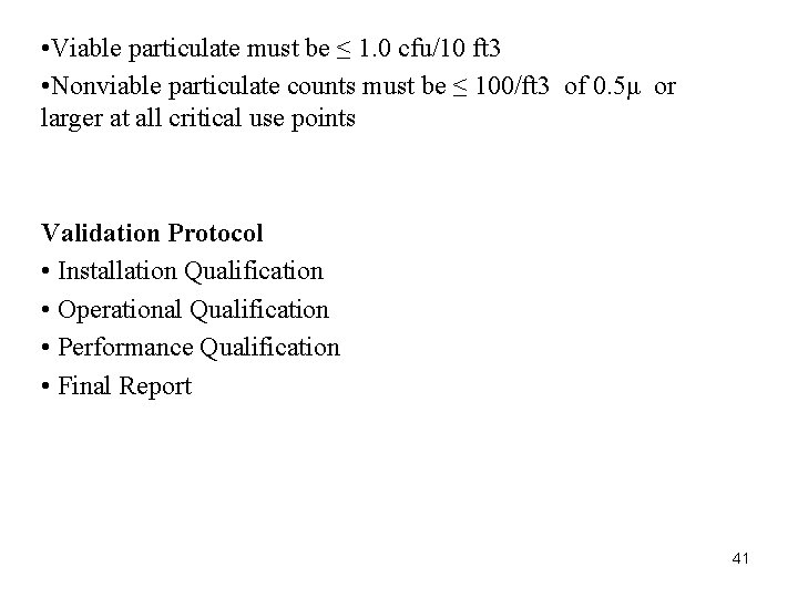
• Viable particulate must be ≤ 1. 0 cfu/10 ft 3 • Nonviable particulate counts must be ≤ 100/ft 3 of 0. 5μ or larger at all critical use points Validation Protocol • Installation Qualification • Operational Qualification • Performance Qualification • Final Report 41
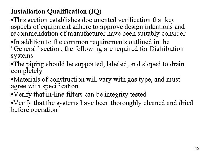
Installation Qualification (IQ) • This section establishes documented verification that key aspects of equipment adhere to approve design intentions and recommendation of manufacturer have been suitably consider • In addition to the common requirements outlined in the "General" section, the following are required for Distribution systems • The piping should be supported, labeled, and sloped to drain completely • Materials of construction will vary with gas type, and must agree with specification • Verify that in-line filters can be integrity tested • Verify that the systems have been thoroughly cleaned and dried before operation 42
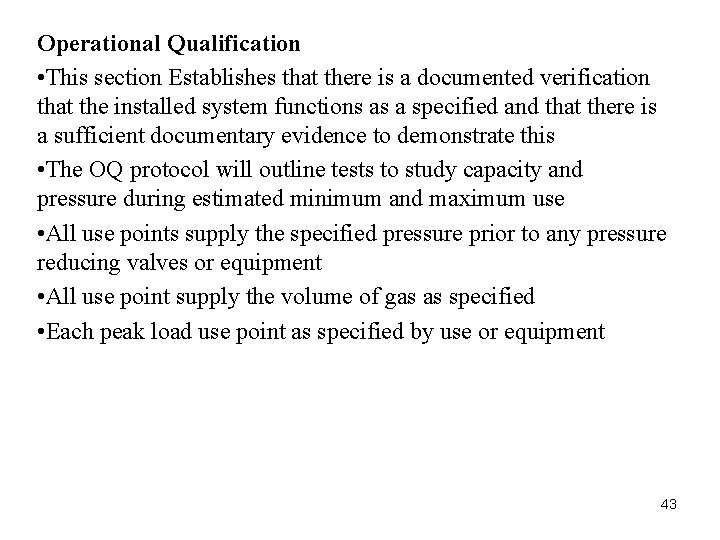
Operational Qualification • This section Establishes that there is a documented verification that the installed system functions as a specified and that there is a sufficient documentary evidence to demonstrate this • The OQ protocol will outline tests to study capacity and pressure during estimated minimum and maximum use • All use points supply the specified pressure prior to any pressure reducing valves or equipment • All use point supply the volume of gas as specified • Each peak load use point as specified by use or equipment 43
Performance Qualification • This section gives documented verification that the equipment performance in its normal operating environment is consistently exactly as specified in User Requirement Specification (URS) • Testing will include viable and total particulate counts, dew point, hydrocarbon analysis, and purity analysis • Each point of use will be tested at least three times over 10 working days. Every use point of the system must be tested several times over the course of the study. • Hydrocarbon Monitoring should show less than 0. 2 mg/m 3 (25 mg/125 liters) detected. (the lower limit of a Dragger tube) • The highest total particulate count from the five one-minute runs must meet class 100 or EC Class A criteria • Viable Monitoring (not needed of integrity tested final filter is in place) less than 0. 03 CFU/ft 3 or less than 1 CFU/m 3 44
• Since the gas is field sampled under non-sterile conditions, a few sporadic, individual, tests may fail. Persistent test failures with any individual test, or group of tests, will indicate a system failure • The dew point of compressed air less than or equal to -10°C, or less than the lowest temperature to which the system is exposed • Identity and Purity (Nitrogen) Not less than 99. 0% nitrogen by volume. Not more than 0. 001% Carbon Monoxide. No appreciable odor • Identity and Purity (Oxygen) Not less than 99. 0% Oxygen by volume. No appreciable odor Final Report Depending on IQ , OQ and PQ data final report is made and that will indicate whether your system is validated or not 45
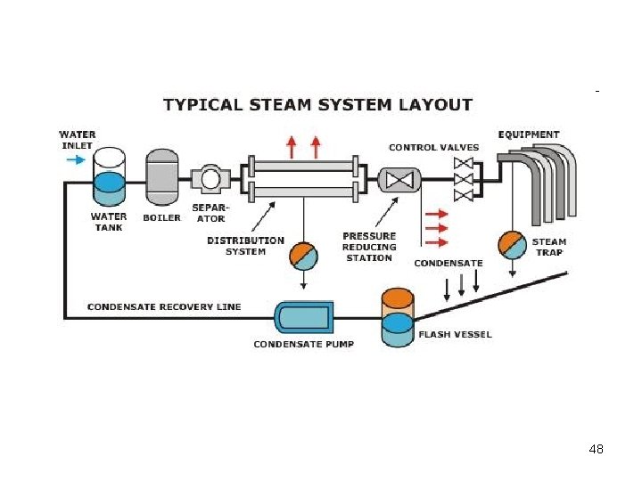
Validation of facilities Steam • Steam remains today the prime carrier of heat for the process industries, from food and dairy to biotechnology and pharmaceuticals. • Normal factory or plant steam may contain small quantities of boiler feed water chemicals and traces of pipe scale and other debris which may not be acceptable in the production of the injectables or parenteral solutions, which are always sterile. • In the production of these parenteral solutions, quality and purity of steam is of utmost importance, and special care need to be taken for the generation of this kind of steam. 46
Clean steam is typically used for • Sterilization of reactors, tanks and piping • Maintaining Sterile barriers using block and bleed system • Sterilization of process equipments. • Autoclave / Sterilizer • Direct heating and cooking. • Pasteurizing • Humidification. 47
48
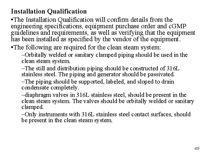
Installation Qualification • The Installation Qualification will confirm details from the engineering specifications, equipment purchase order and c. GMP guidelines and requirements, as well as verifying that the equipment has been installed as specified by the vendor of the equipment. • The following are required for the clean steam system: –Orbitally welded or sanitary clamped piping should be used in the clean steam system. –The still and distribution piping should be constructed of 316 L stainless steel. The piping and generator should be passivated. –The piping should be supported, labeled, and sloped to drain condensate completely. –diaphragm valves in 316 L stainless steel, should be present in the clean steam system. The valves should be orbitally welded or sanitary clamped. –Only instruments with 316 L stainless steel contact surfaces, should be present in the clean steam system. 49
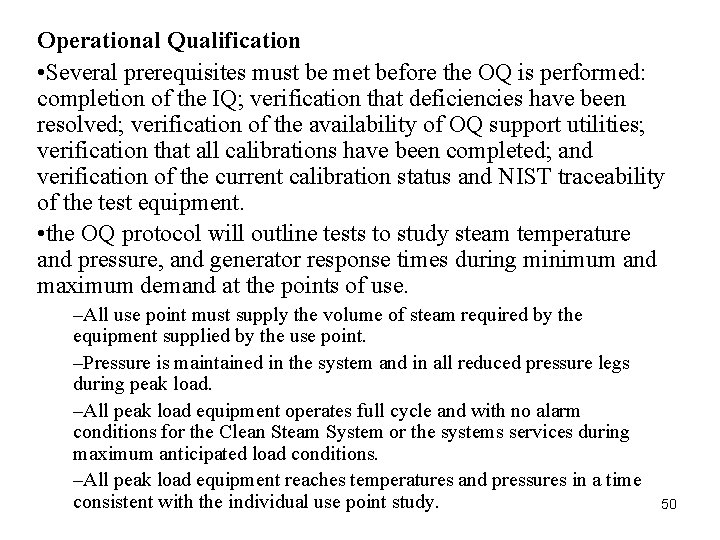
Operational Qualification • Several prerequisites must be met before the OQ is performed: completion of the IQ; verification that deficiencies have been resolved; verification of the availability of OQ support utilities; verification that all calibrations have been completed; and verification of the current calibration status and NIST traceability of the test equipment. • the OQ protocol will outline tests to study steam temperature and pressure, and generator response times during minimum and maximum demand at the points of use. –All use point must supply the volume of steam required by the equipment supplied by the use point. –Pressure is maintained in the system and in all reduced pressure legs during peak load. –All peak load equipment operates full cycle and with no alarm conditions for the Clean Steam System or the systems services during maximum anticipated load conditions. –All peak load equipment reaches temperatures and pressures in a time consistent with the individual use point study. 50
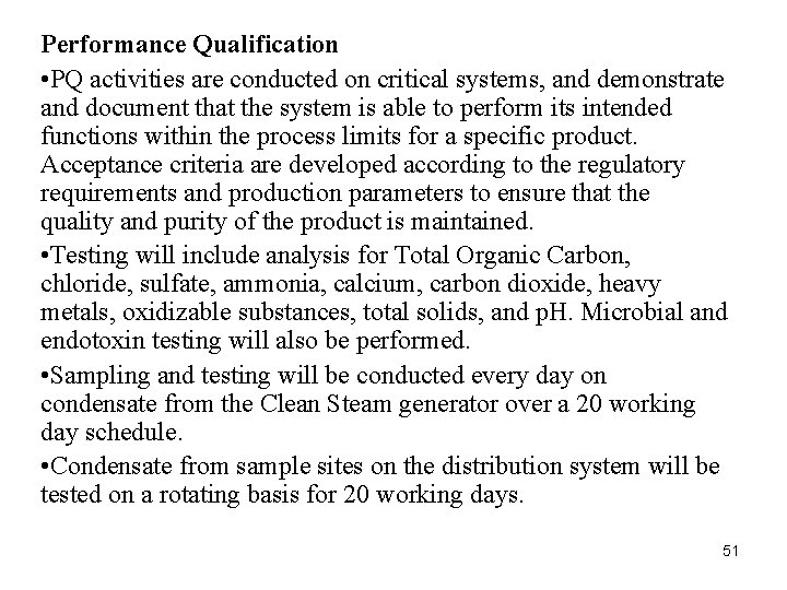
Performance Qualification • PQ activities are conducted on critical systems, and demonstrate and document that the system is able to perform its intended functions within the process limits for a specific product. Acceptance criteria are developed according to the regulatory requirements and production parameters to ensure that the quality and purity of the product is maintained. • Testing will include analysis for Total Organic Carbon, chloride, sulfate, ammonia, calcium, carbon dioxide, heavy metals, oxidizable substances, total solids, and p. H. Microbial and endotoxin testing will also be performed. • Sampling and testing will be conducted every day on condensate from the Clean Steam generator over a 20 working day schedule. • Condensate from sample sites on the distribution system will be tested on a rotating basis for 20 working days. 51
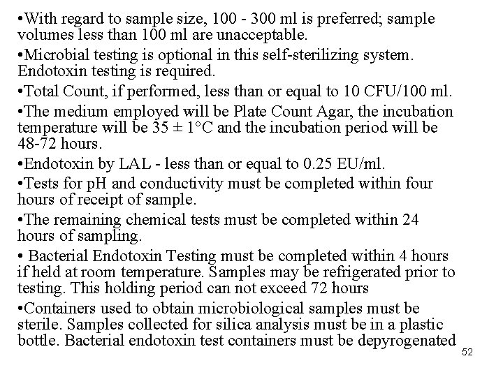
• With regard to sample size, 100 - 300 ml is preferred; sample volumes less than 100 ml are unacceptable. • Microbial testing is optional in this self-sterilizing system. Endotoxin testing is required. • Total Count, if performed, less than or equal to 10 CFU/100 ml. • The medium employed will be Plate Count Agar, the incubation temperature will be 35 ± 1°C and the incubation period will be 48 -72 hours. • Endotoxin by LAL - less than or equal to 0. 25 EU/ml. • Tests for p. H and conductivity must be completed within four hours of receipt of sample. • The remaining chemical tests must be completed within 24 hours of sampling. • Bacterial Endotoxin Testing must be completed within 4 hours if held at room temperature. Samples may be refrigerated prior to testing. This holding period can not exceed 72 hours • Containers used to obtain microbiological samples must be sterile. Samples collected for silica analysis must be in a plastic bottle. Bacterial endotoxin test containers must be depyrogenated 52
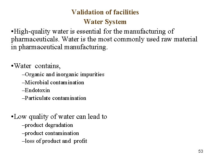
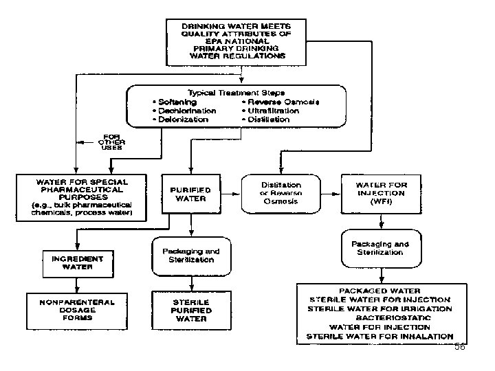
Validation of facilities Water System • High-quality water is essential for the manufacturing of pharmaceuticals. Water is the most commonly used raw material in pharmaceutical manufacturing. • Water contains, –Organic and inorganic impurities –Microbial contamination –Endotoxin –Particulate contamination • Low quality of water can lead to –product degradation –product contamination –loss of product and profit 53
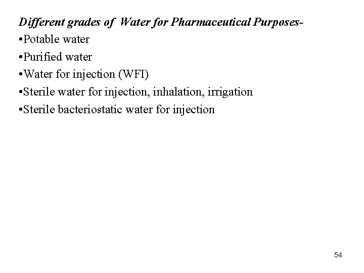
Different grades of Water for Pharmaceutical Purposes • Potable water • Purified water • Water for injection (WFI) • Sterile water for injection, inhalation, irrigation • Sterile bacteriostatic water for injection 54
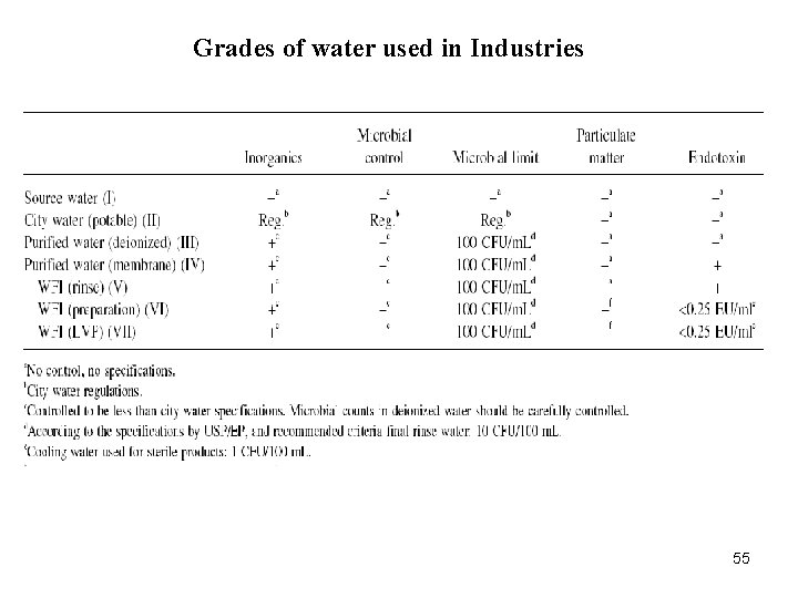
Grades of water used in Industries 55
56
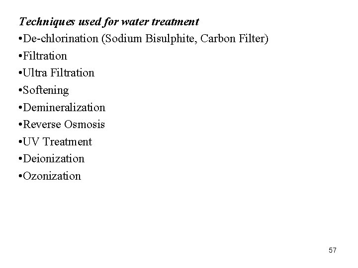
Techniques used for water treatment • De-chlorination (Sodium Bisulphite, Carbon Filter) • Filtration • Ultra Filtration • Softening • Demineralization • Reverse Osmosis • UV Treatment • Deionization • Ozonization 57
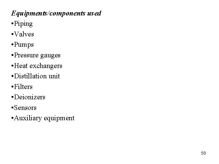
Equipments/components used • Piping • Valves • Pumps • Pressure gauges • Heat exchangers • Distillation unit • Filters • Deionizers • Sensors • Auxiliary equipment 58
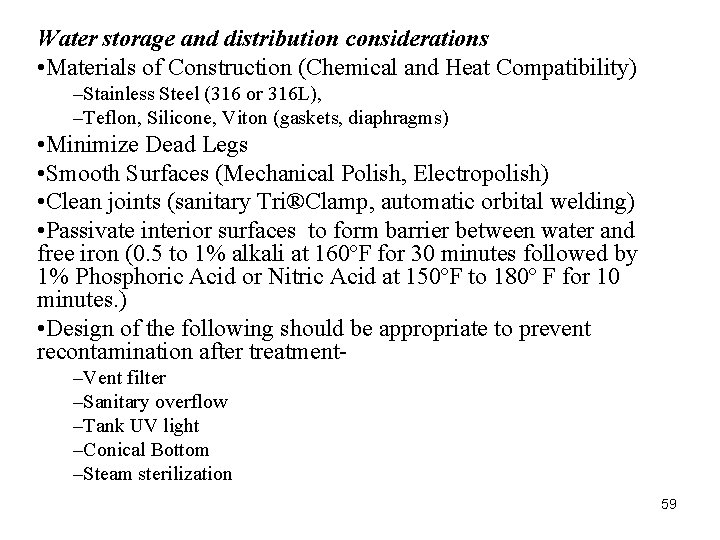
Water storage and distribution considerations • Materials of Construction (Chemical and Heat Compatibility) –Stainless Steel (316 or 316 L), –Teflon, Silicone, Viton (gaskets, diaphragms) • Minimize Dead Legs • Smooth Surfaces (Mechanical Polish, Electropolish) • Clean joints (sanitary Tri®Clamp, automatic orbital welding) • Passivate interior surfaces to form barrier between water and free iron (0. 5 to 1% alkali at 160ºF for 30 minutes followed by 1% Phosphoric Acid or Nitric Acid at 150ºF to 180º F for 10 minutes. ) • Design of the following should be appropriate to prevent recontamination after treatment–Vent filter –Sanitary overflow –Tank UV light –Conical Bottom –Steam sterilization 59
Validation Protocol • Installation Qualification • Operational Qualification • Performance Qualification • Re-qualification • Final Report 60
Installation Qualification • IQ is in the form of checklist and it should include • Instrumentation checked against current engineering drawings and specifications • Review of P&ID • Verification of materials of construction • Installation of equipment with piping • Calibration of measuring instruments • Collection and collation of supplier operating and working instructions and maintenance requirements • Installation of system as per Design requirements. Installation Verification • Systematic range of adjustments, measurements and tests should be carried out to ensure proper installation. • Documentation include details of completed installation. 61
IQ Document should contain • Instrument name, model, I. D. No. , Personnel responsible for activities and Date. • A fully verified installation that complies with the documented design. (all deviations will have been recorded and assessed. ) • All equipment documentation and maintenance requirements would be documented. • Completed calibration of measuring instruments. • Verification of Materials of construction. 62
Operational Qualification • The purpose of OQ is to establish, through documented testing, that all critical components are capable of operating within established limits and tolerances. • It is the functional testing of system components mainly the critical components. • The purpose of OQ is also to verify and document that the water supply system provides acceptable operational control under “atrest” conditions. Operation Qualification Checks–Ability to provide water of sufficient quality and quantity to ensure achievement of specifications. –Ability to maintain general parameters like temperature, pressure, flow at set points. –Ability to maintain any critical parameters(p. H, TOC, endotoxin, microbial level, conductivity etc ). 63
Performance Qualification • The purpose of PQ is to verify and document that water supply system provides acceptable control under ‘ Full Operational ‘ conditions. • PQ should follow successful completion of IQ and OQ. • PQ verifies that over time, the critical parameters, as defined in the DQ are being achieved. Monitoring • Monitoring and feed back data are important in maintaining the performance systems. • Monitoring parameters include: –Flow, pressure, temperature, conductivity, TOC • Samples taken: –From points of use, and specific sample points 64
• Tests should include physical, chemical and microbial attributes • For example, stable state can be achieved by applying automatic continuous monitoring of TOC and conductivity of the water system. They are the major quality attributes of water by which organic and inorganic impurities can be determined. Revalidation –Once the validation is completed, the standard operating procedures (SOPs) are formalized. –Routine operation should be performed according to the established SOP. –If any deviation from SOP observed, determine the change and their impact on whole system –Revalidation and evaluation should be performed depending upon the impact of the change on system. 65
Validation Report • Executive summary • Discussion • Conclusions & recommendation • List of attachment • Topic should be presented in the order in which they appear in the protocol. • Protocol deviation are fully explained & justified. • The report is signed & dated by designated representatives of each unit involved in water system validation. 66
Documentation • Verification of design documentation, including–Description of installation and functions –Specification of the requirements • Instructions for performance control • Operating procedures • Maintenance instructions • Maintenance records • Training of personnel (program and records) • Environmental records • Inspection of plant Finally certification (Sign. ) by Engineer, User (Production) and QA Heads. 67
Validation of facilities HVAC Validation • Heating, Ventilation and Air-Conditioning (HVAC) play an important role in ensuring the manufacture of quality pharmaceutical products. What is a clean room • A room in which the concentration of airborne particle is controlled and which is constructed and used in a manner to minimize the introduction, generation and retention of particles inside the room and in which other relevant parameters. e. g. . Temperature, humidity and pressure, are controlled as necessary. (ISO 14644 -1) 68
Air handling systems • Play a major role in the quality of pharmaceuticals. • Must be designed properly, by professionals. • Must be treated as a critical system. The manufacturing environment is critical for product quality. Environment consists of, –Light –Temperature –Humidity –Air movement –Microbial contamination –Particulate contamination 69
HVAC system consists of: • Air conditioner • AHUs • Dehumidifier / Heater • Filters (Pre & HEPA) • Dust Extractors • Ducting (For delivery of controlled air) • Supply Fans • Smoke Detector • Dampers • Humidity / Temperature / Pressure sensors • Bag Filters • Heating / Cooling Coils 70
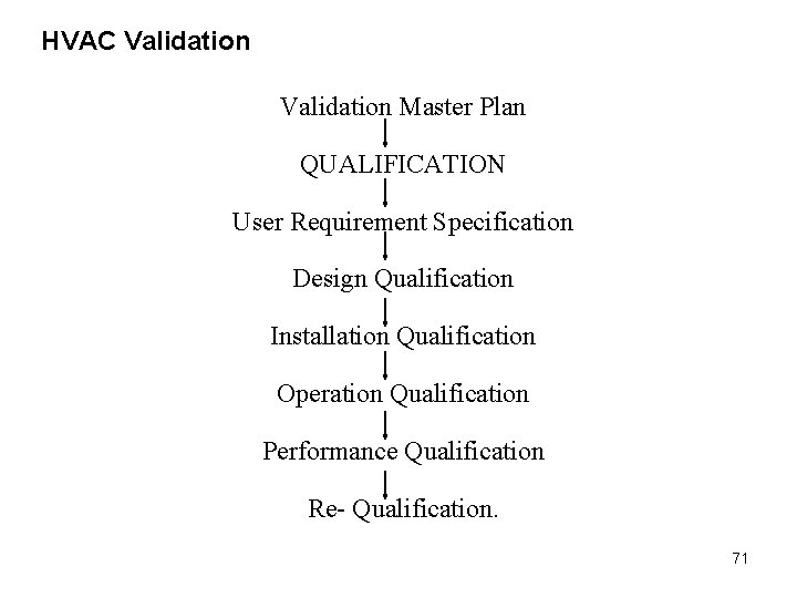
HVAC Validation Master Plan QUALIFICATION User Requirement Specification Design Qualification Installation Qualification Operation Qualification Performance Qualification Re- Qualification. 71
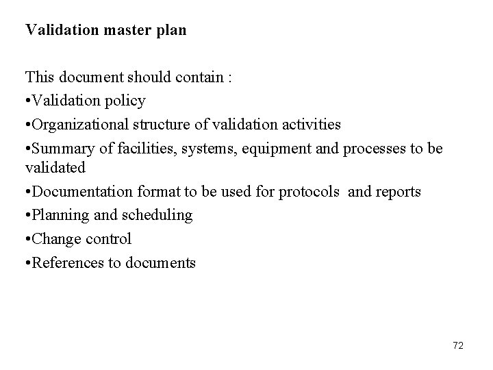
Validation master plan This document should contain : • Validation policy • Organizational structure of validation activities • Summary of facilities, systems, equipment and processes to be validated • Documentation format to be used for protocols and reports • Planning and scheduling • Change control • References to documents 72
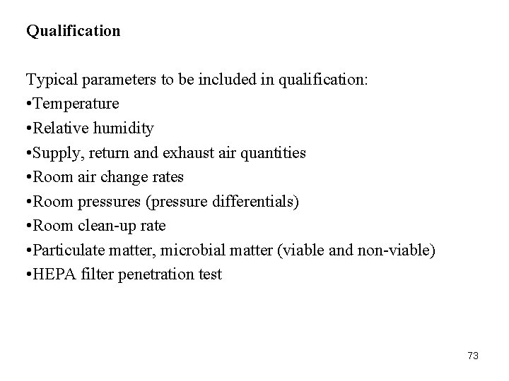
Qualification Typical parameters to be included in qualification: • Temperature • Relative humidity • Supply, return and exhaust air quantities • Room air change rates • Room pressures (pressure differentials) • Room clean-up rate • Particulate matter, microbial matter (viable and non-viable) • HEPA filter penetration test 73
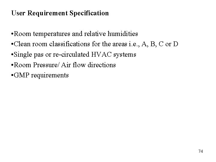
User Requirement Specification • Room temperatures and relative humidities • Clean room classifications for the areas i. e. , A, B, C or D • Single pas or re-circulated HVAC systems • Room Pressure/ Air flow directions • GMP requirements 74
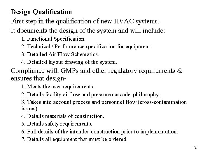
Design Qualification First step in the qualification of new HVAC systems. It documents the design of the system and will include: 1. Functional Specification. 2. Technical / Performance specification for equipment. 3. Detailed Air Flow Schematics. 4. Detailed layout drawing of the system. Compliance with GMPs and other regulatory requirements & ensures that design 1. Meets the user requirements. 2. Details facility airflow and pressure cascade philosophy. 3. Takes into account process and personnel flow (cross-contamination issues) 4. Details materials of construction. 5. Details safety requirements. 6. Full details of the intended construction prior to implementation. 7. Details all equipment that must be ordered. 75
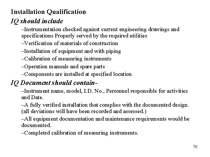
Installation Qualification IQ should include –Instrumentation checked against current engineering drawings and specifications Properly served by the required utilities –Verification of materials of construction –Installation of equipment and with piping –Calibration of measuring instruments –Operation manuals and spare parts –Components are installed at specified location IQ Document should contain–Instrument name, model, I. D. No. , Personnel responsible for activities and Date. –A fully verified installation that complies with the documented design. (all deviations will have been recorded and assessed. ) –All equipment documentation and maintenance requirements would be documented. –Completed calibration of measuring instruments. 76
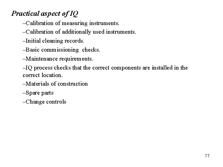
Practical aspect of IQ –Calibration of measuring instruments. –Calibration of additionally used instruments. –Initial cleaning records. –Basic commissioning checks. –Maintenance requirements. –IQ process checks that the correct components are installed in the correct location. –Materials of construction –Spare parts –Change controls 77
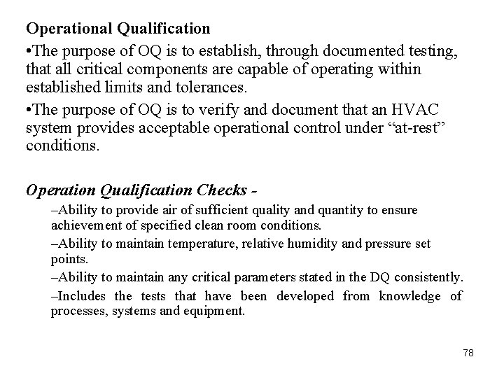
Operational Qualification • The purpose of OQ is to establish, through documented testing, that all critical components are capable of operating within established limits and tolerances. • The purpose of OQ is to verify and document that an HVAC system provides acceptable operational control under “at-rest” conditions. Operation Qualification Checks –Ability to provide air of sufficient quality and quantity to ensure achievement of specified clean room conditions. –Ability to maintain temperature, relative humidity and pressure set points. –Ability to maintain any critical parameters stated in the DQ consistently. –Includes the tests that have been developed from knowledge of processes, systems and equipment. 78
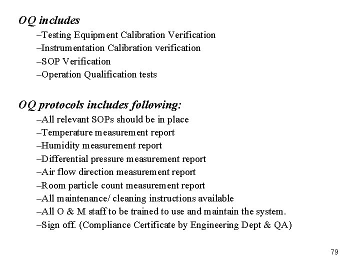
OQ includes –Testing Equipment Calibration Verification –Instrumentation Calibration verification –SOP Verification –Operation Qualification tests OQ protocols includes following: –All relevant SOPs should be in place –Temperature measurement report –Humidity measurement report –Differential pressure measurement report –Air flow direction measurement report –Room particle count measurement report –All maintenance/ cleaning instructions available –All O & M staff to be trained to use and maintain the system. –Sign off. (Compliance Certificate by Engineering Dept & QA) 79
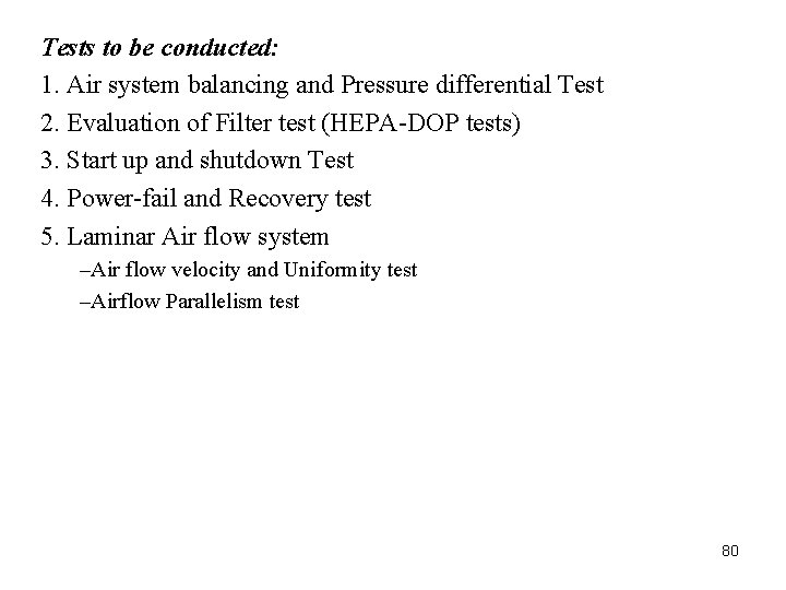
Tests to be conducted: 1. Air system balancing and Pressure differential Test 2. Evaluation of Filter test (HEPA-DOP tests) 3. Start up and shutdown Test 4. Power-fail and Recovery test 5. Laminar Air flow system –Air flow velocity and Uniformity test –Airflow Parallelism test 80
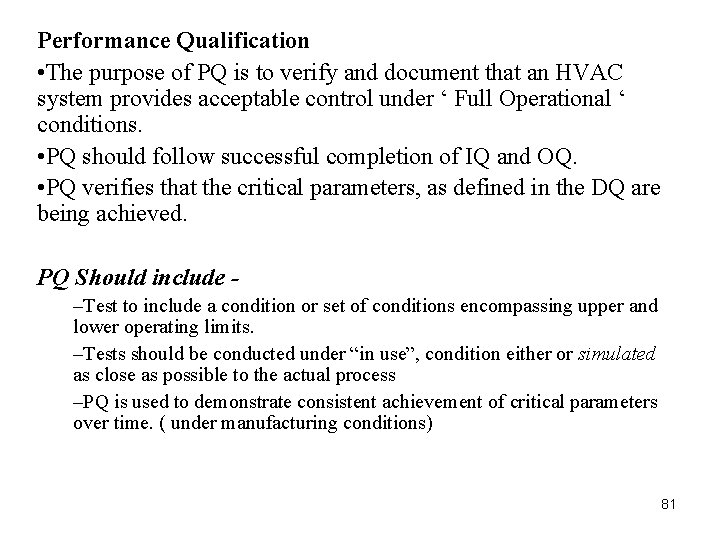
Performance Qualification • The purpose of PQ is to verify and document that an HVAC system provides acceptable control under ‘ Full Operational ‘ conditions. • PQ should follow successful completion of IQ and OQ. • PQ verifies that the critical parameters, as defined in the DQ are being achieved. PQ Should include –Test to include a condition or set of conditions encompassing upper and lower operating limits. –Tests should be conducted under “in use”, condition either or simulated as close as possible to the actual process –PQ is used to demonstrate consistent achievement of critical parameters over time. ( under manufacturing conditions) 81
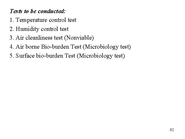
Tests to be conducted: 1. Temperature control test 2. Humidity control test 3. Air cleanliness test (Nonviable) 4. Air borne Bio-burden Test (Microbiology test) 5. Surface bio-burden Test (Microbiology test) 82
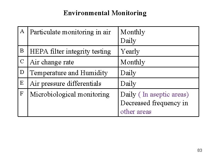
Environmental Monitoring A Particulate monitoring in air B HEPA filter integrity testing C Air change rate D Temperature and Humidity E Air pressure differentials F Microbiological monitoring Monthly Daily Yearly Monthly Daily ( In aseptic areas) Decreased frequency in other areas 83
Cleaning Validation • Cleaning involves removing an unwanted substance (contaminant) from the surface. • Cleaning Validation is the process of providing documented evidence that the cleaning methods employed within a facility consistently controls potential carryover of product (including intermediates and impurities), cleaning agents and extraneous material and also confirms a reliable cleaning procedure. • The Cleaning technique depends on the solubility of the drug and difficulty of cleaning. • Cleaning Validation is a mandatory requirement by the regulatory agencies and the industry itself. 84
Why to validate cleaning process? • To Protect product integrity and to avoid cross contamination for internal control and compliance. • To reuse the equipments and make the process more cost effective. • To combat the regulatory authorities (FDA, USFDA, c. GMP). • To increase Equipment Utilization. • For multiproduct Equipments. • To assure maximum cleaning without affecting the safety or efficacy of the next product to be manufactured in the cleaned equipment. Levels of cleaning –Level 0 –Level 1 –Level 2 85
Level 0 cleaning (Batch to Batch): • It is an in- campaign batch to batch changeover requiring no validation. • It can be of two types: • Done between intermediate steps in the same manufacturing process. Eg. Step B is performed immediately after Step A for the same product line. • Done between the steps in the manufacturing processes of 2 batches of the same product. Eg. For a given equipment, Step A of the first batch is to be followed by the manufacturing of Step A of second batch. 86
Level 1 cleaning (Product to Product): It is performed when cleaning after an intermediate or final product step of one product followed by the production of an intermediate step of the other product. Eg. For a given equipment, Step A of drug A followed by step A of drug B. Level 2 cleaning (Product to Product): It is performed when cleaning after an intermediate or final product step of one product followed by the production of final step of the other product. Eg. Step A of drug A followed by last step of drug B. 87
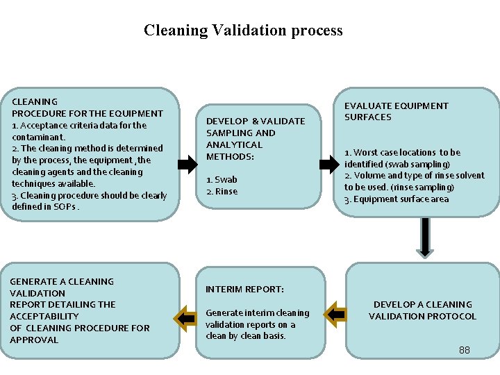
Cleaning Validation process CLEANING PROCEDURE FOR THE EQUIPMENT 1. Acceptance criteria data for the contaminant. 2. The cleaning method is determined by the process, the equipment , the cleaning agents and the cleaning techniques available. 3. Cleaning procedure should be clearly defined in SOPs. GENERATE A CLEANING VALIDATION REPORT DETAILING THE ACCEPTABILITY OF CLEANING PROCEDURE FOR APPROVAL Stage 1 DEVELOP & VALIDATE SAMPLING AND ANALYTICAL METHODS: 1. Swab 2. Rinse EVALUATE EQUIPMENT SURFACES 1. Worst case locations to be identified (swab sampling) 2. Volume and type of rinse solvent to be used. (rinse sampling) 3. Equipment surface area INTERIM REPORT: Generate interim cleaning validation reports on a clean by clean basis. DEVELOP A CLEANING VALIDATION PROTOCOL 88
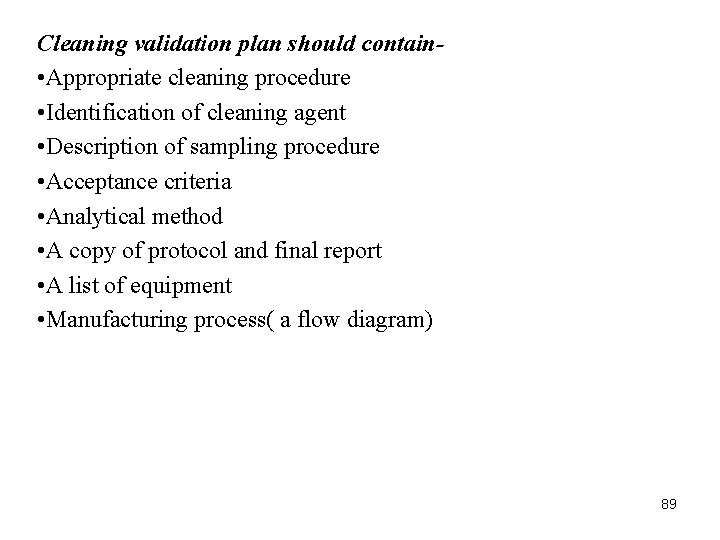
Cleaning validation plan should contain • Appropriate cleaning procedure • Identification of cleaning agent • Description of sampling procedure • Acceptance criteria • Analytical method • A copy of protocol and final report • A list of equipment • Manufacturing process( a flow diagram) 89
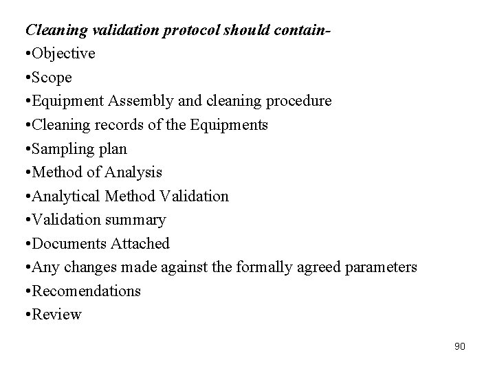
Cleaning validation protocol should contain • Objective • Scope • Equipment Assembly and cleaning procedure • Cleaning records of the Equipments • Sampling plan • Method of Analysis • Analytical Method Validation • Validation summary • Documents Attached • Any changes made against the formally agreed parameters • Recomendations • Review 90
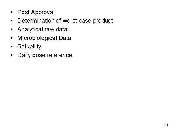
• • • Post Approval Determination of worst case product Analytical raw data Microbiological Data Solubility Daily dose reference 91
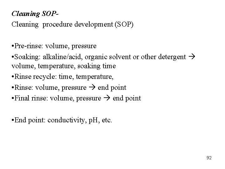
Cleaning SOPCleaning procedure development (SOP) • Pre-rinse: volume, pressure • Soaking: alkaline/acid, organic solvent or other detergent volume, temperature, soaking time • Rinse recycle: time, temperature, • Rinse: volume, pressure end point • Final rinse: volume, pressure end point • End point: conductivity, p. H, etc. 92
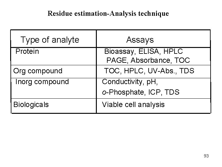
Residue estimation-Analysis technique Type of analyte Protein Org compound Inorg compound Biologicals Assays Bioassay, ELISA, HPLC PAGE, Absorbance, TOC, HPLC, UV-Abs. , TDS Conductivity, p. H, o-Phosphate, ICP, TDS Viable cell analysis 93
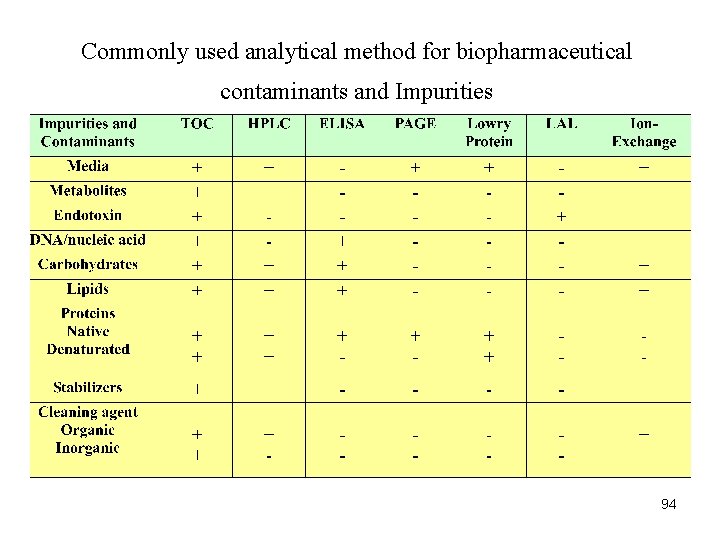
Commonly used analytical method for biopharmaceutical contaminants and Impurities 94
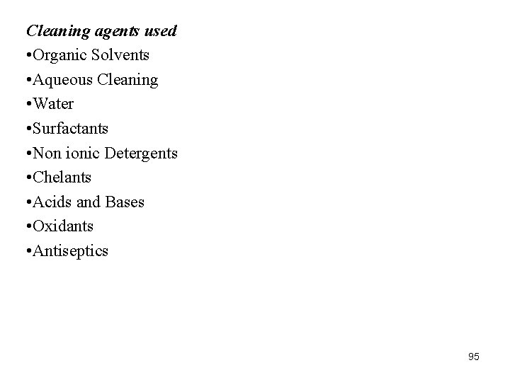
Cleaning agents used • Organic Solvents • Aqueous Cleaning • Water • Surfactants • Non ionic Detergents • Chelants • Acids and Bases • Oxidants • Antiseptics 95
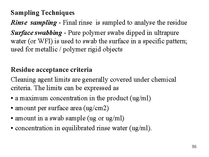
Sampling Techniques Rinse sampling - Final rinse is sampled to analyse the residue Surface swabbing - Pure polymer swabs dipped in ultrapure water (or WFI) is used to swab the surface in a specific pattern; used for metallic / polymer rigid objects Residue acceptance criteria Cleaning agent limits are generally covered under chemical criteria. The limits can be expressed as • a maximum concentration in the product (ug/ml) • amount per surface area (ug/cm 2) • amount in a swab sample (ug or ug/ml) • concentration in equilibrated rinse water (ug/ml). 96
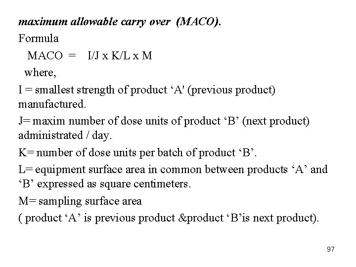
maximum allowable carry over (MACO). Formula MACO = I/J x K/L x M where, I = smallest strength of product ‘A' (previous product) manufactured. J= maxim number of dose units of product ‘B’ (next product) administrated / day. K= number of dose units per batch of product ‘B’. L= equipment surface area in common between products ‘A’ and ‘B’ expressed as square centimeters. M= sampling surface area ( product ‘A’ is previous product &product ‘B’is next product). 97
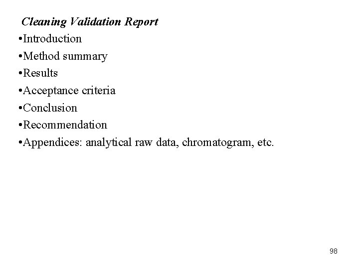
Cleaning Validation Report • Introduction • Method summary • Results • Acceptance criteria • Conclusion • Recommendation • Appendices: analytical raw data, chromatogram, etc. 98
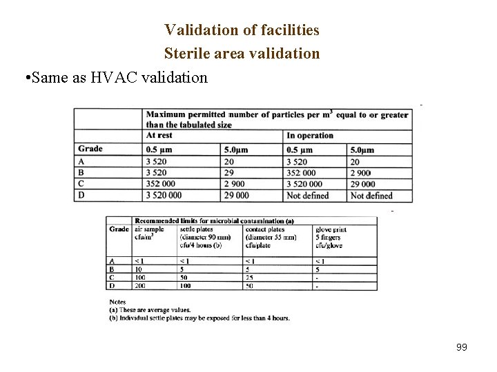
Validation of facilities Sterile area validation • Same as HVAC validation 99
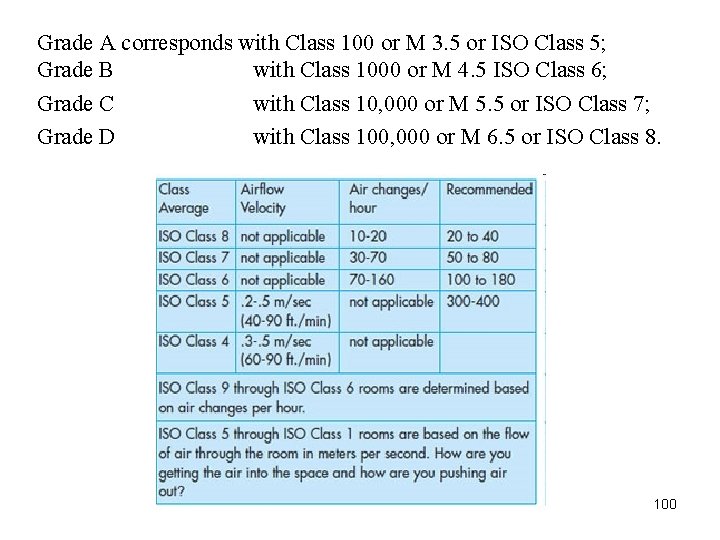
Grade A corresponds with Class 100 or M 3. 5 or ISO Class 5; Grade B with Class 1000 or M 4. 5 ISO Class 6; Grade C with Class 10, 000 or M 5. 5 or ISO Class 7; Grade D with Class 100, 000 or M 6. 5 or ISO Class 8. 100
Validation of facilities Non-sterile area validation • Same as sterile area, with no HEPA considerations 101
Statistical Process Control (SPC) • monitoring production process to detect and prevent poor quality • tool for identifying problems in order to make improvements • contributes to the TQM goal of continuous improvements Quality Measures: Attributes and Variables Attribute • a product characteristic that can be evaluated with a discrete response good – bad; yes - no Variable measure • a product characteristic that is continuous and can be measured weight - length 102
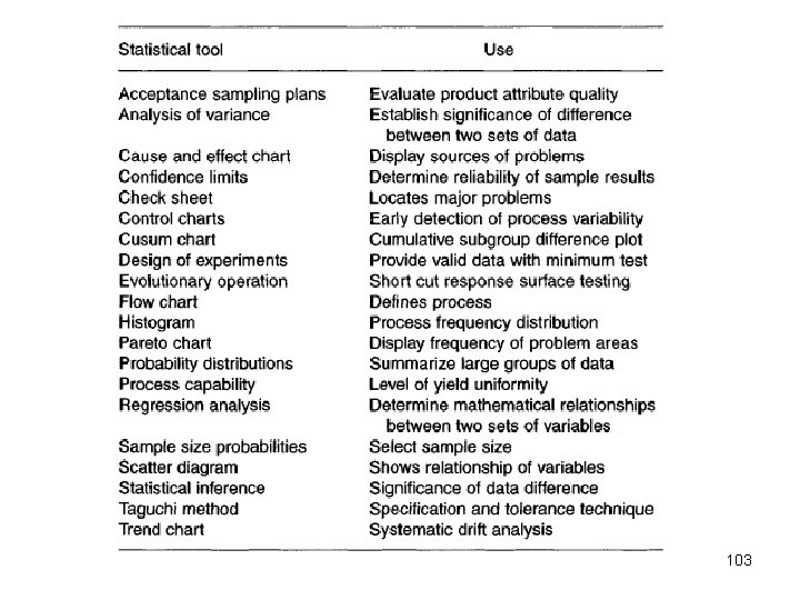
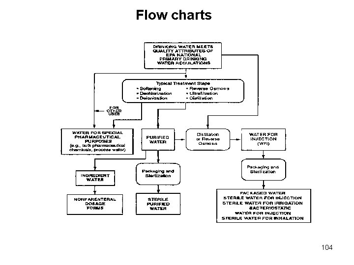
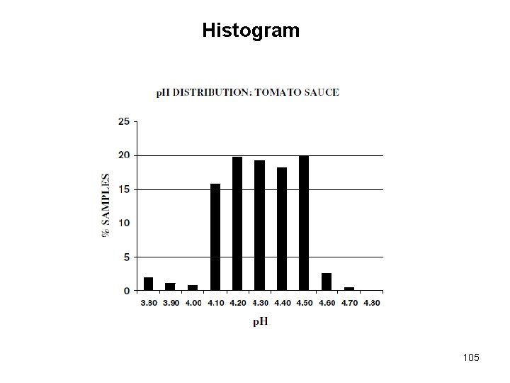
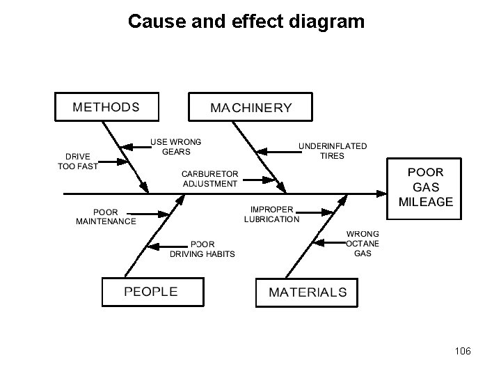
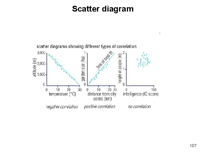
103
Flow charts 104
Histogram 105
Cause and effect diagram 106
Scatter diagram 107
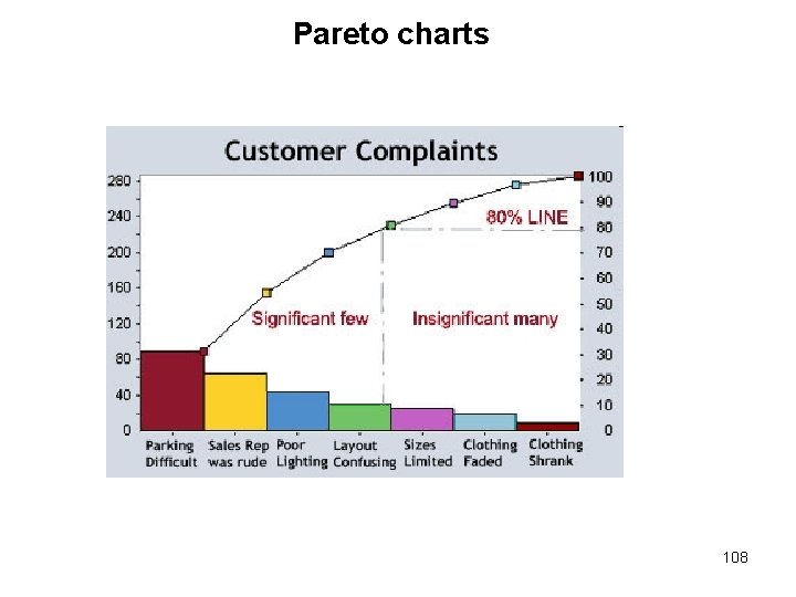
Pareto charts 108
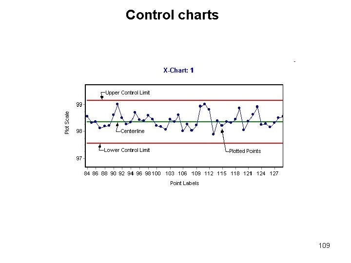
Control charts 109
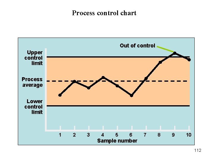
Control charts • Constructed from historical data, the purpose of control charts is to help distinguish between natural variations and variations due to assignable causes • A graph that establishes control limits of a process • Control limits –upper and lower bands of a control chart Types of charts • Attributes –p-chart –c-chart • Variables –mean (x bar – chart) –range (R-chart) 110
Where to use control charts? • Process has a tendency to go out of control • Process is particularly harmful and costly if it goes out of control Examples –at the beginning of a process because it is a waste of time and money to begin production process with bad supplies –before a costly or irreversible point, after which product is difficult to rework or correct –before and after assembly or painting operations that might cover defects –before the outgoing final product or service is delivered 111
Process control chart Out of control Upper control limit Process average Lower control limit 1 2 3 4 5 6 7 8 9 10 Sample number 112
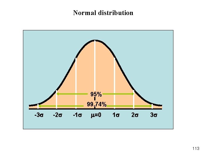
Normal distribution 95% 99. 74% -3 -2 -1 =0 1 2 3 113
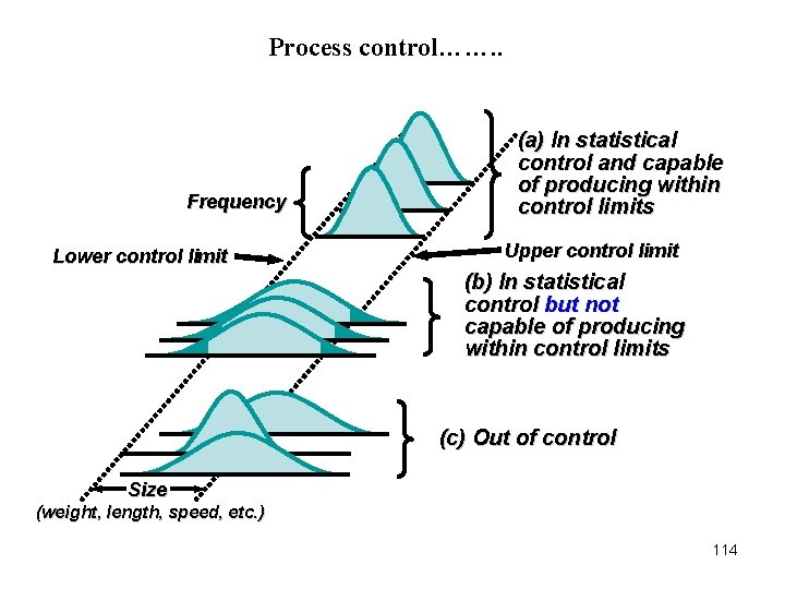
Process control……. . Frequency Lower control limit (a) In statistical control and capable of producing within control limits Upper control limit (b) In statistical control but not capable of producing within control limits (c) Out of control Size (weight, length, speed, etc. ) 114
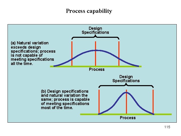
Process capability Design Specifications (a) Natural variation exceeds design specifications; process is not capable of meeting specifications all the time. Process Design Specifications (b) Design specifications and natural variation the same; process is capable of meeting specifications most of the time. Process 115
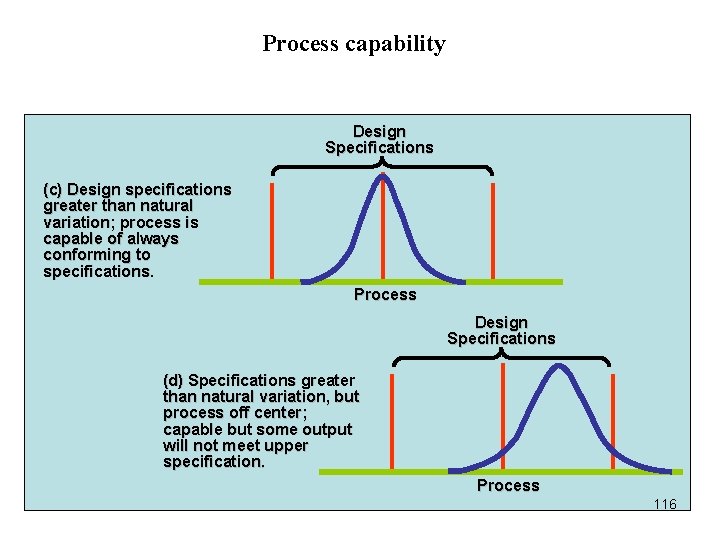
Process capability Design Specifications (c) Design specifications greater than natural variation; process is capable of always conforming to specifications. Process Design Specifications (d) Specifications greater than natural variation, but process off center; capable but some output will not meet upper specification. Process 116
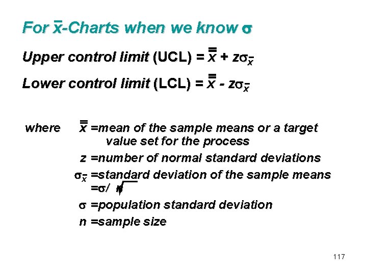
For x-Charts when we know Upper control limit (UCL) = x + z x Lower control limit (LCL) = x - z x where x =mean of the sample means or a target value set for the process z =number of normal standard deviations x =standard deviation of the sample means = / n =population standard deviation n =sample size 117
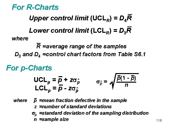
For R-Charts Upper control limit (UCLR) = D 4 R where Lower control limit (LCLR) = D 3 R R =average range of the samples D 3 and D 4 =control chart factors from Table S 6. 1 For p-Charts UCLp = p + z p^ LCLp = p - z p^ where p z p^ n p = ^ p(1 - p) n =mean fraction defective in the sample =number of standard deviations =standard deviation of the sampling distribution =sample size 118
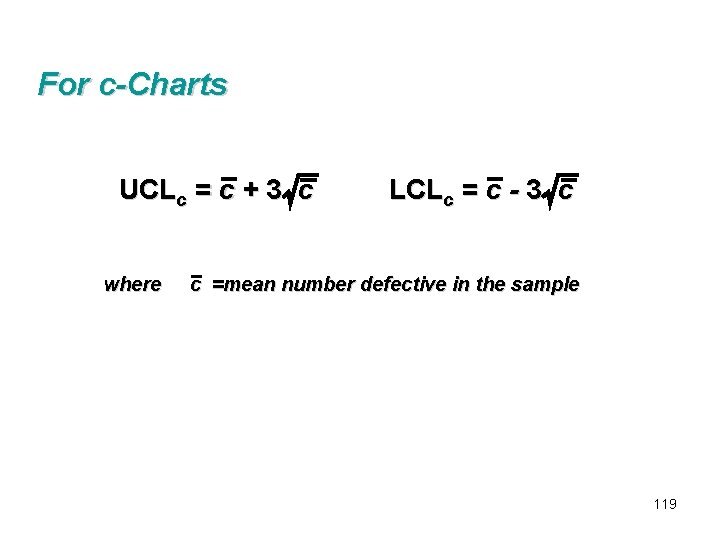
For c-Charts UCLc = c + 3 c where LCLc = c - 3 c c =mean number defective in the sample 119
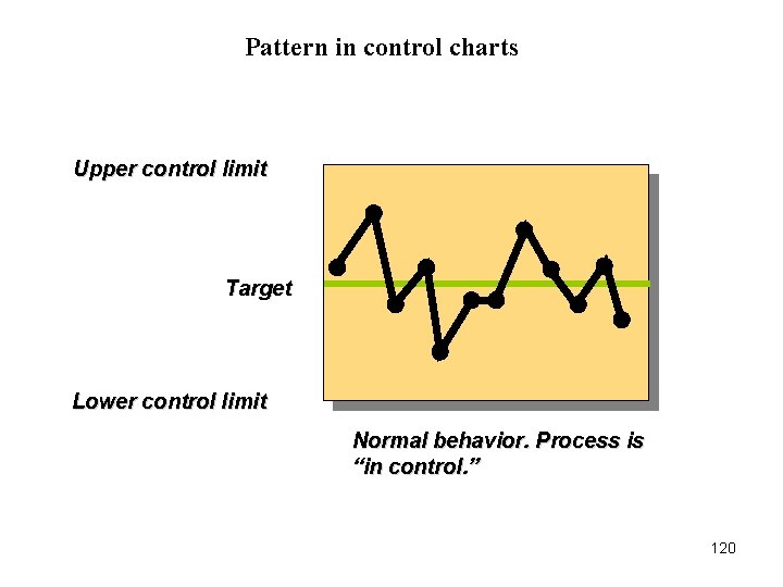
Pattern in control charts Upper control limit Target Lower control limit Normal behavior. Process is “in control. ” 120
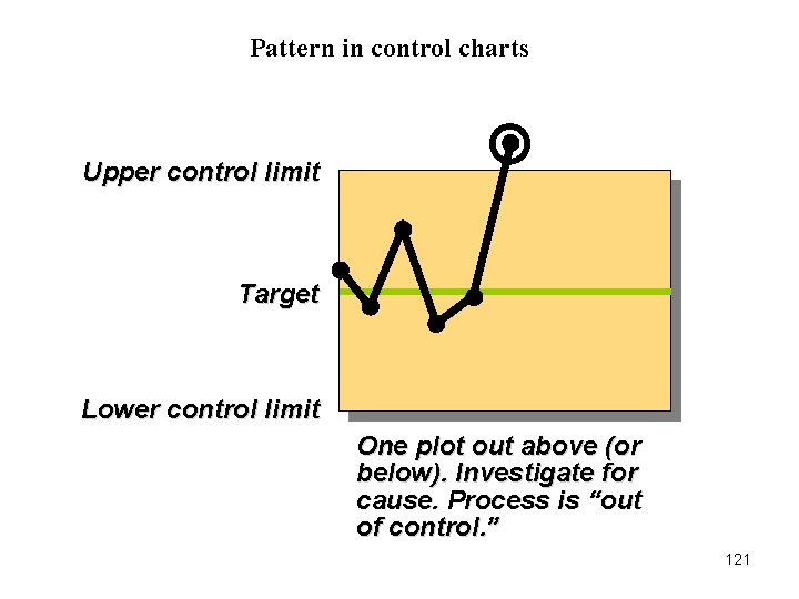
Pattern in control charts Upper control limit Target Lower control limit One plot out above (or below). Investigate for cause. Process is “out of control. ” 121
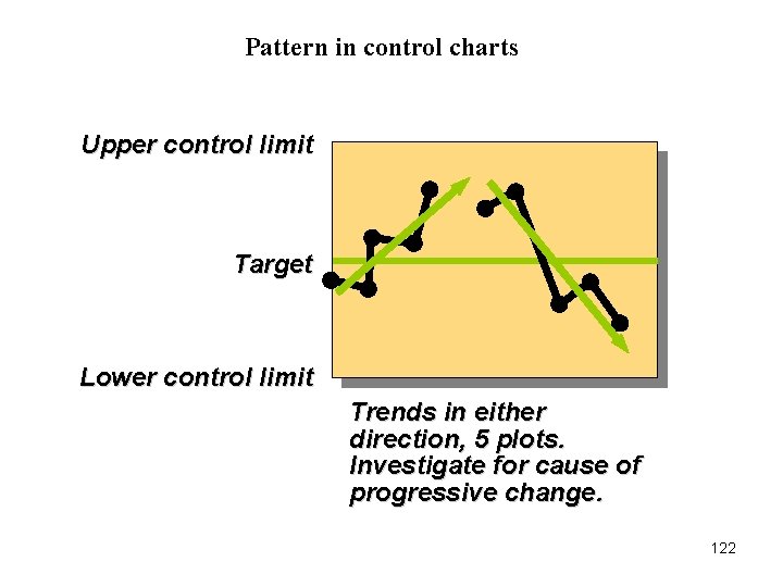
Pattern in control charts Upper control limit Target Lower control limit Trends in either direction, 5 plots. Investigate for cause of progressive change. 122
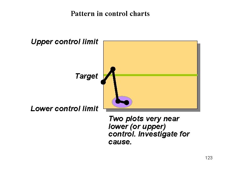
Pattern in control charts Upper control limit Target Lower control limit Two plots very near lower (or upper) control. Investigate for cause. 123
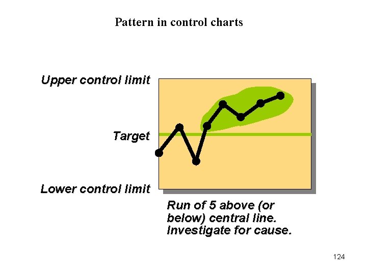
Pattern in control charts Upper control limit Target Lower control limit Run of 5 above (or below) central line. Investigate for cause. 124
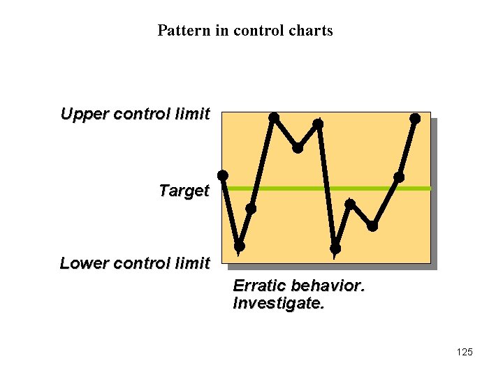
Pattern in control charts Upper control limit Target Lower control limit Erratic behavior. Investigate. 125
Which control chart to use Variables Data • Using an x-chart and R-chart: –Observations are variables –Collect 20 - 25 samples of n = 4, or n = 5, or more, each from a stable process and compute the mean for the x-chart and range for the R-chart –Track samples of n observations each Attribute data • Using the p-chart: –Observations are attributes that can be categorized in two states –We deal with fraction, proportion, or percent defectives –Have several samples, each with many observations • Using a c-Chart: –Observations are attributes whose defects per unit of output can be counted –The number counted is often a small part of the possible occurrences –Defects such as number of blemishes on a desk, number of typos in a page of text, flaws in a bolt of cloth 126
THANK YOU 127