Energy and Energy Types Energy is the capacity


- Slides: 108
Energy and Energy Types
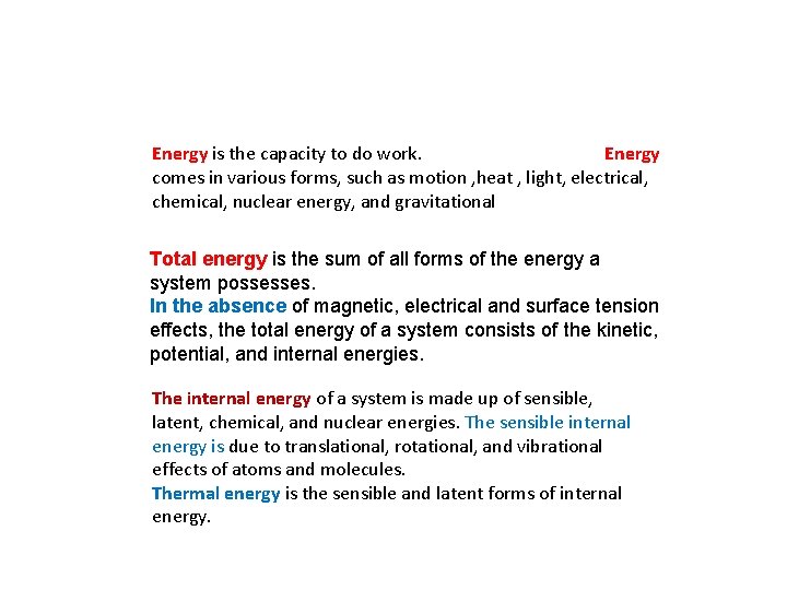
Energy is the capacity to do work. Energy comes in various forms, such as motion , heat , light, electrical, chemical, nuclear energy, and gravitational Total energy is the sum of all forms of the energy a system possesses. In the absence of magnetic, electrical and surface tension effects, the total energy of a system consists of the kinetic, potential, and internal energies. The internal energy of a system is made up of sensible, latent, chemical, and nuclear energies. The sensible internal energy is due to translational, rotational, and vibrational effects of atoms and molecules. Thermal energy is the sensible and latent forms of internal energy.
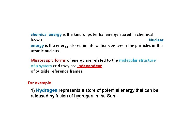
chemical energy is the kind of potential energy stored in chemical bonds. Nuclear energy is the energy stored in interactions between the particles in the atomic nucleus. Microscopic forms of energy are related to the molecular structure of a system and they are independent of outside reference frames. For example 1) Hydrogen represents a store of potential energy that can be released by fusion of hydrogen in the Sun.
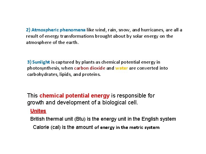
2) Atmospheric phenomena like wind, rain, snow, and hurricanes, are all a result of energy transformations brought about by solar energy on the atmosphere of the earth. 3) Sunlight is captured by plants as chemical potential energy in photosynthesis, when carbon dioxide and water are converted into carbohydrates, lipids, and proteins. This chemical potential energy is responsible for growth and development of a biological cell. Unites British thermal unit (Btu) is the energy unit in the English system Calorie (cal) is the amount of energy in the metric system
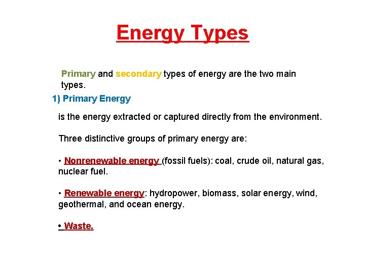
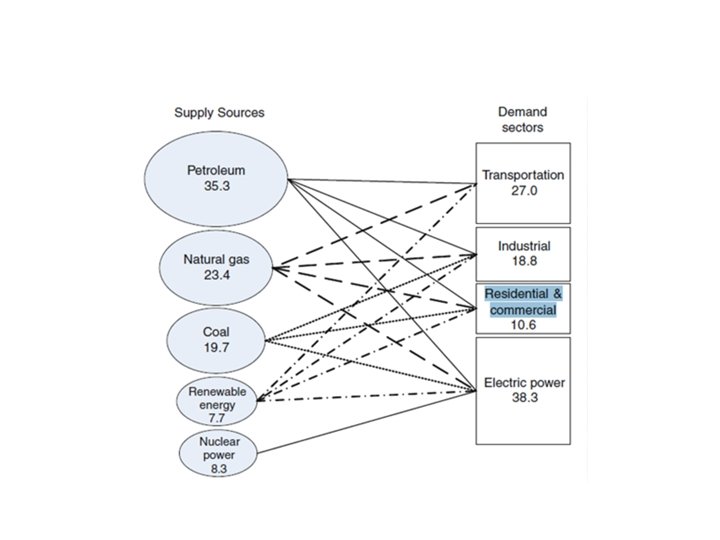
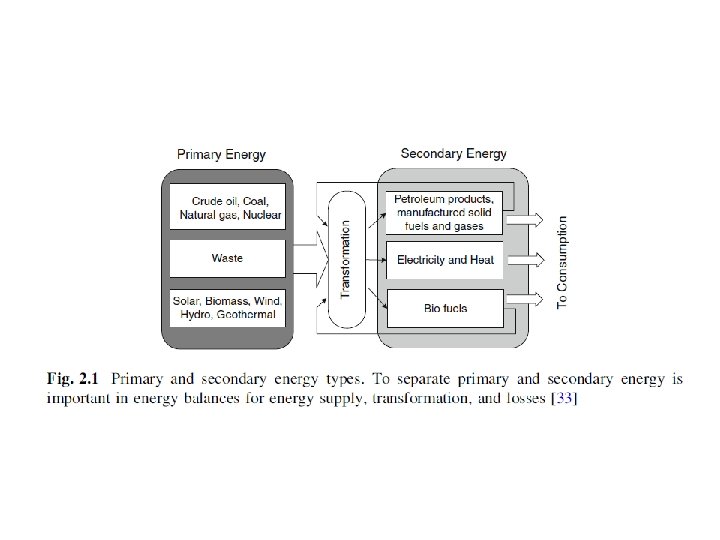
Energy Types Primary and secondary types of energy are the two main types. 1) Primary Energy is the energy extracted or captured directly from the environment. Three distinctive groups of primary energy are: • Nonrenewable energy (fossil fuels): coal, crude oil, natural gas, nuclear fuel. • Renewable energy: hydropower, biomass, solar energy, wind, geothermal, and ocean energy. • Waste.
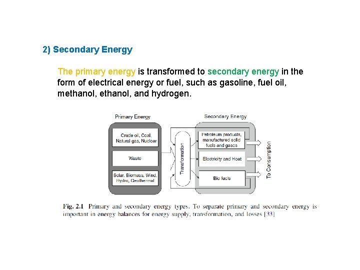
2) Secondary Energy The primary energy is transformed to secondary energy in the form of electrical energy or fuel, such as gasoline, fuel oil, methanol, and hydrogen.
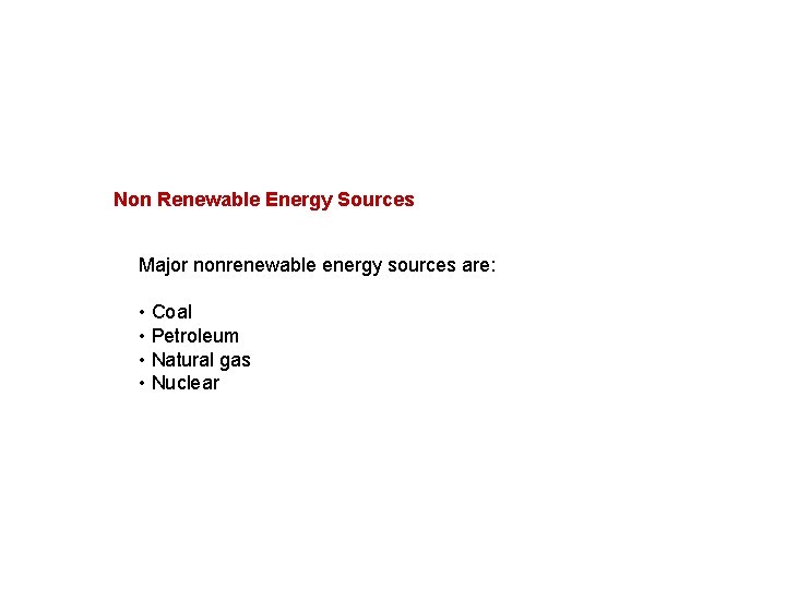
Non Renewable Energy Sources Major nonrenewable energy sources are: • Coal • Petroleum • Natural gas • Nuclear
1) Coals are sedimentary rocks containing combustible and incombustible matters as well as water. The poorest lignite has less than 50% carbon and an energy density lower than wood. Anthracites have more than 90% carbon. It is very hard and shiny and the ultimate maturation. It creates a steady and clean flame and is preferred for domestic heating. Furthermore it burns longer with more heat than the other types. Bituminous coals mostly between 70 and 75%. Bituminous coal ignites easily and burns with a relatively long flame. If improperly fired, bituminous coal is characterized with excess smoke and soot. Anthracite.
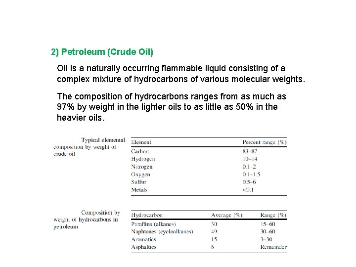
2) Petroleum (Crude Oil) Oil is a naturally occurring flammable liquid consisting of a complex mixture of hydrocarbons of various molecular weights. The composition of hydrocarbons ranges from as much as 97% by weight in the lighter oils to as little as 50% in the heavier oils.
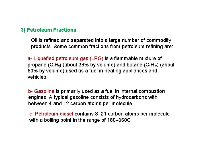
3) Petroleum Fractions Oil is refined and separated into a large number of commodity products. Some common fractions from petroleum refining are: a- Liquefied petroleum gas (LPG) is a flammable mixture of propane (C 3 H 8) (about 38% by volume) and butane (C 4 H 10) (about 60% by volume). used as a fuel in heating appliances and vehicles. b- Gasoline is primarily used as a fuel in internal combustion engines. A typical gasoline consists of hydrocarbons with between 4 and 12 carbon atoms per molecule. c- Petroleum diesel contains 8– 21 carbon atoms per molecule with a boiling point in the range of 180– 360 C
d- Kerosene is a thin, clear liquid formed containing between 6 and 16 carbon atoms per molecule. e- Jet fuel is a type of aviation fuel designed for use in aircraft powered by gas turbine engines. f- Fuel oil is made of long hydrocarbon chains, particularly alkanes, cycloalkanes, and aromatics and heavier than gasoline and It is classified into six classes, numbered 1 through 6, according to its boiling point, composition, and purpose. 4) Natural Gas is a naturally occurring mixture, consisting mainly of methane. Natural gas provides 23% of all energy consumed in the world. a- liquefied natural gas The volume of the liquid is approximately 1/600 of the gaseous volume at atmospheric conditions.
5) Nuclear Energy plants produce electricity through the fission of nuclear fuel, such as uranium, so they do not pollute the air with harmful gases. Nuclear fission is a nuclear reaction in which the nucleus of an atom splits into smaller parts, often producing free neutrons and photons in the form of gamma rays and releasing large amounts of energy.
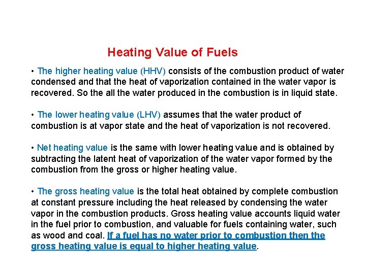
Heating Value of Fuels • The higher heating value (HHV) consists of the combustion product of water condensed and that the heat of vaporization contained in the water vapor is recovered. So the all the water produced in the combustion is in liquid state. • The lower heating value (LHV) assumes that the water product of combustion is at vapor state and the heat of vaporization is not recovered. • Net heating value is the same with lower heating value and is obtained by subtracting the latent heat of vaporization of the water vapor formed by the combustion from the gross or higher heating value. • The gross heating value is the total heat obtained by complete combustion at constant pressure including the heat released by condensing the water vapor in the combustion products. Gross heating value accounts liquid water in the fuel prior to combustion, and valuable for fuels containing water, such as wood and coal. If a fuel has no water prior to combustion the gross heating value is equal to higher heating value.
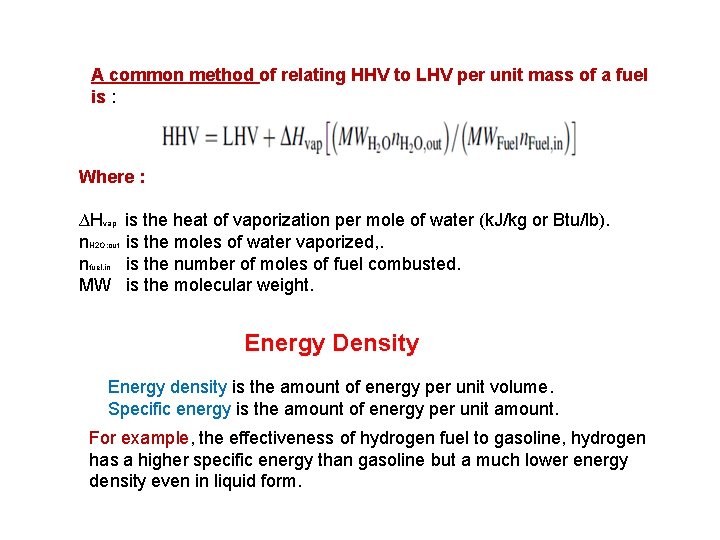
A common method of relating HHV to LHV per unit mass of a fuel is : Where : ∆Hvap n. H 2 O; out nfuel, in MW is the heat of vaporization per mole of water (k. J/kg or Btu/lb). is the moles of water vaporized, . is the number of moles of fuel combusted. is the molecular weight. Energy Density Energy density is the amount of energy per unit volume. Specific energy is the amount of energy per unit amount. For example, the effectiveness of hydrogen fuel to gasoline, hydrogen has a higher specific energy than gasoline but a much lower energy density even in liquid form.
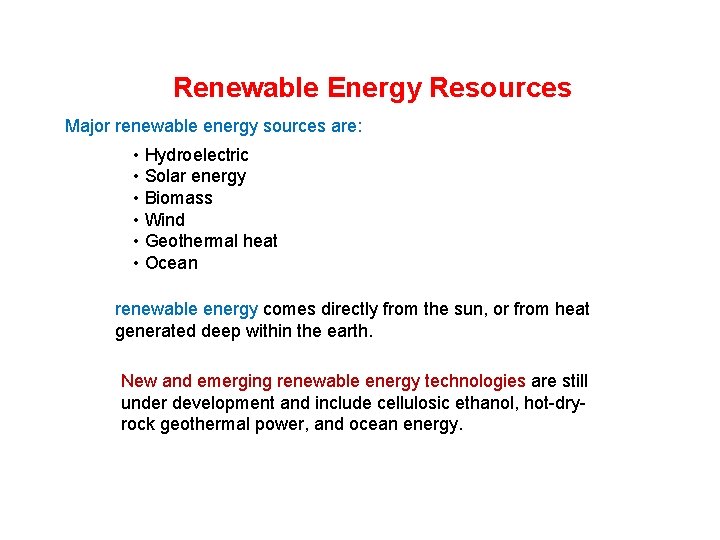
Renewable Energy Resources Major renewable energy sources are: • Hydroelectric • Solar energy • Biomass • Wind • Geothermal heat • Ocean renewable energy comes directly from the sun, or from heat generated deep within the earth. New and emerging renewable energy technologies are still under development and include cellulosic ethanol, hot-dryrock geothermal power, and ocean energy.
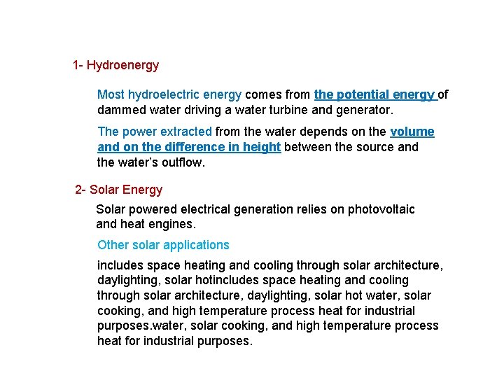
1 - Hydroenergy Most hydroelectric energy comes from the potential energy of dammed water driving a water turbine and generator. The power extracted from the water depends on the volume and on the difference in height between the source and the water’s outflow. 2 - Solar Energy Solar powered electrical generation relies on photovoltaic and heat engines. Other solar applications includes space heating and cooling through solar architecture, daylighting, solar hot water, solar cooking, and high temperature process heat for industrial purposes.
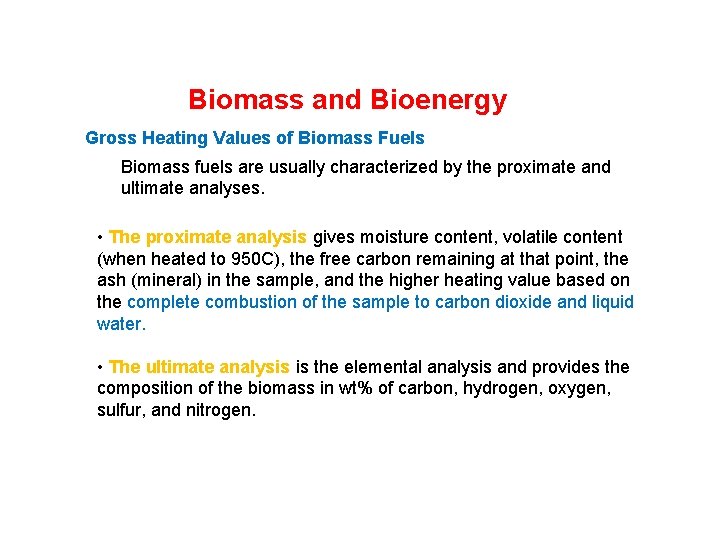
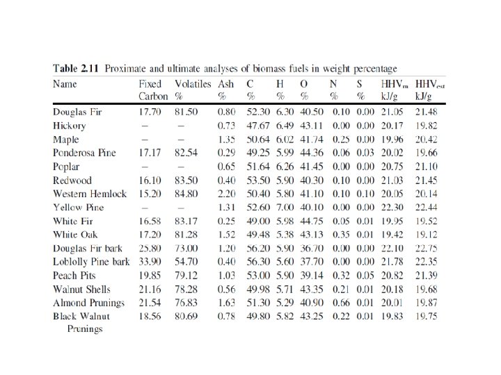
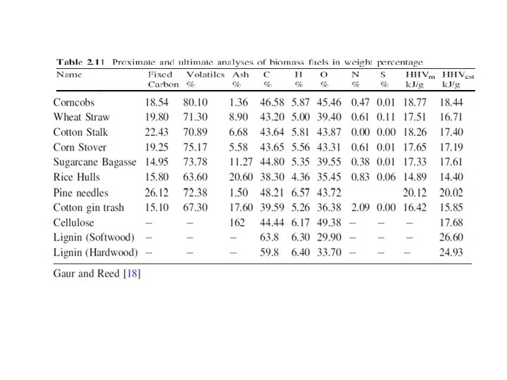
Biomass and Bioenergy Gross Heating Values of Biomass Fuels Biomass fuels are usually characterized by the proximate and ultimate analyses. • The proximate analysis gives moisture content, volatile content (when heated to 950 C), the free carbon remaining at that point, the ash (mineral) in the sample, and the higher heating value based on the complete combustion of the sample to carbon dioxide and liquid water. • The ultimate analysis is the elemental analysis and provides the composition of the biomass in wt% of carbon, hydrogen, oxygen, sulfur, and nitrogen.
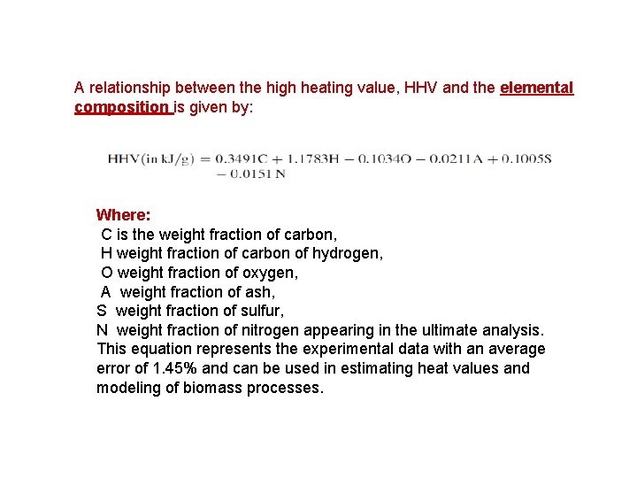
A relationship between the high heating value, HHV and the elemental composition is given by: Where: C is the weight fraction of carbon, H weight fraction of carbon of hydrogen, O weight fraction of oxygen, A weight fraction of ash, S weight fraction of sulfur, N weight fraction of nitrogen appearing in the ultimate analysis. This equation represents the experimental data with an average error of 1. 45% and can be used in estimating heat values and modeling of biomass processes.
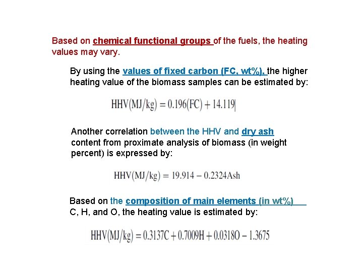
Based on chemical functional groups of the fuels, the heating values may vary. By using the values of fixed carbon (FC, wt%), the higher heating value of the biomass samples can be estimated by: Another correlation between the HHV and dry ash content from proximate analysis of biomass (in weight percent) is expressed by: Based on the composition of main elements (in wt%) C, H, and O, the heating value is estimated by:
BIO ENERGY Part(1)
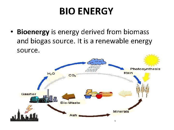
BIO ENERGY • Bioenergy is energy derived from biomass and biogas source. It is a renewable energy source.
BIOMASS • Biomassis organic matter from plants, micro- -organism grown on land water and their derivatives. The energy obtain from biomass is also called the biomass energy. It is a renew- -able energy source. Because organic matter generated everyday. Coal, petroleum, natural gas are not come in biomass category because they produce from dead, burried biomass under high pressure and temperature during several millions of year.
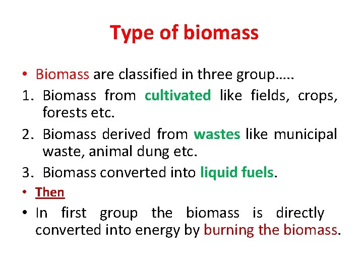
Type of biomass • Biomass are classified in three group…. . 1. Biomass from cultivated like fields, crops, forests etc. 2. Biomass derived from wastes like municipal waste, animal dung etc. 3. Biomass converted into liquid fuels. • Then • In first group the biomass is directly converted into energy by burning the biomass.
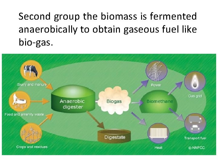
Second group the biomass is fermented anaerobically to obtain gaseous fuel like bio-gas.
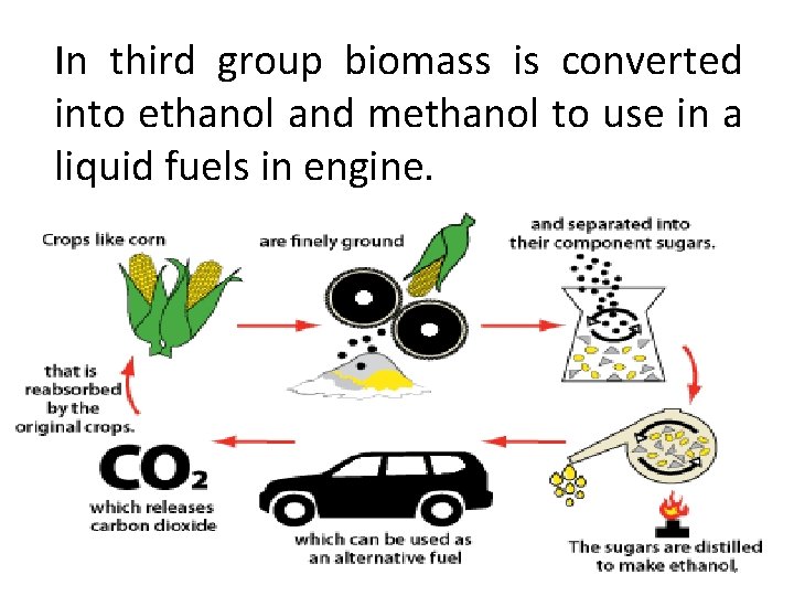
In third group biomass is converted into ethanol and methanol to use in a liquid fuels in engine.
Biomass power generation technologies PART (2)
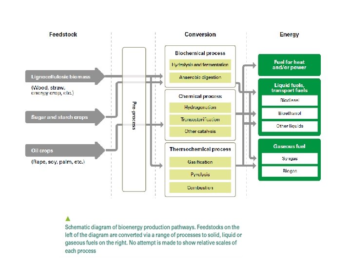
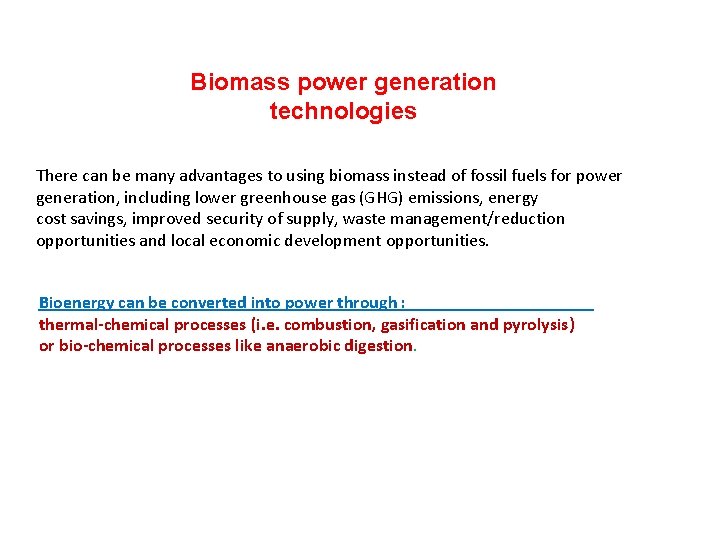
Biomass power generation technologies There can be many advantages to using biomass instead of fossil fuels for power generation, including lower greenhouse gas (GHG) emissions, energy cost savings, improved security of supply, waste management/reduction opportunities and local economic development opportunities. Thermo-Chemical Process Bioenergy can be converted into power through : thermal-chemical processes (i. e. combustion, gasification and pyrolysis) or bio-chemical processes like anaerobic digestion.
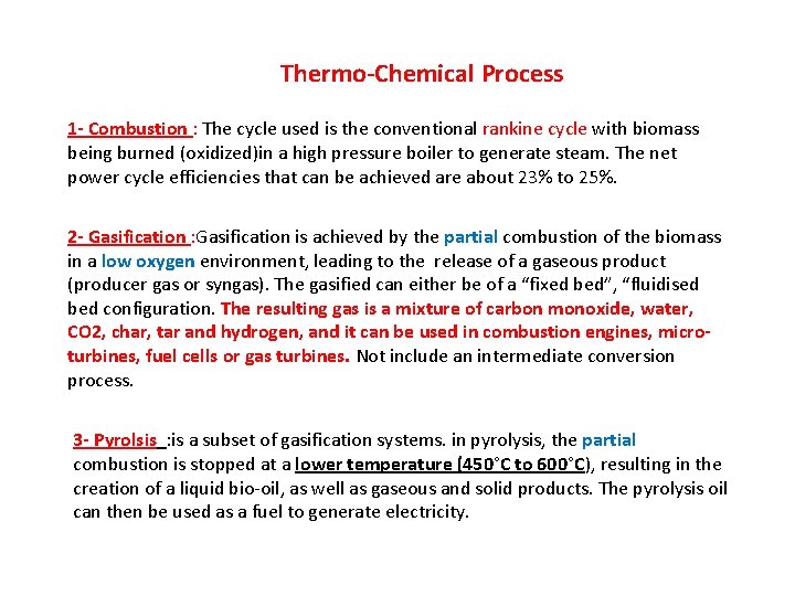
Thermo-Chemical Process 1 - Combustion : The cycle used is the conventional rankine cycle with biomass being burned (oxidized)in a high pressure boiler to generate steam. The net power cycle efficiencies that can be achieved are about 23% to 25%. 2 - Gasification : Gasification is achieved by the partial combustion of the biomass in a low oxygen environment, leading to the release of a gaseous product (producer gas or syngas). The gasified can either be of a “fixed bed”, “fluidised bed configuration. The resulting gas is a mixture of carbon monoxide, water, CO 2, char, tar and hydrogen, and it can be used in combustion engines, microturbines, fuel cells or gas turbines. Not include an intermediate conversion process. 3 - Pyrolsis : is a subset of gasification systems. in pyrolysis, the partial combustion is stopped at a lower temperature (450°C to 600°C), resulting in the creation of a liquid bio-oil, as well as gaseous and solid products. The pyrolysis oil can then be used as a fuel to generate electricity.
Bio-Chemical Process Anaerobic Digestion : anaerobic digestion is a process which takes place in almost any biological material that. The resulting gas consists mainly of methane and carbon dioxide and is referred to as biogas. The biogas can be used, after clean-up, in internal combustion engines, micro-turbines, gas turbines, fuel cells and starling engines or it can be upgraded to biomethane for distribution. BIOMASS COMBUSTION TECHNOLOGIES Around the globe, over 90% of the biomass that is used for energy purposes goes through the combustion route. There are two main components of a combustion–based biomass plant: 1) the biomass-fired boiler that produces steam; and 2) the steam turbine, which is then used to generate electricity.
The two most common forms of boilers are stoker and fluidized bed. These can be fuelled entirely by biomass or can be co-fired with a combination of biomass and coal or other solid fuels. BOILER TYPES Stoker boilers : burn fuel on a grate, producing hot flue gases that are then used to produce steam. There are two general types of stokers. Underfeed boilers supply both the fuel and the air from under the grate. Overfeed boilers supply the fuel from above the grate and the air from below. Fluidised boilers : suspend fuels on upward blowing jets of air during the combustion process. They are categorized as either atmospheric or pressurized units. Atmospheric fluidized boilers are further divided into bubbling-bed and circulating-bed units. Difference between bubbling-bed and circulating-bed boilers is the fluidisation velocity (higher for circulating). atmospheric-bubbling fluidised boilers are more commonly used when the fuel is biomass.
The steam produced in the boilers is injected into steam turbines. There are three major types of turbines with each one having its own specific characteristics. Major types of turbines: 1 - Condensing Steam Turbine. : designed to obtain the maximum amount of shaft work out of a given steam input. 2 - Extraction Steam Turbine : it is designed to allow steam to be extracted from the turbine at intermediate pressures in the middle part of the turbine. This is desirable for combined heat and power systems. This type of turbine offers a high flexibility of operation but at the expense of electrical efficiency. 3 - Backpressure Steam Turbine : design is mostly used when a constant supply of heat is required. Backpressure turbines discharge steam at high temperatures and pressures. Backpressure turbine will produce lower amounts of shaft power and have a lower electrical efficiency. Used in Brazil in the sugar cane industry (cheaper )
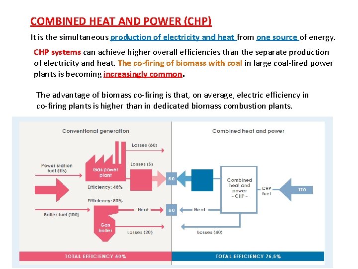
COMBINED HEAT AND POWER (CHP) It is the simultaneous production of electricity and heat from one source of energy. CHP systems can achieve higher overall efficiencies than the separate production of electricity and heat. The co-firing of biomass with coal in large coal-fired power plants is becoming increasingly common. The advantage of biomass co-firing is that, on average, electric efficiency in co-firing plants is higher than in dedicated biomass combustion plants.
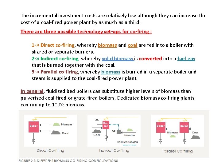
The incremental investment costs are relatively low although they can increase the cost of a coal-fired power plant by as much as a third. There are three possible technology set-ups for co-firing : 1 -» Direct co-firing, whereby biomass and coal are fed into a boiler with shared or separate burners. 2 -» Indirect co-firing, whereby solid biomass is converted into a fuel gas that is burned together with the coal. 3 -» Parallel co-firing, whereby biomass is burned in a separate boiler and steam is supplied to the coal-fired power plant. In general, fluidized boilers can substitute higher levels of biomass than pulverised coal-fired or grate-fired boilers. Dedicated biomass co-firing plants can run up to 100% biomass.
Biogas plant history , designs and energy calculations Part (3) Electricity production from biogas
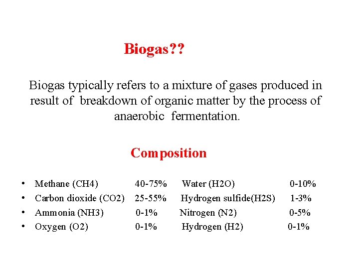
Biogas? ? Biogas typically refers to a mixture of gases produced in result of breakdown of organic matter by the process of anaerobic fermentation. Composition • • Methane (CH 4) 40 -75% Water (H 2 O) 0 -10% Carbon dioxide (CO 2) 25 -55% Hydrogen sulfide(H 2 S) 1 -3% Ammonia (NH 3) 0 -1% Nitrogen (N 2) 0 -5% Oxygen (O 2) 0 -1% Hydrogen (H 2) 0 -1%
Introduction
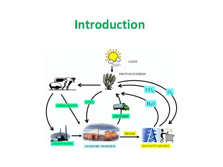
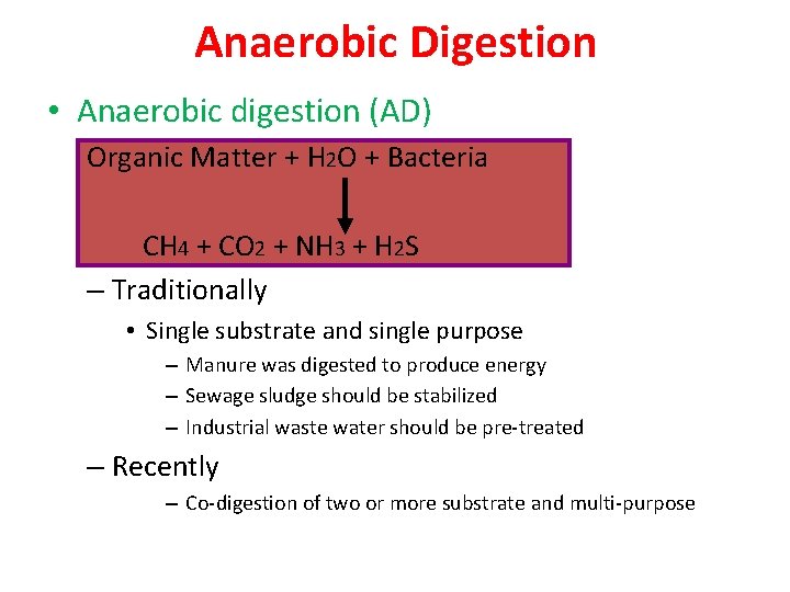
Anaerobic Digestion • Anaerobic digestion (AD) Organic Matter + H 2 O + Bacteria CH 4 + CO 2 + NH 3 + H 2 S – Traditionally • Single substrate and single purpose – Manure was digested to produce energy – Sewage sludge should be stabilized – Industrial waste water should be pre-treated – Recently – Co-digestion of two or more substrate and multi-purpose
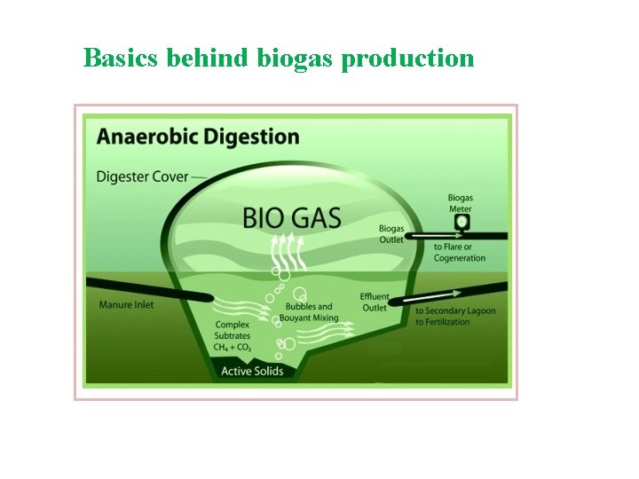
Introduction of biogas plant • Biogas plant is name often given to an anaerobic digester that treats farm or organic wastes. • The history of biogas plants goes back to ancient Persia and China. It was observed that rotting vegetables produce flammable gas.
Basics behind biogas production
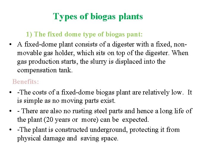
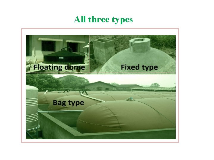
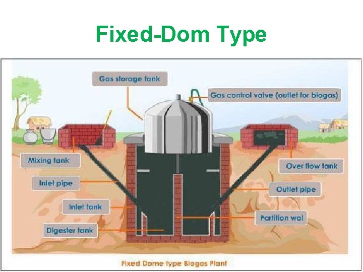
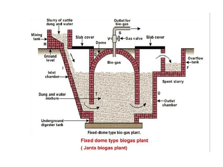
Types of biogas plants 1) The fixed dome type of biogas pant: • A fixed-dome plant consists of a digester with a fixed, nonmovable gas holder, which sits on top of the digester. When gas production starts, the slurry is displaced into the compensation tank. Benefits: • -The costs of a fixed-dome biogas plant are relatively low. It is simple as no moving parts exist. • - There also no rusting steel parts and hence a long life of the plant (20 years or more) can be expected. • -The plant is constructed underground, protecting it from physical damage and saving space.
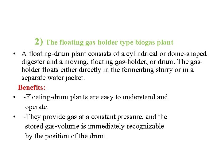
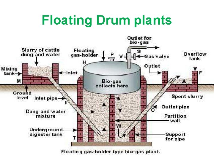
2) The floating gas holder type biogas plant • A floating-drum plant consists of a cylindrical or dome-shaped digester and a moving, floating gas-holder, or drum. The gasholder floats either directly in the fermenting slurry or in a separate water jacket. Benefits: • -Floating-drum plants are easy to understand operate. • -They provide gas at a constant pressure, and the stored gas-volume is immediately recognizable by the position of the drum.
3) Bag type biogas plant • The bag-type plant is manufactured high-strength PVCpolyester fabric and other compounds. Benefits • More efficiency • No gas leakage
All three types
Construction of biogas plant Part(4)
Construction of biogas plant Site selection for biogas plant: • -To make plant operation easier and to avoid wastage of raw feedstock -The plant must be as close as possible to the feedstock supply and water source. • -The edge of the foundation of the plant should be at least two meters away from any other structures to avoid risk of damage during construction.
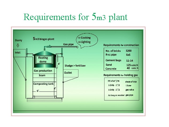
Carrying dung from shed to biogas plant: • On-farm biogas plants are feed with animal dung from adapted animal sheds, mixed with water and channel it into fermentation pits. These specified channels are so inclined that water mixed dung spontaneously flow toward the biogas plant therefore no extra labor is required to carry it. • If farmer is unable to afford the collection of dung by channels so it could be manual (carry & put) so no cost of construction for building these specific channels
Requirements for 5 m 3 plant
Fixed-Dom Type
Floating Drum plants
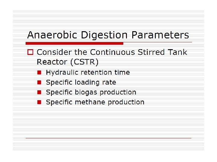
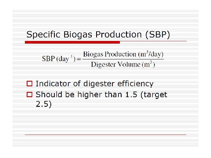
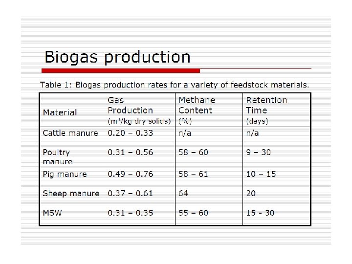
* The heat of combustion is called the upper calorific value, * example of the solid fuel is wood. The dry weight of wood contains about 50% carbon, 6. 3% hydrogen and 44. 2% oxygen. During the combustion of wood we obtain relatively small (0. 3 - 1%) amount of ash. Wood is classified as biomass. Anaerobic digester parameters Biogas production Digester heat balance
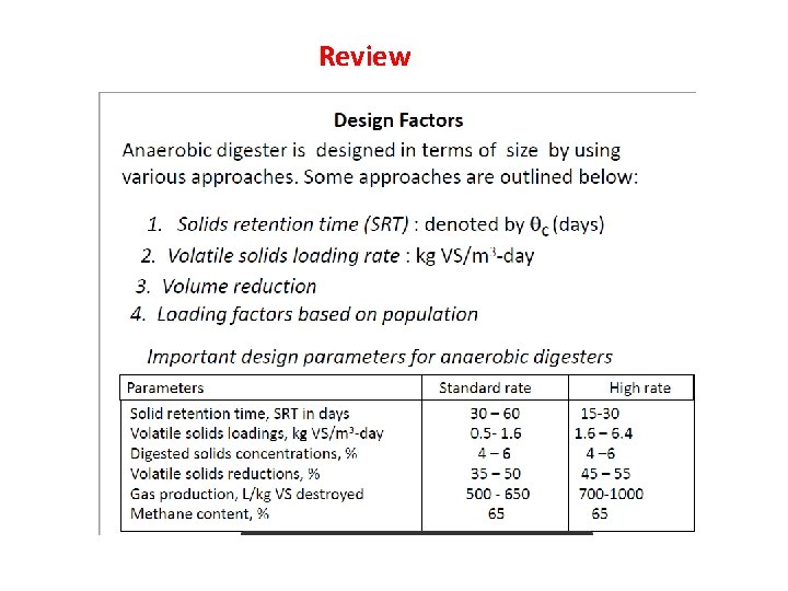
Review
ANAEROBIC SLUDGE DIGESTION PROCESS Part(5)
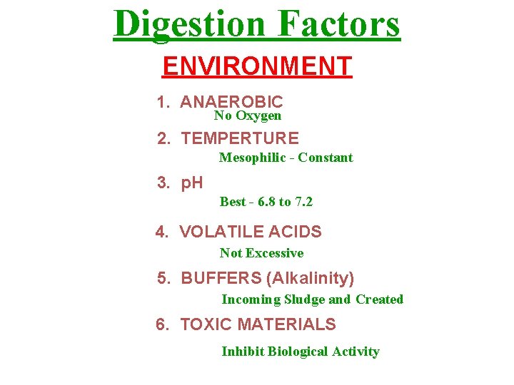
Digestion Factors ENVIRONMENT 1. ANAEROBIC No Oxygen 2. TEMPERTURE Mesophilic - Constant 3. p. H Best - 6. 8 to 7. 2 4. VOLATILE ACIDS Not Excessive 5. BUFFERS (Alkalinity) Incoming Sludge and Created 6. TOXIC MATERIALS Inhibit Biological Activity
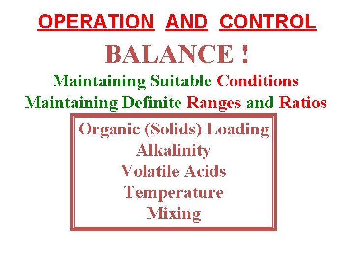
OPERATION AND CONTROL BALANCE ! Maintaining Suitable Conditions Maintaining Definite Ranges and Ratios Organic (Solids) Loading Alkalinity Volatile Acids Temperature Mixing
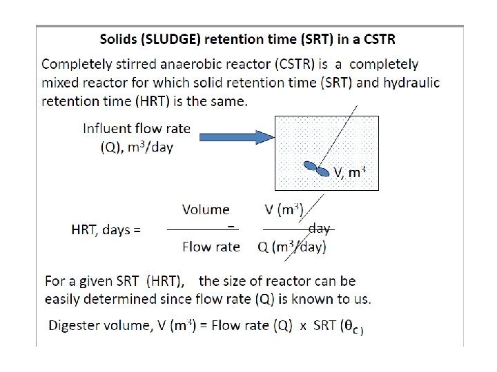
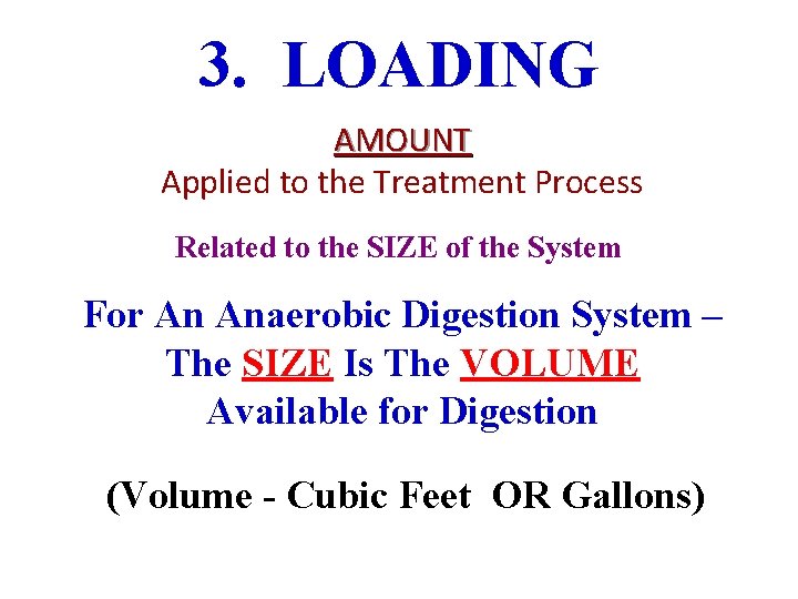
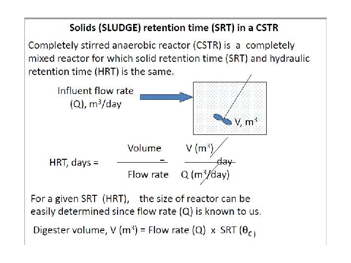
3. LOADING AMOUNT Applied to the Treatment Process Related to the SIZE of the System For An Anaerobic Digestion System – The SIZE Is The VOLUME Available for Digestion (Volume - Cubic Feet OR Gallons)
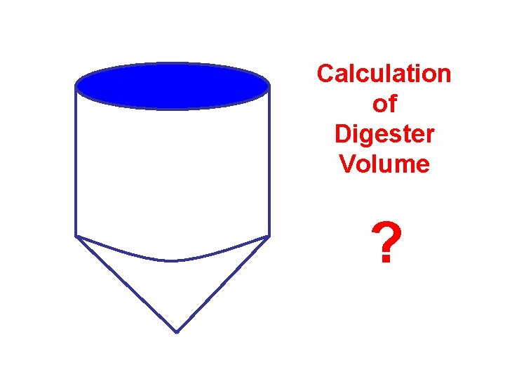
Calculation of Digester Volume ?
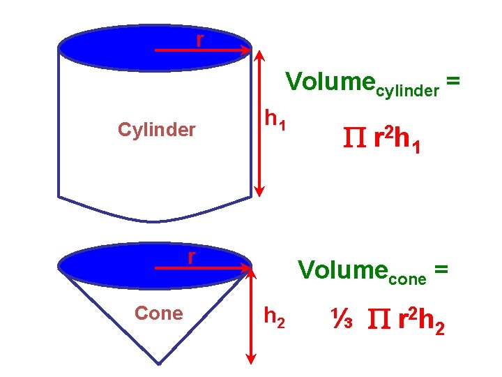
r Volumecylinder = Cylinder h 1 r Cone r 2 h 1 Volumecone = h 2 ⅓ r 2 h 2
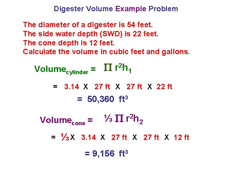
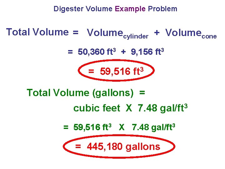
Digester Volume Example Problem The diameter of a digester is 54 feet. The side water depth (SWD) is 22 feet. The cone depth is 12 feet. Calculate the volume in cubic feet and gallons. Volumecylinder = r 2 h 1 = 3. 14 X 27 ft X 22 ft = 50, 360 ft 3 Volumecone = = ⅓X ⅓ r 2 h 2 3. 14 X 27 ft X 12 ft = 9, 156 ft 3
Digester Volume Example Problem Total Volume = Volumecylinder + Volumecone = 50, 360 ft 3 + 9, 156 ft 3 = 59, 516 ft 3 Total Volume (gallons) = cubic feet X 7. 48 gal/ft 3 = 59, 516 ft 3 X 7. 48 gal/ft 3 = 445, 180 gallons
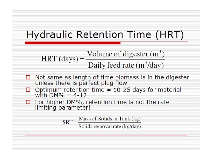
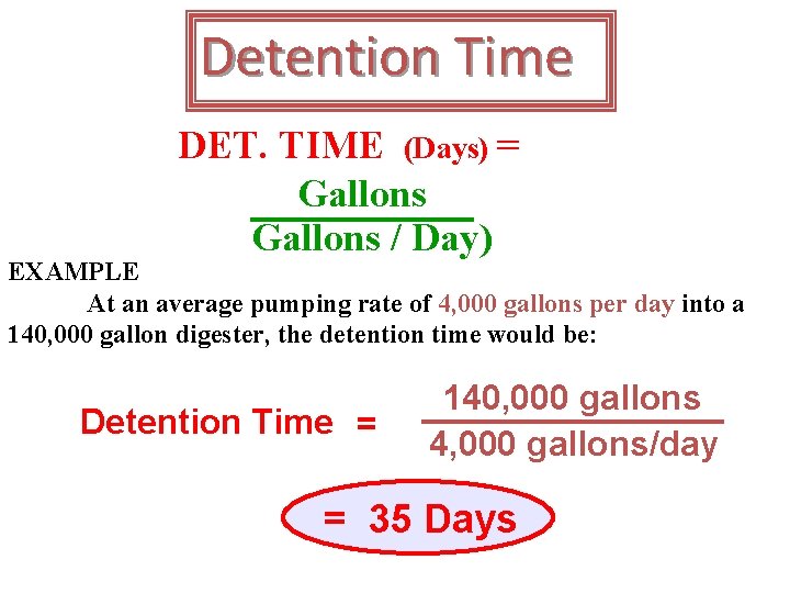
Detention Time DET. TIME (Days) = Gallons / Day) EXAMPLE At an average pumping rate of 4, 000 gallons per day into a 140, 000 gallon digester, the detention time would be: Detention Time = 140, 000 gallons 4, 000 gallons/day = 35 Days
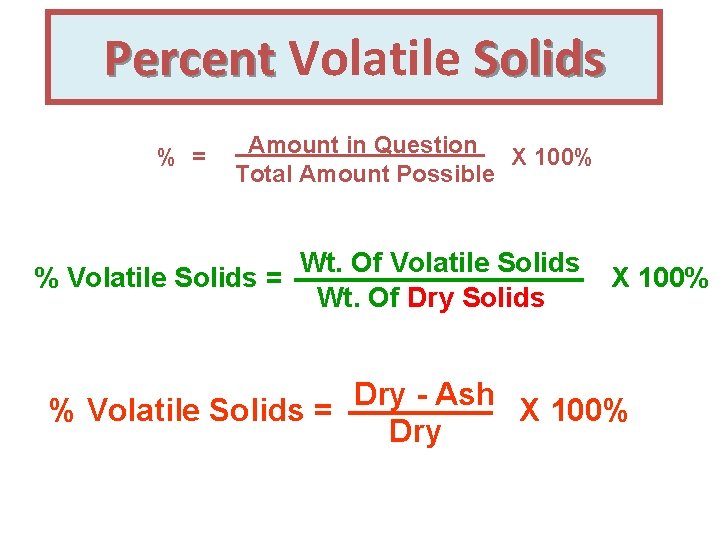
Percent Volatile Solids % = Amount in Question X 100% Total Amount Possible % Volatile Solids = Wt. Of Volatile Solids Wt. Of Dry Solids X 100% Dry Ash % Volatile Solids = X 100% Dry
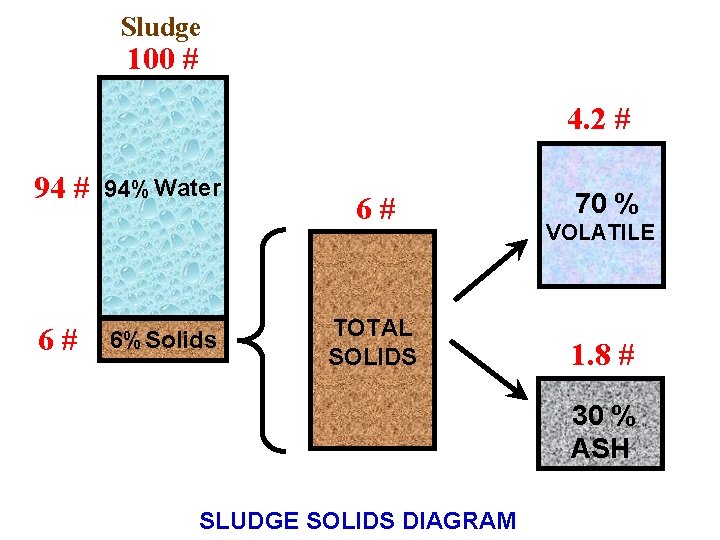
Sludge 100 # 4. 2 # 94 # 6# 94% Water 6% Solids 6# TOTAL SOLIDS 70 % VOLATILE 1. 8 # 30 % ASH SLUDGE SOLIDS DIAGRAM
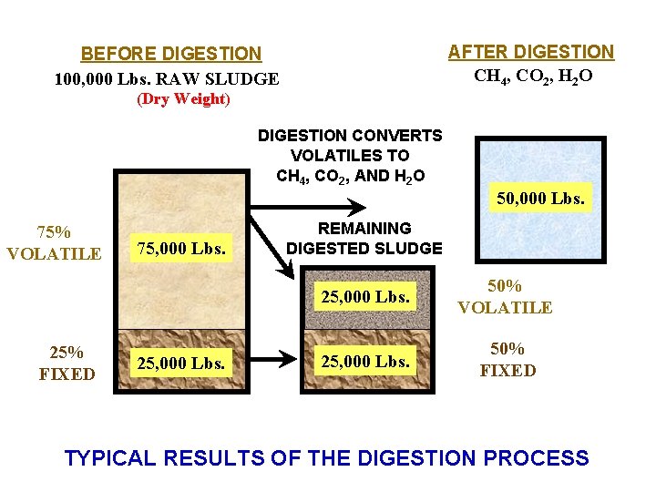
AFTER DIGESTION CH 4, CO 2, H 2 O BEFORE DIGESTION 100, 000 Lbs. RAW SLUDGE (Dry Weight) DIGESTION CONVERTS VOLATILES TO CH 4, CO 2, AND H 2 O 50, 000 Lbs. 75% VOLATILE 25% FIXED 75, 000 Lbs. 25, 000 Lbs. REMAINING DIGESTED SLUDGE 25, 000 Lbs. 50% VOLATILE 25, 000 Lbs. 50% FIXED TYPICAL RESULTS OF THE DIGESTION PROCESS
SLUDGE POUNDS CALCULATIONS
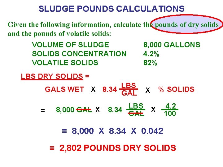
SLUDGE POUNDS CALCULATIONS Given the following information, calculate the pounds of dry solids and the pounds of volatile solids: VOLUME OF SLUDGE SOLIDS CONCENTRATION VOLATILE SOLIDS 8, 000 GALLONS 4. 2% 82% LBS DRY SOLIDS = GALS WET X 8. 34 LBS GAL = 8, 000 GAL X X % SOLIDS 8. 34 LBS GAL X 4. 2 100 = 8, 000 X 8. 34 X 0. 042 = 2, 802 POUNDS DRY SOLIDS
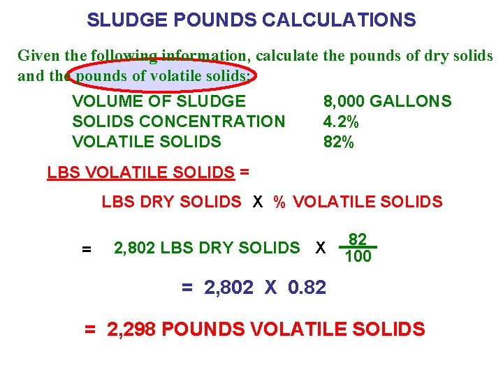
SLUDGE POUNDS CALCULATIONS Given the following information, calculate the pounds of dry solids and the pounds of volatile solids: VOLUME OF SLUDGE SOLIDS CONCENTRATION VOLATILE SOLIDS 8, 000 GALLONS 4. 2% 82% LBS VOLATILE SOLIDS = LBS DRY SOLIDS X % VOLATILE SOLIDS = 2, 802 LBS DRY SOLIDS X 82 100 = 2, 802 X 0. 82 = 2, 298 POUNDS VOLATILE SOLIDS
ORGANIC LOADING CALCULATIONS
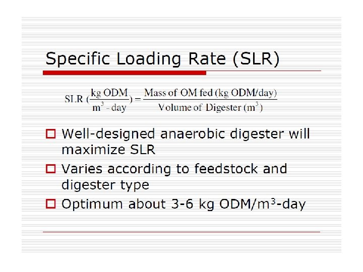
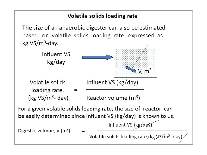
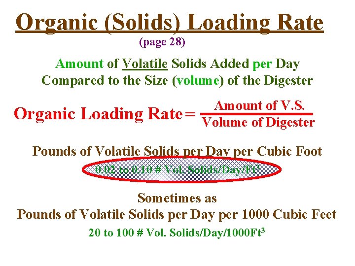
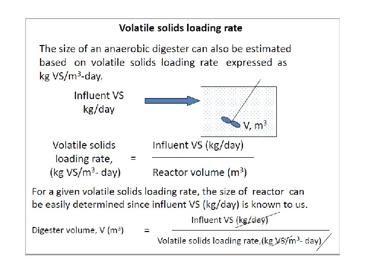
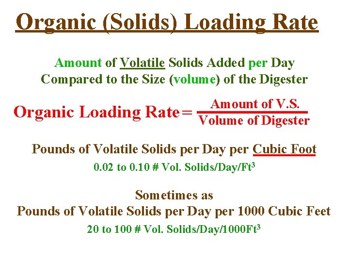
Organic (Solids) Loading Rate (page 28) Amount of Volatile Solids Added per Day Compared to the Size (volume) of the Digester Organic Loading Rate = Amount of V. S. Volume of Digester Pounds of Volatile Solids per Day per Cubic Foot 0. 02 to 0. 10 # Vol. Solids/Day/Ft 3 Sometimes as Pounds of Volatile Solids per Day per 1000 Cubic Feet 20 to 100 # Vol. Solids/Day/1000 Ft 3
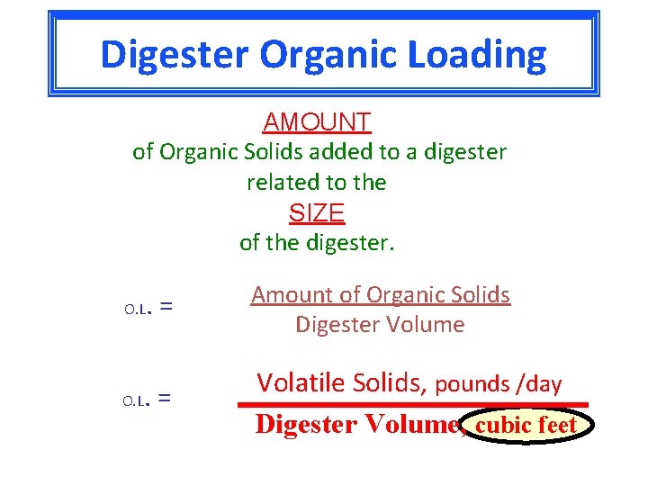
Digester Organic Loading AMOUNT of Organic Solids added to a digester related to the SIZE of the digester. . = Amount of Organic Solids Digester Volume . = Volatile Solids, pounds /day Digester Volume, cubic feet O. L
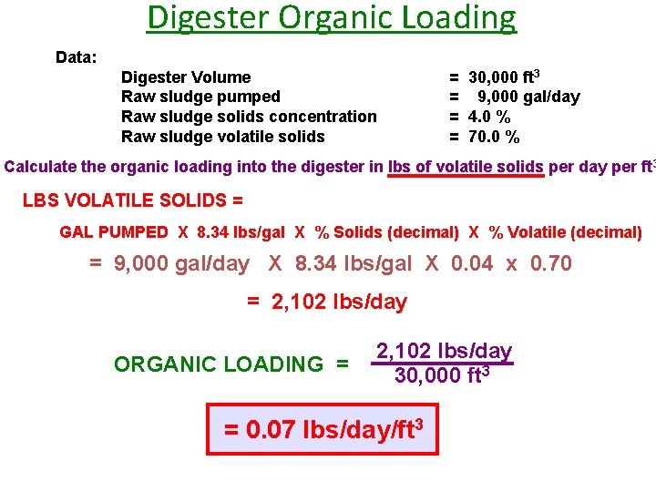
Digester Organic Loading Data: Digester Volume Raw sludge pumped Raw sludge solids concentration Raw sludge volatile solids = 30, 000 ft 3 = 9, 000 gal/day = 4. 0 % = 70. 0 % Calculate the organic loading into the digester in lbs of volatile solids per day per ft 3 LBS VOLATILE SOLIDS = GAL PUMPED X 8. 34 lbs/gal X % Solids (decimal) X % Volatile (decimal) = 9, 000 gal/day X 8. 34 lbs/gal X 0. 04 x 0. 70 = 2, 102 lbs/day ORGANIC LOADING = 2, 102 lbs/day 30, 000 ft 3 = 0. 07 lbs/day/ft 3
Digester Efficiency Reduction Of Volatile Solids
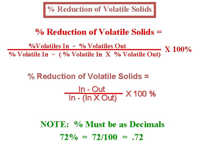
% Reduction of Volatile Solids = %Volatiles In - % Volatiles Out X 100% % Volatile In - ( % Volatile In X % Volatile Out) % Reduction of Volatile Solids = In - Out In - (In X Out) X 100 % NOTE: % Must be as Decimals 72% = 72/100 =. 72
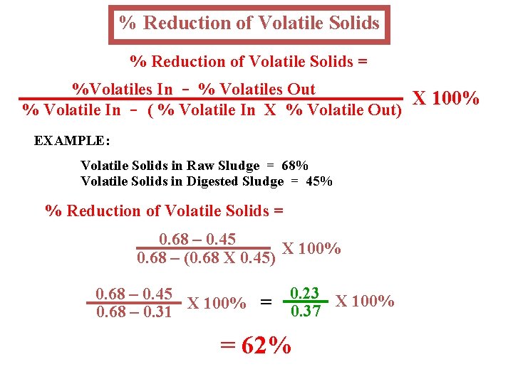
% Reduction of Volatile Solids = %Volatiles In - % Volatiles Out X 100% % Volatile In - ( % Volatile In X % Volatile Out) EXAMPLE: Volatile Solids in Raw Sludge = 68% Volatile Solids in Digested Sludge = 45% % Reduction of Volatile Solids = 0. 68 – 0. 45 X 100% 0. 68 – (0. 68 X 0. 45) 0. 68 – 0. 45 X 100% = 0. 68 – 0. 31 0. 23 X 100% 0. 37 = 62%
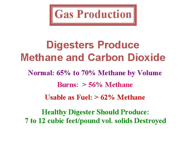
Gas Production Digesters Produce Methane and Carbon Dioxide Normal: 65% to 70% Methane by Volume Burns: > 56% Methane Usable as Fuel: > 62% Methane Healthy Digester Should Produce: 7 to 12 cubic feet/pound vol. solids Destroyed
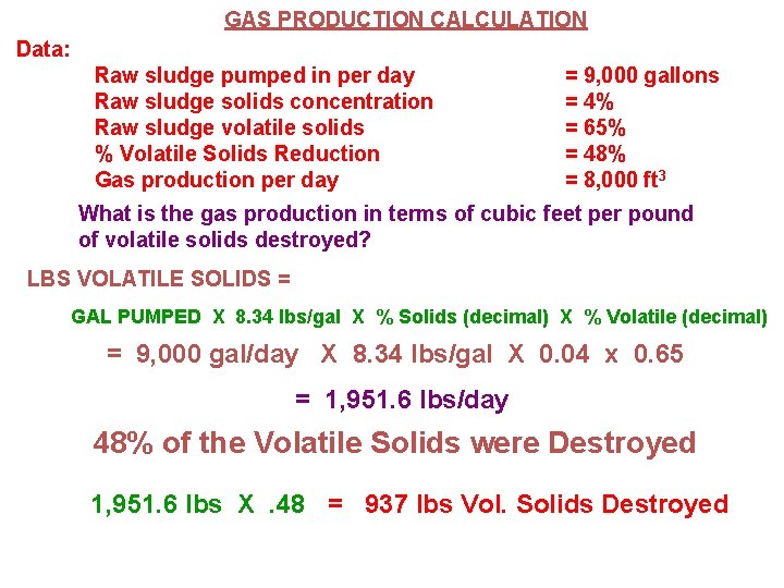
GAS PRODUCTION CALCULATION Data: Raw sludge pumped in per day Raw sludge solids concentration Raw sludge volatile solids % Volatile Solids Reduction Gas production per day = 9, 000 gallons = 4% = 65% = 48% = 8, 000 ft 3 What is the gas production in terms of cubic feet per pound of volatile solids destroyed? LBS VOLATILE SOLIDS = GAL PUMPED X 8. 34 lbs/gal X % Solids (decimal) X % Volatile (decimal) = 9, 000 gal/day X 8. 34 lbs/gal X 0. 04 x 0. 65 = 1, 951. 6 lbs/day 48% of the Volatile Solids were Destroyed 1, 951. 6 lbs X. 48 = 937 lbs Vol. Solids Destroyed
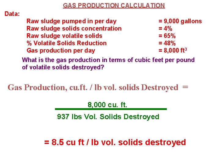
GAS PRODUCTION CALCULATION Data: Raw sludge pumped in per day Raw sludge solids concentration Raw sludge volatile solids % Volatile Solids Reduction Gas production per day = 9, 000 gallons = 4% = 65% = 48% = 8, 000 ft 3 What is the gas production in terms of cubic feet per pound of volatile solids destroyed? Gas Production, cu. ft. / lb vol. solids Destroyed = 8, 000 cu. ft. 937 lbs Vol. Solids Destroyed = 8. 5 cu ft / lb vol. solids destroyed
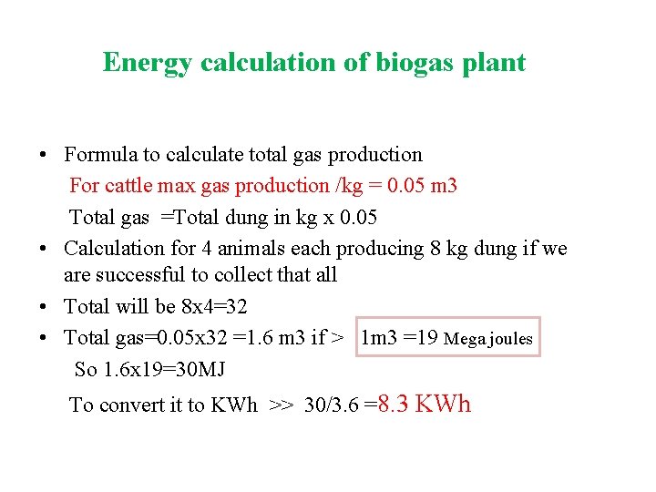
Energy calculation of biogas plant • Formula to calculate total gas production For cattle max gas production /kg = 0. 05 m 3 Total gas =Total dung in kg x 0. 05 • Calculation for 4 animals each producing 8 kg dung if we are successful to collect that all • Total will be 8 x 4=32 • Total gas=0. 05 x 32 =1. 6 m 3 if > 1 m 3 =19 Mega joules So 1. 6 x 19=30 MJ To convert it to KWh >> 30/3. 6 =8. 3 KWh
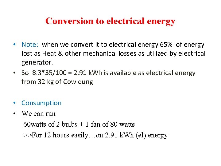
Conversion to electrical energy • Note: when we convert it to electrical energy 65% of energy lost as Heat & other mechanical losses as utilized by electrical generator. • So 8. 3*35/100 = 2. 91 k. Wh is available as electrical energy from 32 kg of Cow dung • Consumption • We can run 60 watts of 2 bulbs + 1 fan of 80 watts >>For 12 hours easily…on 2. 91 k. Wh (el) energy
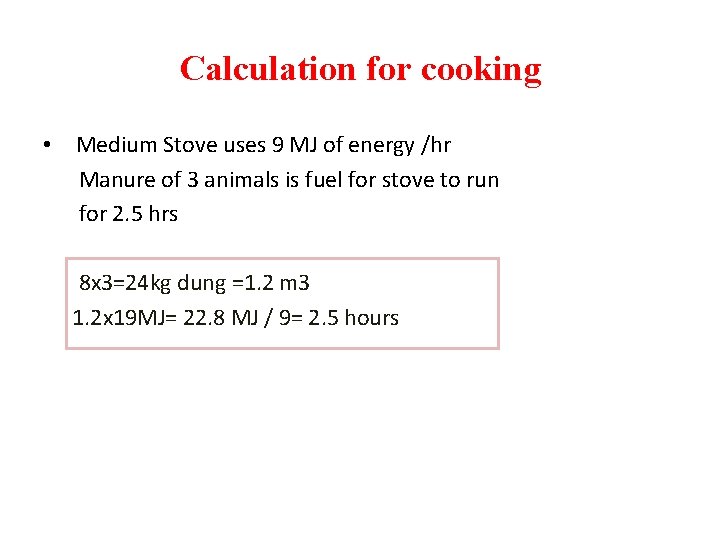
Calculation for cooking • Medium Stove uses 9 MJ of energy /hr Manure of 3 animals is fuel for stove to run for 2. 5 hrs 8 x 3=24 kg dung =1. 2 m 3 1. 2 x 19 MJ= 22. 8 MJ / 9= 2. 5 hours
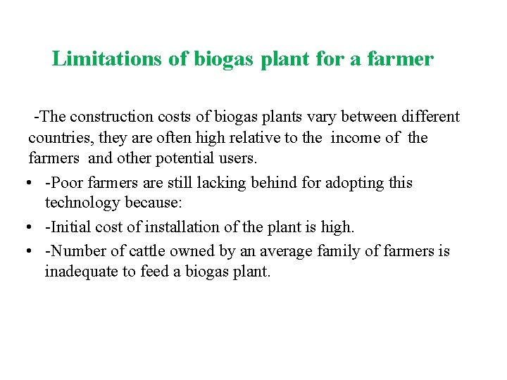
Limitations of biogas plant for a farmer -The construction costs of biogas plants vary between different countries, they are often high relative to the income of the farmers and other potential users. • -Poor farmers are still lacking behind for adopting this technology because: • -Initial cost of installation of the plant is high. • -Number of cattle owned by an average family of farmers is inadequate to feed a biogas plant.
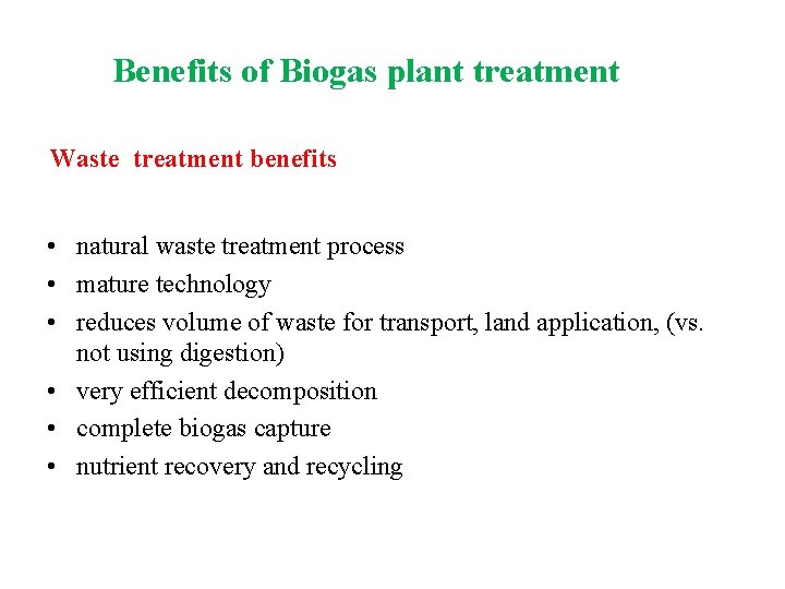
Benefits of Biogas plant treatment Waste treatment benefits • natural waste treatment process • mature technology • reduces volume of waste for transport, land application, (vs. not using digestion) • very efficient decomposition • complete biogas capture • nutrient recovery and recycling
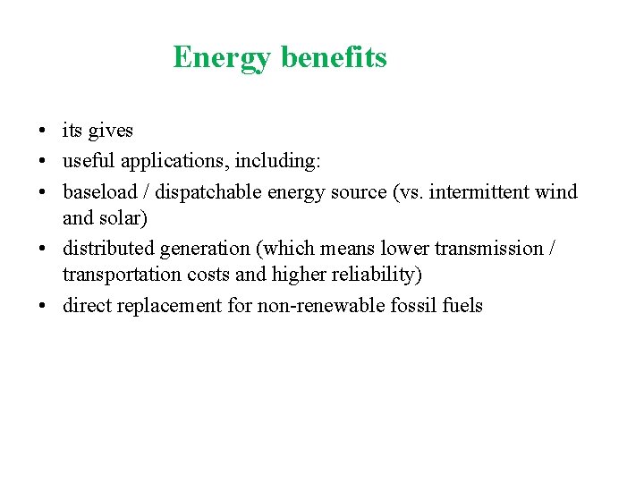
Energy benefits • its gives • useful applications, including: • baseload / dispatchable energy source (vs. intermittent wind and solar) • distributed generation (which means lower transmission / transportation costs and higher reliability) • direct replacement for non-renewable fossil fuels
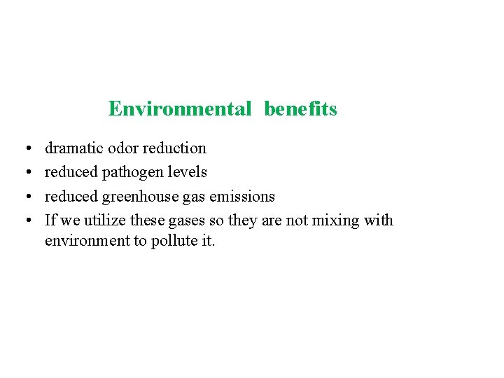
Environmental benefits • • dramatic odor reduction reduced pathogen levels reduced greenhouse gas emissions If we utilize these gases so they are not mixing with environment to pollute it.
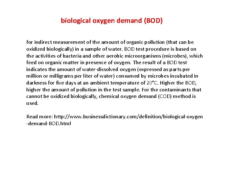
biological oxygen demand (BOD) for indirect measurement of the amount of organic pollution (that can be oxidized biologically) in a sample of water. BOD test procedure is based on the activities of bacteria and other aerobic microorganisms (microbes), which feed on organic matter in presence of oxygen. The result of a BOD test indicates the amount of water-dissolved oxygen (expressed as parts per million or milligrams per liter of water) consumed by microbes incubated in darkness for five days at an ambient temperature of 20°C. Higher the BOD, higher the amount of pollution in the test sample. For the contaminants that cannot be oxidized biologically, chemical oxygen demand (COD) method is used. Read more: http: //www. businessdictionary. com/definition/biological-oxygen -demand-BOD. html
Organic (Solids) Loading Rate Amount of Volatile Solids Added per Day Compared to the Size (volume) of the Digester Organic Loading Rate = Amount of V. S. Volume of Digester Pounds of Volatile Solids per Day per Cubic Foot 0. 02 to 0. 10 # Vol. Solids/Day/Ft 3 Sometimes as Pounds of Volatile Solids per Day per 1000 Cubic Feet 20 to 100 # Vol. Solids/Day/1000 Ft 3