Drawing Plane Graphs Takao Nishizeki Tohoku University US


 time algorithm Convex drawing Tutte 1963")


")


![Outline G linear time [RNN 98 a] Rectangular drawing](https://slidetodoc.com/presentation_image_h/885b3388e897752ea04192ca463863db/image-94.jpg "Outline G linear time [RNN 98 a] Rectangular drawing")
![Outline G Box-rectangular drawing linear time [RNN 98 a]](https://slidetodoc.com/presentation_image_h/885b3388e897752ea04192ca463863db/image-95.jpg "Outline G Box-rectangular drawing linear time [RNN 98 a]")
![Outline Time complexity O(n) G Box-rectangular drawing linear time [RNN 98 a]](https://slidetodoc.com/presentation_image_h/885b3388e897752ea04192ca463863db/image-96.jpg "Outline Time complexity O(n) G Box-rectangular drawing linear time [RNN 98 a]")


![Outline of the algorithm of [RNN 99] b b c a a d d](https://slidetodoc.com/presentation_image_h/885b3388e897752ea04192ca463863db/image-105.jpg "Outline of the algorithm of [RNN 99] b b c a a d d")


 x x z G(C) y y z orthogonal")


![4 -canonical decomposition[NRN 97] (a generalization of st-numbering) Gk -1 U 12 Uk (a)](https://slidetodoc.com/presentation_image_h/885b3388e897752ea04192ca463863db/image-117.jpg "4 -canonical decomposition[NRN 97] (a generalization of st-numbering) Gk -1 U 12 Uk (a)")
![4 -canonical decomposition[NRN 97] (a generalization of st-numbering) Gk -1 (a) Gk Gk -1](https://slidetodoc.com/presentation_image_h/885b3388e897752ea04192ca463863db/image-118.jpg "4 -canonical decomposition[NRN 97] (a generalization of st-numbering) Gk -1 (a) Gk Gk -1")
![4 -canonical decomposition[NRN 97] (a generalization of st-numbering) Gk -1 U 12 (a) U](https://slidetodoc.com/presentation_image_h/885b3388e897752ea04192ca463863db/image-119.jpg "4 -canonical decomposition[NRN 97] (a generalization of st-numbering) Gk -1 U 12 (a) U")
![4 -canonical decomposition[NRN 97] (a generalization of st-numbering) Gk -1 (a) Gk face U](https://slidetodoc.com/presentation_image_h/885b3388e897752ea04192ca463863db/image-120.jpg "4 -canonical decomposition[NRN 97] (a generalization of st-numbering) Gk -1 (a) Gk face U")
![4 -canonical decomposition[NRN 97] (a generalization of st-numbering) Gk -1 U 12 (a) U](https://slidetodoc.com/presentation_image_h/885b3388e897752ea04192ca463863db/image-121.jpg "4 -canonical decomposition[NRN 97] (a generalization of st-numbering) Gk -1 U 12 (a) U")
![4 -canonical decomposition[NRN 97] (a generalization of st-numbering) Gk -1 (a) Gk face U](https://slidetodoc.com/presentation_image_h/885b3388e897752ea04192ca463863db/image-122.jpg "4 -canonical decomposition[NRN 97] (a generalization of st-numbering) Gk -1 (a) Gk face U")
![4 -canonical decomposition[NRN 97] O(n) (a generalization of st-numbering) U 12 20 19 18](https://slidetodoc.com/presentation_image_h/885b3388e897752ea04192ca463863db/image-123.jpg "4 -canonical decomposition[NRN 97] O(n) (a generalization of st-numbering) U 12 20 19 18")

![Known Result Garg and Tamassia [GT 96] time algorithm for finding an orthogonal drawing](https://slidetodoc.com/presentation_image_h/885b3388e897752ea04192ca463863db/image-125.jpg "Known Result Garg and Tamassia [GT 96] time algorithm for finding an orthogonal drawing")
![Outline of the algorithm of [RNN 99] b c d d b a d](https://slidetodoc.com/presentation_image_h/885b3388e897752ea04192ca463863db/image-126.jpg "Outline of the algorithm of [RNN 99] b c d d b a d")

![Rectangular Drawing Algorithm of [RNN 98] Input Partition-pair Splitting](https://slidetodoc.com/presentation_image_h/885b3388e897752ea04192ca463863db/image-128.jpg "Rectangular Drawing Algorithm of [RNN 98] Input Partition-pair Splitting")


 (1) (1, n) is an edge of G (2) Each](https://slidetodoc.com/presentation_image_h/885b3388e897752ea04192ca463863db/image-136.jpg "st-numbering[E 79](2 -connected graph) (1) (1, n) is an edge of G (2) Each")
![Step 1: 4 -canonical ordering [KH 97] (4 -connected graph) (a generalization of st-numbering)](https://slidetodoc.com/presentation_image_h/885b3388e897752ea04192ca463863db/image-137.jpg "Step 1: 4 -canonical ordering [KH 97] (4 -connected graph) (a generalization of st-numbering)")


 = W’ = < n/2 -1")


- Slides: 165
Drawing Plane Graphs Takao Nishizeki Tohoku University
US President California Governor
US President California Governor What is the common feature?
Graphs and Graph Drawings STATION ATM-RT ATM-SW TPDDI ATM-RT STATION ATM-HUB STATION ATM-SW STATION ATM-HUB TPDDI ATM-SW ATM-RT ATM-HUB ATM-RT STATION ATM-HUB ATM-SW TPDDI STATION ATM-HUB STATION STATION A diagram of a computer network
Objectives of Graph Drawings Symmetric Eades, Hong Nice drawing structure of the graph is difficult to understand structure of the graph is easy to understand To obtain a nice representation of a graph so that the structure of the graph is easily understandable.
Objectives of Graph Drawings Nice drawing Modern beauty Ancient beauty
Objectives of Graph Drawings Diagram of an electronic circuit 5 7 8 Wire crossings 7 5 4 8 1 2 3 not suitable for single layered PCB 6 1 2 4 3 suitable for single layered PCB The drawing should satisfy some criterion arising from the application point of view.
Drawings of Plane Graphs Straight line drawing Convex drawing
Drawings of Plane Graphs Rectangular drawing Box-rectangular drawing Orthogonal drawing
Book Planar Graph Drawing by Takao Nishizeki Md. Saidur Rahman http: //www. nishizeki. ecei. tohoku. ac. jp/nszk/saidur/gdbook. html
Straight Line Drawing Plane graph
Straight Line Drawing Straight line drawing Plane graph
Straight Line Drawing Straight line drawing Plane graph Each vertex is drawn as a point.
Straight Line Drawing Straight line drawing Plane graph Each vertex is drawn as a point. Each edge is drawn as a single straight line segment.
Every plane graph has a straight line drawing. Straight Line Drawing Wagner ’ 36 Fary ’ 48 Polynomial-time algorithm Straight line drawing Plane graph Each vertex is drawn as a point. Each edge is drawn as a single straight line segment.
Straight Line Drawing W H Straight line drawing Plane graph W H
Straight Line Grid Drawing Straight line grid drawing. Plane graph In a straight line grid drawing each vertex is drawn on a grid point.
Wagner ’ 36 Fary ’ 48 Grid-size is not polynomial of the number of vertices n Straight line grid drawing. Plane graph
Straight Line Grid Drawing Straight line grid drawing. Plane graph de Fraysseix et al. ’ 90
Chrobak and Payne ’ 95 Linear algorithm Straight line grid drawing. Plane graph de Fraysseix et al. ’ 90
Schnyder ’ 90 H n-2 W Upper bound
What is the minimum size of a grid required for a straight line drawing?
Lower Bound
A restricted class of plane graphs may have more compact grid drawing. Triangulated plane graph 3 -connected graph
4 -connected ? not 4 -connected disconnected
How much area is required for 4 -connected plane graphs?
Straight line grid drawing Miura et al. ’ 01 Input: 4 -connected plane graph G Output: a straight line grid drawing Grid Size : Area: H= < n/2 W= < n/2
Miura et al. ’ 01 Schnyder ’ 90 4 -connected plane graph G n-2 H< = n/2 n-2 . 2 Area=n. Area <= 1/4 W= < n/2 2 Area<n = /4
The algorithm of Miura et al. is best possible
Triangulate all inner faces Step 1: find a 4 -canonical ordering n=18 n-1=17 16 15 8 7 3 1 12 14 10 8 5 6 11 13 n/2=9 5 6 7 4 2 G Step 3 and 4 : Draw G’ and G” in isosceles right-angled 1 triangles n=18 16 15 13 9 11 G” n-1=17 Step 2: Divide G into two halves G’ and G” 12 14 10 Main idea 3 G’ 4 2 G” W/2 |slope|>11 G Step 5: Combine the drawings of G’ and G” n/2 W/2 |slope|<1 = G’ W =< n/2 -1
Draw a graph G on the plane “nicely” Straight line drawing A convex drawing is a straight line drawing where each face is drawn as a convex polygon. Convex drawing
Convex Drawing Convex drawing Tutte 1963 Every 3 -connected planar graph has a convex drawing. A necessary and sufficient condition for a plane graph to have a convex drawing. Thomassen ’ 80
Convex Drawing Chiba et al. ’ 84 O(n) time algorithm Convex drawing Tutte 1963 Every 3 -connected planar graph has a convex drawing A necessary and sufficient condition for a plane graph to have a convex drawing. Thomassen ’ 80
Convex Grid Drawing Chrobak and Kant ’ 97 Input: 3 -connected graph Output: convex grid drawing n-2 Grid Size Area
Convex Grid Drawing Miura et al. 2000 Input : 4 -connected plane graph Output: Convex grid drawing Grid Size Half-perimeter Area H W
Miura et al. Chrobak and Kant ’ 97 3 -connected graph 2000 4 -connected graph n-2 H n-2 Area <= 1/4 W Area
The algorithm of Miura et al. is best possible H W
Main idea 20 21 19 18 15 13 10 16 9 6 18 14 8 6 5 1: 4 -canonical decomposition O(n)[NRN 97] 21 20 13 1 6 3 17 11 12 10 7 8 4 14 8 7 4 1 5 2 2: Find paths 3: Decide x-coordinates 19 9 16 11 9 10 3 2 15 12 13 1 16 17 15 12 11 4 18 19 17 7 3 21 20 14 4: Decide y-coordinates 5 2 Time complexity: O(n)
VLSI Floorplanning B A F E G C D Interconnection graph
VLSI Floorplanning B A F E G E C F G C D D Interconnection graph VLSI floorplan
VLSI Floorplanning B A F E G E C F G C D D Interconnection graph VLSI floorplan
VLSI Floorplanning B A F E G E C F G C D D Interconnection graph VLSI floorplan
VLSI Floorplanning B A F E E C G F G C D D Interconnection graph B A F E G C D Dual-like graph VLSI floorplan
VLSI Floorplanning B A F E E C G F G C D D Interconnection graph B A G B A F E VLSI floorplan C D Dual-like graph G C D Add four corners
VLSI Floorplanning B A F E E C G F G C D Rectangular drawing D Interconnection graph B A G B A F E VLSI floorplan C D Dual-like graph G C D Add four corners
Rectangular Drawings Plane graph G of Input
Rectangular Drawings Plane graph G of Input corner Rectangular drawing of G Output
Rectangular Drawings Plane graph G of corner Rectangular drawing of G Input Each vertex is drawn as a point. Output
Rectangular Drawings Plane graph G of corner Rectangular drawing of G Output Input Each vertex is drawn as a point. Each edge is drawn as a horizontal or a vertical line segment.
Rectangular Drawings Plane graph G of corner Rectangular drawing of G Output Input Each vertex is drawn as a point. Each edge is drawn as a horizontal or a vertical line segment. Each face is drawn as a rectangle.
Not every plane graph has a rectangular drawing.
Thomassen ’ 84, Necessary and sufficient condition Rahman, Nakano and Nishizeki ’ 98 Linear-time algorithms Rahman, Nakano and Nishizeki ’ 02 Linear algorithm for the case where corners are not designated in advance
A Necessary and Sufficient Condition by Thomassen ’ 84 plane graph G four vertices of degree 2 are designated as corners G has a rectangular drawing if and only if every 2 -legged cycle in G contains at least two designated vertices; and every 3 -legged cycle in G contains at least one designated vertex. 2 -legged cycles 3 -legged cycles
A Necessary and Sufficient Condition by Thomassen ’ 84 plane graph G four vertices of degree 2 are designated as corners G has a rectangular drawing if and only if every 2 -legged cycle in G contains at least two designated vertices; and every 3 -legged cycle in G contains at least one designated vertex. 2 -legged cycles
A Necessary and Sufficient Condition by Thomassen ’ 84 plane graph G four vertices of degree 2 are designated as corners G has a rectangular drawing if and only if every 2 -legged cycle in G contains at least two designated vertices; and every 3 -legged cycle in G contains at least one designated vertex. 2 -legged cycles 3 -legged cycles
A Necessary and Sufficient Condition by Thomassen ’ 84 plane graph G four vertices of degree 2 are designated as corners G has a rectangular drawing if and only if every 2 -legged cycle in G contains at least two designated vertices; and every 3 -legged cycle in G contains at least one designated vertex. Bad cycles 2 -legged cycles 3 -legged cycles
Outline of the Algorithm of Rahman et al.
Outline of the Algorithm of Rahman et al.
Outline of the Algorithm of Rahman et al.
Outline of the Algorithm of Rahman et al.
Outline of the Algorithm of Rahman et al.
Outline of the Algorithm of Rahman et al.
Bad cycle
Bad cycle
Partition-pair
Partition-pair Splitting
Partition-pair
Partition-pair
Partition-pair Rectangular drawing
Time complexity Partition-pair Rectangular drawing O(n)
Miura, Haga, N. ’ 03, Working paper Rectangular drawing of plane graph G with Δ ≤ 4 perfect matching in Gd
G
G Gd
G Gd perfect matching
G
VLSI Floorplanning B A F E G E C D F G C Rectangular drawing D Interconnection graph VLSI floorplan
VLSI Floorplanning B A F E G E C F G D C Rectangular drawing D Interconnection graph VLSI floorplan Unwanted adjacency Not desirable for MCM floorplanning and for some architectural floorplanning.
B A A F E G B F C D Interconnection graph E G C D MCM Floorplanning Sherwani Architectural Floorplanning Munemoto, Katoh, Imamura
B A A F E G B F C D Interconnection graph E G C D MCM Floorplanning Architectural Floorplanning
B A A F E B F C G E G C D D Interconnection graph A E G B F C D Dual-like graph MCM Floorplanning Architectural Floorplanning
B A A F E B F C G E G C D D Interconnection graph A E G B F C D Dual-like graph MCM Floorplanning Architectural Floorplanning
B A A F E B F E G C D D Interconnection graph A E G MCM Floorplanning Architectural Floorplanning B A F C D Dual-like graph E G D B F C
Box-Rectangular drawing B A A F E B F E G C dead space D D Interconnection graph A E G MCM Floorplanning Architectural Floorplanning B A F C D Dual-like graph E G D B F C
Box-Rectangular Drawing a b c d Plane multigraph G Input
Box-Rectangular Drawing a b c d Plane multigraph G Input a b d c Box-rectangular drawing Output
Box-Rectangular Drawing a b c d Plane multigraph G Input a b d c Box-rectangular drawing • Each vertex is drawn as a rectangle. Output
Box-Rectangular Drawing a b c d Plane multigraph G Input a b d c Box-rectangular drawing Output • Each vertex is drawn as a rectangle. • Each edge is drawn as a horizontal or a vertical line segment.
Box-Rectangular Drawing a b c d Plane multigraph G Input a b d c Box-rectangular drawing Output • Each vertex is drawn as a rectangle. • Each edge is drawn as a horizontal or a vertical line segment. • Each face is drawn as a rectangle.
Rahman et al. 2000 A necessary and sufficient condition for a plane multigraph to have a box-rectangular drawing. A linear-time algorithm. , where m is the number of edges in G. a b d c H W
Algorithm of Rahman et al. Main Idea: Reduction to a rectangular drawing problem
Outline G
Replace each vertex of degree four or more by a cycle Outline G
Outline G linear time [RNN 98 a] Rectangular drawing
Outline G Box-rectangular drawing linear time [RNN 98 a]
Outline Time complexity O(n) G Box-rectangular drawing linear time [RNN 98 a]
Orthogonal Drawings f g e h d i c a b plane graph G Input
Orthogonal Drawings f g i h e g h d i f e c a b plane graph G Input d c b a Output
Orthogonal Drawings f g i h e g h d i f e c a b plane graph G Input bends d c b a Output Each edge is drawn as an alternating sequence of horizontal and vertical line segments.
Orthogonal Drawings f g i h e g h d i f e c a b plane graph G Input bend d c b a Output Each edge is drawn as an alternating sequence of horizontal and vertical line segments. Each vertex is drawn as a point.
Applications Entity-relationship diagrams Flow diagrams
Applications Circuit schematics Minimization of bends reduces the number of “vias” or “throughholes, ” and hence reduces VLSI fabrication costs.
Objective f g i h e g h 9 bend d i f e c a b d c b a plane graph G g To minimize the number of bends in an orthogonal drawing. f 4 bends h i e d a b c minimum number of bends.
Bend-Minimum Orthogonal Drawing Garg and Tamassia ’ 96 time for plane graph of Δ ≤ 4 Idea reduction to a minimum cost flow problem Rahman, Nakano and Nishizeki ’ 99 Linear for 3 -connected cubic plane graph Idea reduction to a rectangular drawing problem. Rahman and Nishizeki ’ 02 Linear for plane graph of Δ≤ 3
Outline of the algorithm of [RNN 99] b b c a a d d a c b b a d d c orthogonal drawing of G c rectangular drawing of orthogonal drawings
Open Problems and Future Research Direction More area-efficient straight-line or convex drawing algorithms. for every planar graph? Linear algorithm for rectangular drawings of plane graphs of Δ ≤ 4. Linear algorithm for bend-minimal orthogonal drawings of plane graphs of Δ ≤ 4. Drawing of plane graphs with constraints like Prescribed face areas Practical Prescribed length of some edges Applications Prescribed positions of some vertices
Book Planar Graph Drawing by Takao Nishizeki Md. Saidur Rahman http: //www. nishizeki. ecei. tohoku. ac. jp/nszk/saidur/gdbook. html
Book Planar Graph Drawing by Takao Nishizeki Md. Saidur Rahman http: //www. nishizeki. ecei. tohoku. ac. jp/nszk/saidur/gdbook. html
ISAAC in Sendai, Tohoku Probably 2007
Kyoto Sendai Tokyo
Properties of a drawing of G(C) x x z G(C) y y z orthogonal drawing of G(C) minimum number of bends the six open halflines are free
Main idea 20 21 19 18 14 15 13 16 9 6 10 12 11 8 7 3 4 1 17 5 2 4 -canonical decomposition
Main idea 20 21 19 18 16 9 6 10 4 18 12 11 15 13 5 1 1 2 4 -canonical decomposition 19 16 8 7 3 21 20 14 15 13 17 9 17 11 12 14 10 7 8 6 3 4 5 2 Add a group of vertices one by one.
Main idea 20 21 19 18 16 9 6 10 4 18 12 11 15 13 5 1 1 2 4 -canonical decomposition 19 16 8 7 3 21 20 14 15 13 17 9 17 11 12 14 10 7 8 6 3 4 5 2 Add a group of vertices one by one.
Main idea 20 21 19 18 15 13 10 16 9 6 18 14 8 6 5 1: 4 -canonical decomposition O(n)[NRN 97] 21 20 13 1 6 3 17 11 12 10 7 8 4 14 8 7 4 1 5 2 2: Find paths 3: Decide x-coordinates 19 9 16 11 9 10 3 2 15 12 13 1 16 17 15 12 11 4 18 19 17 7 3 21 20 14 4: Decide y-coordinates 5 2 Time complexity: O(n)
4 -canonical decomposition[NRN 97] (a generalization of st-numbering) Gk -1 U 12 Uk (a) U 11 U 9 U 7 U 3 Gk U 8 U 10 U 5 U 6 U 4 Gk -1 Uk (b) U 2 face Gk U 1 Gk -1 G (c) Uk face Gk
4 -canonical decomposition[NRN 97] (a generalization of st-numbering) Gk -1 (a) Gk Gk -1 U 3 Gk (b) face Gk Gk -1 (c) face Gk
4 -canonical decomposition[NRN 97] (a generalization of st-numbering) Gk -1 U 12 (a) U 11 U 9 U 7 U 3 Gk U 8 U 10 U 5 U 6 U 4 Gk -1 (b) U 2 face Gk Gk -1 U 1 (c) face Gk
4 -canonical decomposition[NRN 97] (a generalization of st-numbering) Gk -1 (a) Gk face U 9 Gk -1 (b) face Gk Gk Gk -1 (c) face Gk
4 -canonical decomposition[NRN 97] (a generalization of st-numbering) Gk -1 U 12 (a) U 11 U 9 U 7 U 3 Gk U 8 U 10 U 5 U 6 U 4 Gk -1 (b) U 2 face Gk Gk -1 U 1 (c) face Gk
4 -canonical decomposition[NRN 97] (a generalization of st-numbering) Gk -1 (a) Gk face U 5 Gk -1 (b) face Gk Gk Gk -1 (c) face Gk
4 -canonical decomposition[NRN 97] O(n) (a generalization of st-numbering) U 12 20 19 18 15 13 U 7 U 3 U 11 U 9 16 U 5 10 7 3 U 2 4 Uk (a) 17 U 10 9 6 Gk -1 n = 21 Gk U 8 12 14 U 6 11 8 Gk -1 Uk U 4 (b) 5 face Gk 1 U 1 2 Gk -1 G (c) Uk face Gk
Orthogonal Drawings g h f i e h g 9 bends d i f e c d b a a plane graph G Input Output Each edge is drawn as an alternating sequence of horizontal and vertical line segments. Each vertex is drawn as a point. Applications Circuit schematics, Data-flow diagrams, Entityrelationship diagrams [T 87, BK 97]. Objective To minimize the number of bends in an orthogonal drawing. g c b f h i e d a c 4 bends an orthogonal drawing with the minimum number of bends. b
Known Result Garg and Tamassia [GT 96] time algorithm for finding an orthogonal drawing of a plane graph of Δ ≤ 4 with the minimum number of bends. Idea reduction to a minimum cost flow problem Rahman, Nakano and Nishizeki [RNN 99] A linear time algorithm to find an orthogonal drawing of a 3 -connected cubic plane graph with the minimum number of bends. Idea reduction to a rectangular drawing problem. Rahman and Nishizeki [RN 02] A linear time algorithm to find an orthogonal drawing of a plane graph of Δ≤ 3 with the minimum number of bends. Idea reduction to a no-bend drawing problem.
Outline of the algorithm of [RNN 99] b c d d b a d d c a a a b c orthogonal drawing of G Properties of a drawing of G(C) b rectangular drawing of c orthogonal drawings x x z G(C) y z orthogonal drawing of G(C) minimum number of bends the six open halflines are free y
Rectangular Drawings corner Rectangular drawing of Plane graph G of Output Input Each vertex is drawn as a point. Each edge is drawn as a horizontal or a vertical line segment. Each face is drawn as a rectangle. Not every plane graph has a rectangular drawing. Thomassen [84], Rahman, Nakano and Nishizeki [02] A necessary and sufficient condition. Rahman, Nakano and Nishizeki [98, 02] A linear time algorithm G
Rectangular Drawing Algorithm of [RNN 98] Input Partition-pair Splitting
Partition-pair rectangular drawing of each subgraph
Rectangular Drawings Modification of drawings patching
Box-Rectangular Drawing Plane multigraph Input Output • Each vertex is drawn as a (possibly degenerated) rectangle on an integer grid. • Each edge is drawn as a horizontal or a vertical line segment along grid line without bend. • Each face is drawn as a rectangle. Rahman, Nakano and Nishizeki [RNN 00] A necessary and sufficient condition. A linear-time algorithm. Reduce the problem to a rectangular drawing problem.
Conclusions We surveyed the recent algorithmic results on various drawings of plane graphs. Open Problems Rectangular drawings of plane graphs of Δ ≤ 4. Efficient algorithm for bend-minimal orthogonal drawings of plane graphs of Δ ≤ 4 Parallel algorithms for drawing of plane graphs.
Application VLSI floorplanning 3 2 1 13 11 14 12 10 4 15 17 9 8 7 1 11 10 9 6 Interconnection Graph 2 16 5 3 13 12 14 16 15 5 17 7 8 Floor plan 6 4
3 13 2 2 14 11 12 16 15 1 8 7 Dual-like graph 6 4 5 10 17 9 14 11 12 16 15 1 4 5 10 3 13 17 9 8 7 6 Insertion of four corners
Application VLSI floorplanning 3 2 1 13 11 12 10 4 15 17 11 16 5 9 10 9 8 7 6 Interconnection Graph 2 1 14 3 13 12 14 16 15 5 17 7 8 Floor plan 6 4
st-numbering[E 79](2 -connected graph) (1) (1, n) is an edge of G (2) Each vertex k, 2 < k < n-1, = = has at least one neighbor and at least one upper neighbor 11 n=12 10 9 8 7 5 4 6 3 1 2
Step 1: 4 -canonical ordering [KH 97] (4 -connected graph) (a generalization of st-numbering) n=18 n-1=17 15 12 14 10 9 8 (1) (1, 2) and (n, n-1) are edges on the outer face 16 11 5 6 7 (2) Each vertex k, 3 < k < n-2, has at least = = two lower neighbors and has at least two upper neighbors 13 4 3 1 2
Step 2: Divide G into G’and G” n-1=17 12 14 10 8 11 13 n/2 =9 5 6 7 4 3 1 G’’ 16 15 n=18 |V”|= n/2 G’ |V’|= n/2 2
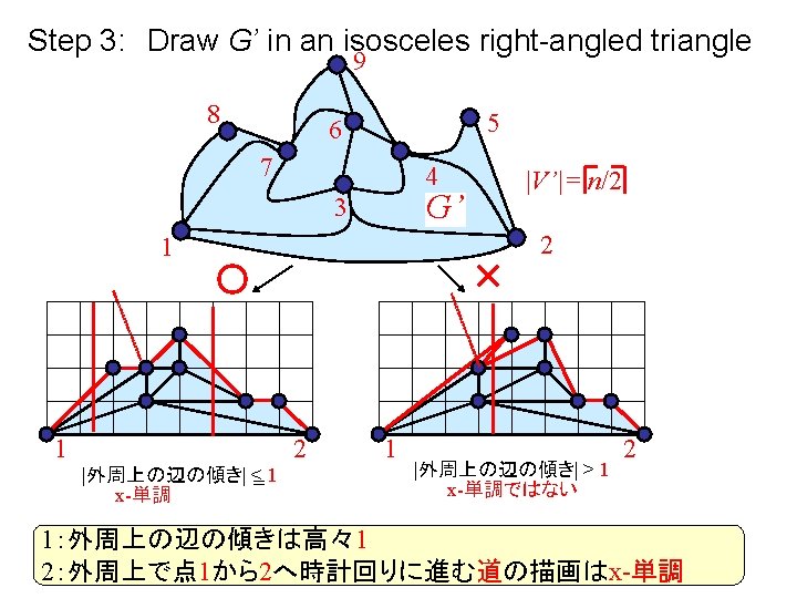
Step 3: Draw G’ in an isosceles right-angled triangle 9 8 5 6 7 G 4 G’ 3 |V’|= n/2 2 1 W/2 1 W= < n/2 -1 |slope| = <1 2 |slope| > 1
The drawing of the path passing through all k’s neighbors is “weakly convex” k not “weakly convex”
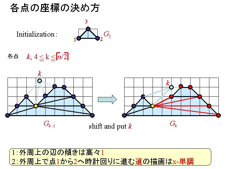
The rightmost neighbor of k is higher than the leftmost neighbor Case 1:k has exactly one highest neighbor k Gk -1 shift and put k k Gk
The rightmost neighbor of k is higher than the leftmost neighbor Case 2:k has exactly two or more highest neighbor k Gk -1 k shift and put k Gk
Drawing of G’ 3 1 G 3 2
Drawing of G’ shift
Drawing of G’ +4
Drawing of G’ shift
Drawing of G’ +5
Drawing of G’ shift
Drawing of G’ +6
Drawing of G’ shift
Drawing of G’ +7
Drawing of G’ shift
Drawing of G’ +8
Drawing of G’ shift
Drawing of G’ +9
Drawing of G’ G’ H’ <W’/2=( n/2 -1) = W’ = < n/2 -1 Shift one time for each vertex 2
Step 5: Combine the drawing of G’ and G” G” W/2 1 G’ W= < n/2 -1 W/2
Step 5: Combine the drawing of G’ and G” G” W/2 |辺の傾き|>1 G’ W= < n/2 -1 |外周上の辺の傾き| <= 1 1 W/2
Step 5: Combine the drawing of G’ and G” G” |辺の傾き|>1 G’ |外周上の辺の傾き| <= 1
Step 5: Combine the drawing of G’ and G” G” G’ x-単調
Step 5: Combine the drawing of G’ and G” G G” W/2 1 G’ W= < n/2 -1 H< = n/2 W< = n/2 -1
Miura et al. ‘ 01 Input: 4 -connected plane graph G Output: a straight line grid drawing < n-1) Grid Size : (W +H = W= < n/2 -1, H = < n/2 2 Area: W x H < (n -1) = 2 H< = n/2 W= < n/2 -1 The algorithm is best possible H = n/2 W = n/2 -1
Objective i h g 9 bends f e a g f h i e d d c b a b c 4 bends an orthogonal drawing with the minimum number of bends. To minimize the number of bends in an orthogonal drawing.