AUXILIARY VIEWS Creating Special Orthographic Views Introduction l


- Slides: 9

AUXILIARY VIEWS Creating Special Orthographic Views

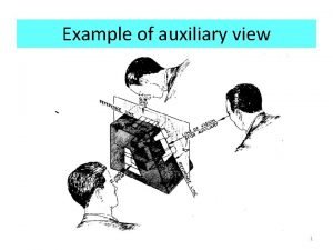
Introduction l We know there are 3 principal views in a Multiview Drawing, Front, Top and Right Views. However, to solve problems involving inclined (slanted) surfaces, you will need to learn to draw views on auxiliary (additional) planes of projection. These are called auxiliary views.

AUXILIARY VIEWS ARE "HELPER VIEWS" l When an object has inclined surfaces, these do not show up in true shape or size in regular views. However, a view on a plane parallel to the inclined surface does show its true size and shape. This is an auxiliary view. It, along with the other regular views describe the object better. Regular Views with Auxiliary View

Why Do We Use Them? l l An auxiliary view is a projection on an auxiliary plane that is parallel to an inclined (slanting) surface. It is a view looking directly at the inclined surface in a direction perpendicular to it. Auxiliary projections are important for describing the true geometric shapes of inclined surfaces. You also use them for dimensioning these shapes.

How to Draw an Auxiliary View Using the Center Plane Reference l In diagram A, (to the left) the object is shown in an isometric view. Because the object is symmetrical, you use a center plane as a reference plane, to make the auxiliary view using the following steps.

How to Draw an Auxiliary View Using the Center Plane Reference l Diagram B shows you use a center plane as a reference plane, (center plane construction). The edge view of this plane appears as a centerline, line XY, on the top view. Number the intersection points on the top view. Then transfer these numbers to the edge view of the inclined surface on the front view, as shown.

How to Draw an Auxiliary View Using the Center Plane Reference l Parallel to this edge view of the angled surface and at a convenient distance from it, draw the line X'Y', as shown in Diagram C to the left.

How to Draw an Auxiliary View Using the Center Plane Reference l Now, in the top view, find the distances (D 1 & D 2) from the numbered points to the centerline. These are the depth measurement. Transfer them onto the corresponding construction lines (gold color) that you have just drawn, measuring them off on either side of line X’Y’ as shown in Diagram D.

How to Draw an Auxiliary View Using the Center Plane Reference l Connect and number these points as in Diagram E and you will have the auxiliary view of the inclined surface.
