Sections of Solids ME 111 Engineering Drawing Sectional


- Slides: 13
Sections of Solids ME 111 Engineering Drawing
Sectional Views • The internal hidden details of the object are shown in orthographic views by dashed lines. • The intensity of dashed lines in orthographic views depends on the complexity of internal structure of the object. • If there are many hidden lines, it is difficult to visualize the shape of the object – unnecessarily complicated and confusing. • Therefore, the general practice is to draw sectional views for complex objects in addition to or instead of simple orthographic views. • A sectional view, as the name suggests, is obtained by taking the section of the object along a particular plane. An imaginary cutting plane is used to obtain the section of the object.
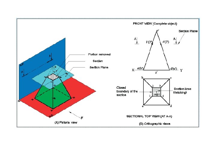
Theory of Sectioning • Whenever a section plane cuts a solid, it intersects (and or coincides with) the edges of the solids. • The point at which the section plane intersects an edge of the solid is called the point of intersection (POI). • In case of the solids having a curved surface, viz. , cylinder, cone and sphere, POIs are located between the cutting plane and the lateral lines.
True Shape of Sections • A section will show its true shape when viewed in normal direction. • To find the true shape of a section, it must be projected on a plane parallel to the section plane. • For polyhedra, the true shape of the section depends on the number of POIs. The shape of the section will be a polygon of the sides equal to the number of POIs. • The true shape of the section of a sphere is always a circle. • The sections of prisms and pyramids are straight line segmented curves. • The sections of cylinders and cones will mostly have smooth curves.
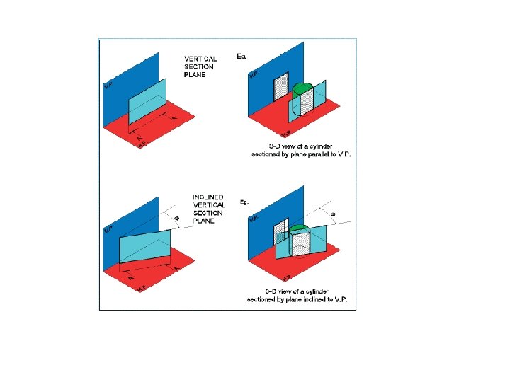
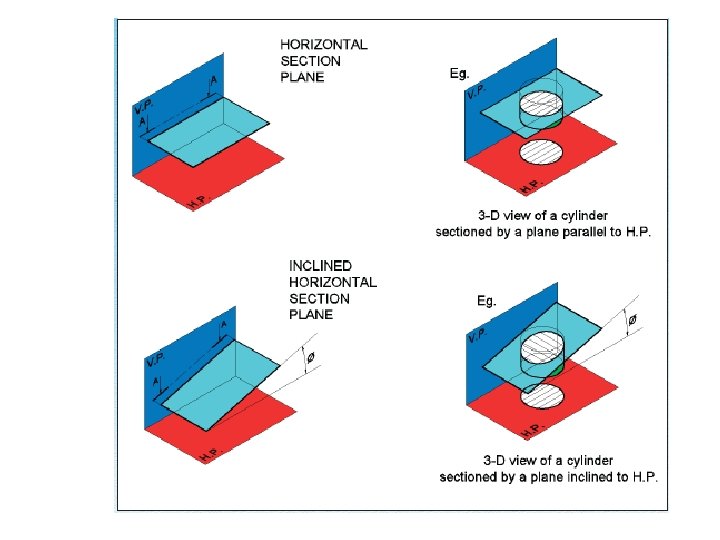
Types of Cutting Planes and Their Representation • A cutting plane is represented by a cutting plane line • The cutting plane line indicates the line view of the cutting plane. • The two ends of the cutting plane line are made slightly thicker and provided with arrows. • The direction of the arrow indicates the direction of viewing of the object. • In the first-angle method of projection, the direction of the arrows is toward the POP, i. e. , toward XY (or X 1 Y 1). • Types of section planes • Vertical Section plane • Horizontal Section Plane • Profile Section plane • Auxiliary Section plane • Oblique Section plane
Hatching of the Sections • The surface created by cutting the object by a section plane is called as section. • The section is indicated by drawing the hatching lines (section lines) within the sectioned area. • The hatching lines are drawn at 45° to the principal outlines or the lines of symmetry of the section • The spacing between hatching lines should be uniform and in proportion to the size of the section. 2 H H or HB
SECTIONAL VIEW – PARALLEL TO H. P AND PERPENDICULAR TO V. P A cube of 40 mm sideis cut by a horizontal section plane, parallel to H. P at a distance of 15 mm from the top end. Draw the sectional top view and front view
A cone of diameter 60 mm and height 60 mm is resting on HP on one of its generators. A section plane whose VT is parallel to HP and 15 mm above HP, cuts the solid removing the top portion. Draw the front view and sectional top view of the solid. O’ 4 2 3 Assume cone is resting on HP 61 f 71 81 d 11 51 41 d’ b’ e’ c’ a’ O’ Φ 60 5 7’ O 1 5’ 1’ 2’, 8’ 3’, 7’ 4’, 6’ 5’ 7 8 6 4’, 6’ X f’ g’ 1’ 2 ’, 8 ’ 3’, 60 g 21 c a e 15 O 1 b 31 Tilt cone about its corner Y
A pentagonal prism , 30 mm base side & 50 mm axis is standing on Hp on it’s base whose one side is perpendicular to Vp. It is cut by a section plane 450 inclined to Hp, through mid point of axis. Draw Fv, sec. Tv & sec. Side view. Also draw true shape of section C E AP TR SH E U B D A Y 1 E ’ d” d c’ X 1 b’ e’ b” e” a’ c” a” X e d For True Shape: a Draw x 1 y 1 // to sec. plane Draw projectors on it from cut points. Mark distances of points of Sectioned part from Tv, on above projectors from x 1 y 1 and join in sequence. Draw section lines in it. It is required true shape. c b Y Solution Steps: for sectional views: Draw three views of standing prism. Locate sec. plane in Fv as described. Project points where edges are getting Cut on Tv & Sv as shown in illustration. Join those points in sequence and show Section lines in it. Make remaining part of solid dark.
A Cone base 75 mm diameter and axis 80 mm long is resting on its base on H. P. It is cut by a section plane perpendicular to the V. P. , inclined at 45º to the H. P. and cutting the axis at a point 35 mm from the apex. Draw the front view, sectional top view, sectional side view and true shape of the section. (LAB QUESTION : COMMON) c 1 h 1 d 1 g 1 f 1 e 1 X 1 o” l 1 a 1 d’ j’ c’ k’ 4 10 c d b 6 8 7 6 e f g 7 h 11 i k 8 j 10 4” 5” 3” 5 o l h” i” e” 5 9 4 a 12 g” d” j” c” k” l” a” 3 1 f” b” 2 3 1 12 11 2 g’ f’ e’ h’ i’ b’ l’ a’ X 35 k 1 j 1 b 1 i 1 o’ 9 Y 1 6” 2” 7” 1” 8” 9” 10” 12” 11” Y