Track Parameters for track monitoring including Various Track


 • Track has to be laid to desired standards")

 Translational along X axis Shuttling Loose")


 99. 7% 95 % 68% σ 2σ 3σ")


 • Due to wide variety of rolling stock")

 For comparing")

 • Planned Maintenance (PML) •")
 • Ref. -Para 520 (1) • To be measured")
 Ref. -Para 520 (2) (a) & (b) • For Unevenness")
 Tolerances • Planned Maintenance (PML) under Loaded •")
 Ref. - Para 521 (a) • To act as")
 Prior to ACS 149 Ref- Para 522 (1), (2),")
 • Planned Maintenance (PML) •")
 Limit (NBML) • Act as reference for Need")
, (2), (3), (4) ) SD")
 Ref- Para 522 (1), (2), (3), (4) Peak")
 • Planned Maintenance (PML) •")
 • • • Ref- Para 521(c) These limits are")
 Ref- Para 522 (1), (2), (3), (4) Prior to")
, Planned Maintenance (PML),")
 (a) & (b) and Para 522 (1),")
 (a) & (b) and Para 522 (1),")
 Ref. -Para 520 (2) (a) & (b) and Para 522")
 (a) & (b) Twist (Tw-1) in mm/M")
, Planned Maintenance (PML),")
 (a) & (b) and Para")


 (a) & (b) and Para 522")

 CHORD Twist (TW-1) UML Twist (TW-1)")


-(f) of IRTMM • Peak Value, No Speed Band,")


- Slides: 78
Track Parameters for track monitoring including Various Track Tolerances Periods 6 1
Track • The main function of track is to transfer train loads to the formation and provide guide path • Safety • Permits safe negotiation by rolling stock • Comfortable Ride • Should not to cause undesirable acceleration 2
Track Quality • Track Performance is judged by Riding comfort, which depends on • Track Geometry parameters • Vehicle Design parameters • Speed of Operation • What are we concerned with? • Track defects which are causing the undesirable accelerations
Track STANDARDS (LAYING & Maintenance) • Track has to be laid to desired standards & then maintained; not only for • Good riding comfort and Safety, But also for Longer life of asset. • Quality control is essential while laying new track & subsequently for checking effectiveness of maintenance operations. • The maintenance operation should be need based rather than periodic in any Good system. 4
Track Tolerances –various defects • Gauge Defect Variation in distance between two rails from standard distance of 1676 mm (Nominal gauge) • Cross Level (Cant) Change in difference of level of two rails at specified Location • Twist =Y/L Y= Tb 1 -Ta 1 Unevenness Rail irregularity in vertical plane • Alignment Rail irregularity in horizontal plane • Twist Change in difference of level of two rails of Track at specified distance Y L 5
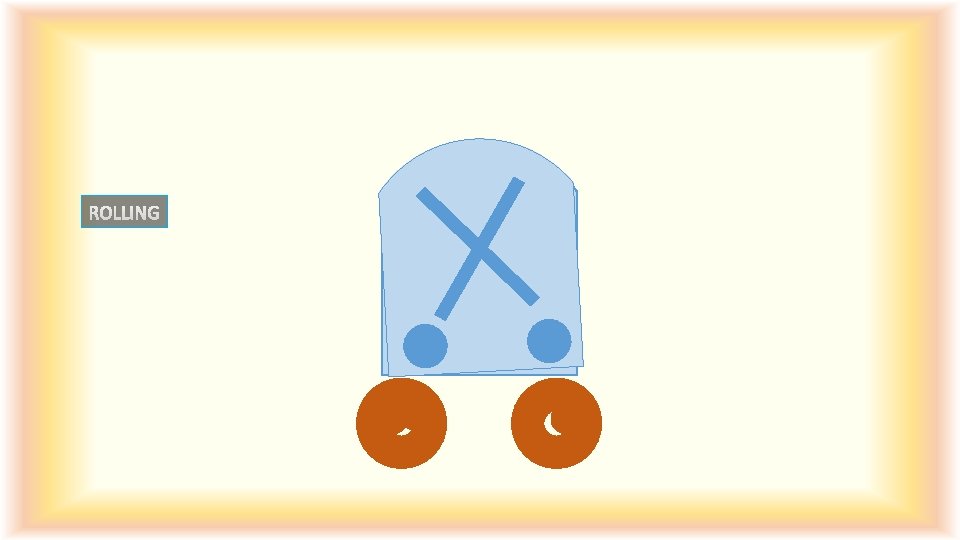
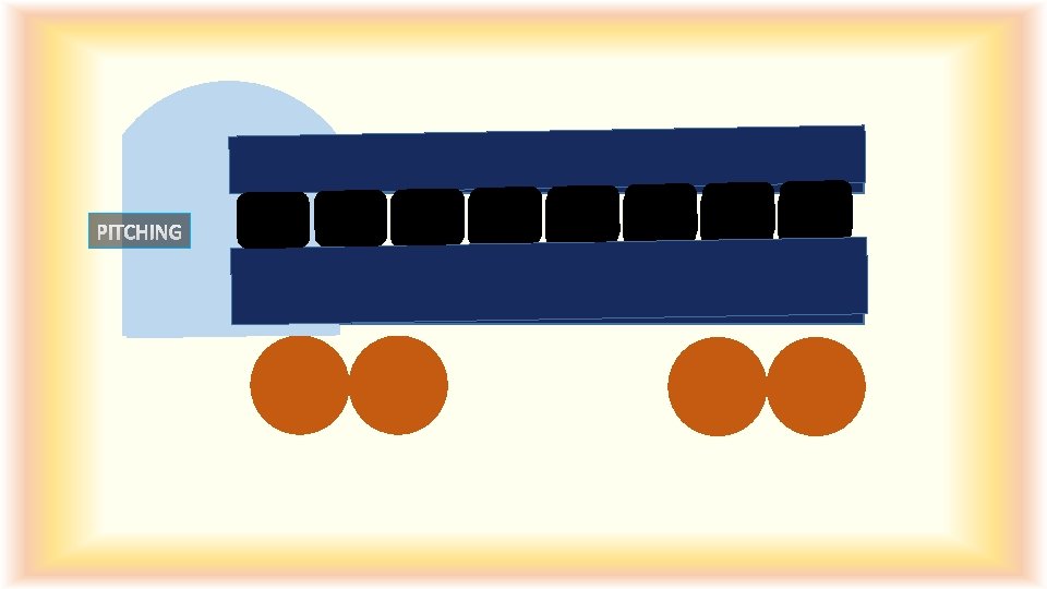
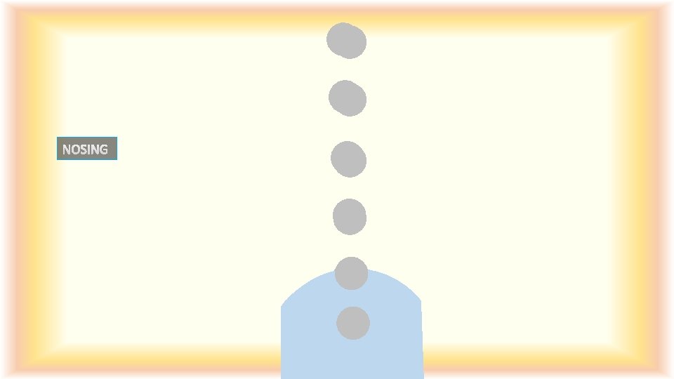
Nomenclature of Movements Sl. no Movement Nomenclature A) Translational along X axis Shuttling Loose shunting Caused by B) Translational along Y axis Lurching Alignment defect including gauge variations. C) Translatonal along Z axis Bouncing Unevenness of rail top D) Rotational about X axis Rolling Cross level/ unevenness E) Rotational about Y axis Pitching Unevenness F) Rotational about Z axis Nosing Alignment defect Hunting- Combined Effect of Rolling and Nosing
Y A X I S X AXIS Z A X IS X AXIS Z Y A X I S
X AXIS
Y A X I S
Z A X IS Z A
Ride Quality Correlation: Between Track Parameters & Ride quality Unevenness Vs Vertical Acceleration Vs Vertical Ride Index Vs Off-Loading & On-Loading Alignment Vs Lateral Acceleration Vs Lateral Ride Index Vs Lateral Force Twist Vs Off-Loading 15
Objective of Measurement • Measuring track parameters or Performance • To identify the deviations or the defects • To compare the existing track parameters with the standard/desired track parameters. • To monitor the rate of deterioration for special attention • To give timely input and prolong the life of the asset • To assess the quality of track maintenance inputs
Objectives of Track Recording and Tolerances Safe, Comfortable And Economical Transportation Optimal Use Of Maintenance Inputs To Track WHEN To Know Where Maintenance Inputs Are Required Monitoring Of Track Quality And Performance 17
METHOD OF INSPECTION • • FOOT INSPECTION. PUSH TROLLEY/MOTOR TROLLEY. FOOT PLATE/REAR WINDOW. TRACK MONITORING EQUIPMENTS. PURPOSE OF MANUAL INSPECTION • • Inspection of track structure. Inspection of Gang working. Field verification of track defects. Inspection of other track related items.
Manual System of Measurement • Manual Inspection • Push Trolley / Foot Inspections • Foot Plate and Brake Van Inspections • Manual Measurements • Measurement of Track parameters i. e. Unevenness, Alignment, Twist by measuring Cross Level, Gauge • Assessment of Lateral or Vertical Jerks
Limitations of Manual Measurement • • • Subjective - Depends upon Human Response Track parameters in Floating Condition only Time Consuming- Slow and Tiring No Continuous record of Track Geometry Not amenable to detailed analysis Inappropriate for Modern Track Structure and Mechanized Maintenance
Mechanised Measurement For objective assessment of track quality the following mechanized means are being used on Indian Railways. Ø Track Recording Cars (TRC) – TMM directorate of RDSO – Engineering Department Ø Oscillograph Cars – Mechanical Directorate of RDSO Ø Oscillation Monitoring System (OMS) – Divisions or Zonal Headquarters
Advantage of Mechanised Measurement • Objective assessment • Measurement in Loaded Condition • Systematic recording and analysis of data • Fast and convenient • Continuous record of track parameters • Less Human Intervention
Presentation of Measurements • Peak Based ØIt helps in identifying isolated localized defects ØFor Isolated attentions • Standard Deviation (SD) Based ØIt helps in identifying bad stretch ØIt is useful in deciding machine maintenance
Standard Deviation • The bell curve may be steep or flat depending on the spread of the data; • Steep- Less value of SD • Flat - More value of SD
SDSAMPLE Station 1 2 3 4 5 6 7 8 9 10 11 12 13 14 15 16 17 18 19 20 G 0 5 3 -3 0 3 -2 0 0 -3 0 3 -3 1 3 -3 0 3 2 0 Average(μ) 0. 45 ∑(x−μ)^2 σ=√{∑(x−μ)^2 /N} (x−μ)^2 0. 20 20. 70 6. 50 11. 90 0. 20 6. 50 6. 00 0. 20 11. 90 0. 20 6. 50 11. 90 0. 30 6. 50 11. 90 0. 20 6. 50 2. 40 0. 20 G 15 5 3 -3 0 3 -2 0 -15 -3 0 3 -3 1 3 -3 0 3 2 0 (x−μ)^2 211. 70 20. 70 6. 50 11. 90 0. 20 6. 50 6. 00 0. 20 238. 70 11. 90 0. 20 6. 50 11. 90 0. 30 6. 50 11. 90 0. 20 6. 50 2. 40 0. 20 0. 45 110. 9 338. 2 2. 35 4. 11 25
Significance of Standard Deviation ( σ) 99. 7% 95 % 68% σ 2σ 3σ One σ away from the mean in either direction on the horizontal axis (the red area on the above graph) accounts for about 68 percent of the data in this group. Two σ away from the mean (the red and green areas) account for roughly 95 percent of the data. Three σ (the red, green and blue areas) account for about 99 percent of the data.
PERCENTILE Q 1 - 8*100/32=25 Percentile i. e. 28, Q 2 - 16*100/32=50 Percentile i. e. 27 29. 9
Standard Deviation BASED and Peak Based Assessment • SD based Measurement takes into account magnitude of each and every data of vehicle ride while Peak based Measurement indicates no. of peaks exceeding a limit without giving an idea of magnitude of various peaks • Peak based Measurement facilitates isolated attention but deployment of machine over long stretches can not be decided. • More value of SD for any parameter indicates more variation and less uniform track profile. • Less value of SD for any parameter indicates less variation and more uniform track profile. • Uniform track profile results in better riding quality
Why Track Tolerances ? • Ideal Conditions cannot be kept while laying new track & subsequently during maintenance, so some range is required • To limit the disturbance in service • For Monitoring • To appreciate and control quality • For optimization of Maintenance Resources and maintenance cycle • To avoid Subjectivity • To optimize safety and Comfort Worthiness of Track 29
Track Tolerances - how? • Economy in Maintainability duly Maintaining Safety & Comfort– • Touch the Track only when required and where required, • To ensure Objective Decision making and Plan maintenance interventions accordingly • For Tolerances under Loaded Condition – • Statistical Analysis done for Standard Deviation and Peak Based tolerances under NTL, PML & NBML • By drawing CFD defect wise, as per TRC Data of IR spread over more than 20000 Km (25 sections for Speed band <=100 Kmph, 36 sections for Speed band >100&<=110 Kmph, 32 sections for Speed band >110 Kmph&<=130 Kmph, 4 sections for Speed band >130 Kmph&<=160 Kmph) 30 • Regression Analysis to establish scientific correlation between SD
4. 60 3. 40 1. 40 2. 00 1. 00 5. 75 4. 20 2. 40 2. 30 5. 40 1. 35 31
32
Change in Chord Lengths Ref- Para 508 of irpwm- Letter no. 2007/TRACK-III/TK/7 dt. 11. 4. 14 New Chords for Tolerances under Loaded Condition SN Parameter 1 Unevenness 2 Alignment 3 Short Chord / Base 9. 0 m (UN-1) 9. 0 m (AL-1) Twist Reasons- 3. 0 m (TW-1) For Goods Stock Long Chord/ Base 18. 0 m (UN-2) 15. 0 m (AL-2) 15. 0 m (TW-2)For RDSO Only No Tolerance For Coaching Stock Improved suspension system in Existing and New rolling stock, Increase in Speed potential & Chord used in track machines varies from 14. 65 to 18. 4 meter Previous Chords for Tolerances under SN Parameter Short Chord/ Base Long Chord/ Base 1 Unevenness 3. 6 m 9. 6 m 2 Alignment 7. 2 m 9. 6 m 3 Twist 3. 6 m 4. 8 m 33
Short Chord and Long Chord (TM-11) • Due to wide variety of rolling stock on IR • Control over wide wave band of track irregularities is required. • Rolling stocks having stiff suspension respond to short wave length (λ) irregularities. • Four wheelers and bogie freight wagons. • Rolling stocks having softer suspension respond to long wave length (λ) irregularities. • Passenger coaches and locomotives. 34
Critical Wavelengths 35
Track Tolerances – BASED ON MEASUREMENT METHODS Tolerances under Loaded Condition (IRPWM) For comparing the Track defects recorded mechanically (TRC/ OMS/Oscillograph ) under load Tolerances under Floating Condition (IRPWM) Tolerances for Machine Maintenance (IRTMM) Standard Deviation Based Helps in identifying bad stretch (i. e. TRC block) Useful in deciding Machine Maintenance and Spot attentions Peak Based (Approx. 3*SD Based) Helps in identifying Isolated & Localised Defects Used for Isolated Attentions For comparing the track parameters recorded manually during various Inspections without load Isolated Defect To be Measured by the Recorder available with Machine after Tamping Operation for checking quality of Tamping Work 36
Track Tolerances- How many? Tolerance s under Loaded Condition Tolerance s under Floating Condition • New Track Tolerance (NTL) Track-III/TK/7 dated 12 -07 -07 • Planned Maintenance (PML) • Priority II (Service Tolerance or • Need Based Maintenance Planned Maintenance) (NBML) • Priority I (Index Tolerance or Urgent • Urgent Maintenance (UML) Maintenance) TM-109 vide Letter No. 2007/ • New Track • Existing track • Tolerance for Realignment of Curve • Slowdown Tolerance for Worksites/ Yard lines etc Tolerances For Machine Maintenance • Tamping Tolerance 37
Tolerances under Loaded Condition • New Track Tolerance (NTL) • Planned Maintenance (PML) • Need Based Maintenance (NBML) • Urgent Maintenance (UML)
New Track Tolerance LIMIT (ntl) • Ref. -Para 520 (1) • To be measured three months after speed is raised to normal • Track parameters Limits for a Best quality track • To act as reference for Quality Control of Track Renewal, Track Laying Works • Highest level of geometrical parameter of track that can be achieved on a new or relayed track with new material • Nicely laid track results in lesser maintenance inputs & longer life of track assets besides resulting in Safety and Comfort 39
New Track Tolerances (NTL) Ref. -Para 520 (2) (a) & (b) • For Unevenness & Alignment only, both SD and Peak Based • No Tolerances for Gauge and Twist • For Two Speed Bands <= 100 Kmph & > 100 Kmph upto 160 kmph • Limits for alignment of curve are variation w. r. t. Design versine Speed <= 100 Kmph SN Parameter SD Based Peak based 2. 0 mm 6. 0 mm Speed > 100 Kmph and <= 160 kmph SD Based 1. 4 mm Peak based 4 mm 1. UN-1 2. UN-2 XX XX 1. 9 mm 6 mm 3. AL-1 1. 4 mm 1. 1 mm 3 mm 4. AL-2 XX XX 1. 3 mm 40
• New Track Tolerance (NTL) Tolerances • Planned Maintenance (PML) under Loaded • Need Based Maintenance Condition (NBML) • Urgent Maintenance (UML)
Planned Maintenance Limit (PML ) Ref. - Para 521 (a) • To act as reference & guidance for Planned maintenance of Complete Block section • PML are only for Unevenness and Alignment which affect Ride quality; • No limits for Gauge & Twist • Based on Standard Deviation (SD) values and not Peak based • In case of curve, the limits for alignment are above average versine • For Four Speed bands Ref: - Para 523 (3) -RDSO Letter No. TM/IM/9 dated 27. 04. 20 • The blocks requiring planned maintenance on the basis of laid down SD based PML shall be identified for block sections and for yards separately using off line software or through TMS. • In case recorded SD of defect exceeds these limits for more than 40% of track in block section or 50% of track in Yard • Block Section means Any main Line from TRC Block of Last SEJ of preceding station (Excluding) to First SEJ of this station (Excluding) • Yard means- Between Two block Section 42
Planned Maintenance Limit ( PML) Prior to ACS 149 Ref- Para 522 (1), (2), (3), (4) Speed SN Parameter <= 100 Kmph >100 Kmph & <= 110 Kmph >110 Kmph & <= 130 Kmph >130 Kmph & <= 160 Kmph 1. 0 Unevenness (SD Based) 1. 1 UN-1 5. 0 3. 8 3. 3 2. 9 1. 2 UN-2 XX 5. 4 5. 1 4. 4 2. 0 Alignment (SD Based) 2. 1 AL-1 3. 3 2. 5 1. 9 2. 2 AL-2 XX 4. 1 3. 5 2. 5 3. 0 Gauge XX XX 4. 0 Twist XX XX 43
Tolerances under Loaded Condition • New Track Tolerance (NTL) • Planned Maintenance (PML) • Need Based Maintenance (NBML) • Urgent Maintenance (UML)
Need Based Maintenance Ref- Para 521(b) Limit (NBML) • Act as reference for Need Based maintenance of blocks of 200 m Track for applying timely correction before the defects size grows to the level of UML; requiring traffic slow down. • Allowable time for attention depend upon the magnitude of the defects and also on Sectional Speed, Axle Load, Traffic Volume, Wear & Tear etc. • For Unevenness and Alignment - based both on Standard Deviation and Peak Values. • For Gauge and Twist - based on Peak Values • In case of curve, the limits for alignment are above average versine • Four Speed Bands Ref: - Para 523 (2) -RDSO Letter No. TM/IM/9 dated 27. 04. 20 • The blocks requiring Need Based Maintenance on the basis of laid down SD based NBML and isolated spots on the basis of laid down Peak based NBML shall be identified using offline software or through TMS. • If the Gap between two NBML locations is <= 200 M, then Gap should also be attended during 45 NBML attention
Need Based Maintenance Limit (NBML Ref- Para 522 (1), (2), (3), (4) ) SD & Peak Based Tolerances for Unevenness and Alignment in Four Speed Bands Speed SN Parameter <= 100 Kmph Unevenne ss SD UN-1 6. 8 mm 20 mm 1. 2 UN-2 2 Alignment XX SD XX Peak 2. 1 4. 9 mm 1 1. 1 AL-1 Peak 15 mm >100 Kmph & <= >110 Kmph & <= >130 Kmph & <= 110 Kmph 130 Kmph 160 Kmph SD 5. 5 mm 7. 5 SD mm 3. 9 mm 6. 7 Peak SD Peak 17 mm 4. 9 mm 15 mm 4. 4 mm 13 mm 23 mm 7. 4 mm 22 mm 6. 6 mm 20 mm Peak SD Peak 12 mm 3. 6 mm 11 mm 46
Need Based Maintenance Limit (NBML ) Ref- Para 522 (1), (2), (3), (4) Peak Based Tolerance for Block wise Average Gauge, Isolated Gauge and Twist in Four Speed Bands SN 3 Parameter Speed <= 100 >100 and <= >110 & <= >130 & <= 160 Kmph 110 Kmph 130 Kmph Gauge 3. 1 Mean gauge over 200 m section (One TRC Block) over nominal gauge -6 mm to +10 (a) Straight -8 mm to +10 mm mm -5 mm to +13 (b) Curve with radius 440 m or more -5 mm to +14 mm mm 3. 2 Isolated defects –Nominal track gauge to peak value -5 mm to +18 (c) Curve with radius less than 440 m -5 mm to +18 mm -8 mm to +12 mm (a) Straight -10 mm to +12 mm mm -6 mm to +16 (b) Curve with radius 440 m or more -7 mm to +17 mm mm 4. Twist (TW-1) 5 mm/m 4 mm/m 3. 5 mm/m 47
Tolerances under Loaded Condition • New Track Tolerance (NTL) • Planned Maintenance (PML) • Need Based Maintenance (NBML) • Urgent Maintenance (UML)
Urgent Maintenance Limits (UML ) • • • Ref- Para 521(c) These limits are so specified that upon their exceedances, the permitted speed should be reduced; which can be restored only after attending the track In case of acceleration peak exceeding the UML for a speed band, the permitted speed should be reduced to a lower speed level keeping in view the aforesaid criteria and be restored only after attending the track Peak Based Tolerance for Block wise Average Gauge, Isolated Gauge and Twist Limit for Lateral & vertical Acceleration on comfort consideration , Four Speed Bands 49
Urgent Maintenance Limits ( UML) Ref- Para 522 (1), (2), (3), (4) Prior to ACS 149 Peak Based Tolerance for Vertical & Lateral acceleration, Block wise Average Gauge, Isolated Gauge & Twist, Four Speed Bands SN Parameter <= 100 Kmph >100 & <= 110 Kmph Speed >110 & <= 130 Kmph >130 & <= 160 Kmph 1 Vertical And Lateral Acceleration 0. 30 g 0. 25 g 0. 20 g Peak 2 3 Gauge 3. 1 Mean gauge over 200 m section (One TRC Block) over nominal gauge (a) Straight -10 mm to + 12 mm -8 mm to + 12 mm (b) Curve with radius 440 m or more -7 mm to +17 mm (c) 3. 2 (a) (b) (c) Curve with radius less than 440 m -7 mm to +20 mm Isolated defects –Nominal track gauge to peak value Straight -12 mm to + 15 mm Curve with radius 440 m or more -11 mm to +20 mm Curve with radius less than 440 m -8 mm to +25 mm 4. Twist (TW-1) 7 mm/m 6 mm/m -7 mm to +15 mm -7 mm to +20 mm -10 mm to + 15 mm -9 mm to +20 mm -8 mm to +25 mm/m 50
All Tolerances under Loaded Condition i. e. New Track Tolerance (NTL), Planned Maintenance (PML), Need Based Maintenance (NBML), Urgent Maintenance (UML) For All Speed bands
Tolerances - unevenness Ref. -Para 520 (2) (a) & (b) and Para 522 (1), (2), (3), (4) of IRpw. M Unevenness UN-1 (In mm) < = 100 Kmph NTL SD PEAK 2. 0 6. 0 PML SD PEAK 5. 0 XX NBML SD PEAK 6. 8 20 >100 & < = 110 Kmph >110 & < = 130 Kmph 1. 4 4. 0 3. 8 3. 3 XX XX 5. 5 4. 9 17 15 >130 & < = 160 Kmph 1. 4 4. 0 2. 9 XX 4. 4 13 UN-2 (In mm) < = 100 Kmph SD XX PEAK XX >100 & < = 110 Kmph >110 & < = 130 Kmph 1. 9 6. 0 5. 4 5. 1 XX XX 7. 5 7. 4 23 22 >130 & < = 160 Kmph 1. 9 6. 0 4. 4 XX 6. 6 20
Tolerances - ALIGNMENT Ref. -Para 520 (2) (a) & (b) and Para 522 (1), (2), (3), (4) of IRpw. M Alignment AL-1 (In mm) < = 100 Kmph NTL SD PEAK 1. 4 4. 0 PML SD PEAK 3. 3 XX NBML SD PEAK 4. 9 15 >100 & < = 110 Kmph >110 & < = 130 Kmph 1. 1 3. 0 2. 5 XX XX 3. 9 3. 6 12 11 >130 & < = 160 Kmph 1. 1 3. 0 1. 9 XX 3. 6 11 AL-2 (In mm) < = 100 Kmph SD XX PEAK XX >100 & < = 110 Kmph >110 & < = 130 Kmph 1. 3 4. 0 4. 1 3. 5 XX XX 6. 7 5. 3 20 16 >130 & < = 160 Kmph 1. 3 4. 0 2. 5 XX 4. 9 15
Tolerances – Gauge (Peak) Ref. -Para 520 (2) (a) & (b) and Para 522 (1), (2), (3), (4) of IRpw. M Mean Gauge over 200 M (In mm) NTL xx Straight <= Curve with radius 440 m or xx 130 more Kmph Curve with radius less than 440 xx Straight xx m 440 m or >130 Curve with radius xx more &< = 160 Curve with radius less than 440 Isolated Gauge (In mm) NTL xx m xx Straight <= Curve with radius 440 m or xx 130 more Kmph Curve with radius less than 440 xx Straight xx m 440 m or >130 Curve with radius xx more &< = PML NBML UML xx -8 to +10 -10 to +12 xx -5 to +14 -7 to +17 xx xx -6 to +10 -5 to +18 -8 to +12 -7 to +20 xx -5 to +13 -7 to +15 PML xx -5 NBML to +18 -7 UML to +20 xx -10 to +12 -12 to +15 xx -7 to +17 -11 to +20 xx xx -8 to +12 -6 to +22 -10 to +15 -8 to +25 xx -6 to +16 -9 to +20
Tolerances - TWIST Ref. -Para 520 (2) (a) & (b) Twist (Tw-1) in mm/M NTL XX < = 100 Kmph XX >100 & < = 110 Kmph XX >110 & < = 130 Kmph XX >130 & < = 160 Kmph and Para 522 (1), (2), (3), (4) of IRpw. M PML NBML UML XX 5 (15 mm) 7 (21 mm) XX 4 (12 mm) 6 (18 mm) XX 3. 5 (10. 5 mm) 5 (15 mm) Tolerances - ACCleration Ref. - Para 522 (1), (2), (3), (4) of IRpw. M Acceleration (V &L) NTL PML NBML XX XX XX < = 110 Kmph XX XX XX >110 & < = 130 Kmph XX XX XX >130 & < = 160 Kmph UML 0. 30 g 0. 25 g 0. 20 g
All Tolerances under Loaded Condition i. e. New Track Tolerance (NTL), Planned Maintenance (PML), Need Based Maintenance (NBML), Urgent Maintenance (UML) For Speed band >100 Kmph & <=110 Kmph
Tolerances - unevenness & alignment Ref. -Para 520 (2) (a) & (b) and Para 522 (2) of IRpw. M Speed > 100 < = 110 Kmph NTL SN Parameter 1 Unevennes s 1. 1 UN-1 1. 2 UN-2 NBML PEAK SD PEAK 1. 4 mm 3. 8 mm XX 5. 5 mm 1. 9 mm 6 mm 5. 4 mm XX 17 mm 7. 5 mm 23 mm 1. 1 mm 3 mm 2. 5 mm XX 1. 3 mm 4. 1 mm XX 3. 9 mm 12 mm 6. 7 mm 20 mm SD PEAK SD 2 Alignment 2. 1 AL-1 2. 2 AL-2 UML PEAK (Accn. ) Vertical and Lateral Acceleration 0. 30 g 57
UN-2 NTL >100<=110 SPEED BAND IN KMPH UN-2 PML UN-2 NBML , 7. 5 UN-1 NBML UN-2 PML , 5. 4 UN-2 NTL , 1. 9 UN-1 PML UN-1 NBML , 5. 5 UN-1 NTL UN-1 PML , 3. 8 UN-1 NTL , 1. 4 0 0. 5 1 1. 5 2 2. 5 3 3. 5 4 4. 5 5 5. 5 6 6. 5 7 7. 5 UNEVENNESS TOLERANCE IN mm SD - UNEVENNESS ON 9. 0 M (UN-1) & 18. 0 M(UN-2) CHORD UN-2 NBML
SPEED BAND IN KMPH >100<=110 AL-2 NBML , 6. 7 AL-2 PML , 4. 1 AL-2 NTL , 1. 3 AL-1 NBML , 3. 9 AL-1 PML , 2. 5 AL-1 NTL , 1. 1 0 0. 5 1 1. 5 2 2. 5 3 3. 5 4 4. 5 5 5. 5 6 6. 5 7 ALIGNMENT TOLERANCE IN mm SD - ALIGNMENT ON 9. 0 M (AL-1) AND 15. 0 M(AL-2) CHORD AL-1 NTL AL-1 PML AL-1 NBML AL-2 NTL AL-2 PML AL-2 NBML
Tolerances – gauge &twist Ref. -Para 520 (2) (a) & (b) and Para 522 (2) of IRpw. M Speed > 100 < = 110 Kmph SN Parameter NTL PML Gauge 3. 1 Mean Gauge over 200 M section (One TRC Block) over Nominal gauge XX A Straight XX XX B Curve-R > 440 XX XX C Curve-R < 440 XX NBML UML -8 to +10 mm -10 to +12 mm -5 to +14 mm -7 to +17 mm -5 to +18 mm -7 to +20 mm -10 to +12 mm -12 to +15 mm -7 to +17 mm -8 to +25 mm 3 3. 2 Isolated defects –Nominal Track Gauge to Peak XX A Straight XX B Curve-R > 440 XX XX C Curve-R < 440 XX XX 4. Twist(TW-1) XX XX -6 to +22 mm -11 to +20 mm 60 7 mm/M
NBML-ST NBML-R>=440 m NBML-R<440 m UML-ST UML-R>=440 m UML-R<440 m 6 9 12 15 18 21 24 27 NBML-ST >100<=110 SPEED BAND IN KMPH UML-R<440 m , -8 25 20 UML-R>=440 m , -11 UML-ST , -12 15 22 NBML-R<440 m , -6 17 NBML-R>=440 m , -7 NBML-ST , -10 12 3 0 -3 -6 -12 -9 200 METER MEAN GAUGE ISOLATED GAUGE FOR STRAIGHTS AND CURVES
PEAK BASED TWIST ON 3. 0 M (TW-1) CHORD Twist (TW-1) UML Twist (TW-1) NBML, 4 >100<=110 SPEED BAND IN KMPH Twist (TW-1) UML, 7 5 4 3 2 1 0 TWIST TOLERANCE IN mm 6 7 Twist (TW-1) NBML
NEW TRACK TOLERANCES TRACK QUALITY DETERIORATION NBML TOLERANCES PML TOLERANCES MAINTENANCE INPUTS UML/SLOW DOWN TOLERANCES Times in Years 63
Tolerance s under Loaded Condition IRPWM NTL PML Two Speed bands, Peak and SD Based for UN & AL Four Speed bands, SD & Peak Values for UN NBML and AL, Peak Value for 200 M Mean Gauge, Absolute Gauge & Twist UML Four Speed bands, Peak Values for Lateral & Vertical acceleration, Peak Values for 200 M Mean Gauge, Absolute Gauge & Twist
Tolerances under Floating Condition • New Track • Existing track • Tolerance for Realignment of Curve • Slowdown Tolerance for Worksites/ Yard lines etc 65
Track Tolerances for New Track To be Measured Three Months after Speed is Raised to Normal in floating conditions -Ref- Para 520(3) of irpwm Sl. 1 2 3 4 5 6. 1 6. 2 6. 3 7 Parameter Description of Measurement Gauge Sleeper to sleeper variation Expansion gap Over average gap worked out by recording 20 successive gaps Low joints not permitted High joints not more than Joints Square-ness of joints on straight Sleeper Spacing With respect to theoretical spacing Cross Level To be recorded on every 4 th sleeper On straight on 10 m Chord Alignment Value 2 mm ± 10 mm ± 20 mm ± 3 mm ± 2 mm Variation over theoretical versine on curves of radius more than 600 m: (On 20 m Chord) 5 mm Variation over theoretical versines on curves of radius less than 600 m: (On 20 m Chord) 10 mm Longitudinal level Variation with reference to approved longitudinal sections. 66 50 mm
Track Tolerances for New Track To be Measured Three Months after Speed is Raised to Normal Ref- Para 520(3) • No Speed Band • Peak Value Gauge : ØFor Straight including curves of radius up to 350 m and more 67
Tolerances under Floating Condition • New Track • Tolerance for Realignment of Curve • Existing track • Slowdown Tolerance for Worksites/ Yard lines etc 68
Realignment criteria for Curves Ref: - Para 524 • Three Speed Bands • Peak value Service limit for station to station Versine Variation in Curve: v. Below 160 km/h and upto 110 km/h v 10 mm (15 mm for speed of 110 km/h); or 20% of average versine on circular portion, whichever is more v. Below 110 km/h and upto 50 km/h v 20 mm; or 20% of average versine on circular portion, whichever is more v. Below 50 km/h 40 mm; or 20% of average versine on circular portion, whichever is more Ø Versine variations above the limits prescribed is only at few locations- Local adjustment Ø Versine variations above the limits prescribed at more than 20% stations - Complete realignment within a month 69
Tolerances under Floating Condition • • New Track Tolerance for Realignment of Curve Existing track Slowdown Tolerance for Worksites/ Yard lines etc 70
existing Track Tolerances -Gauge & TWIST Ref- Para 525 • Passenger Comfort Perspective • Guidance of the Engineering officials regarding condition of track • No Speed Band Peak Value • Gauge- (Nominal gauge -1676 mm), provided that generally a uniform gauge can be maintained over long lengths: • On Straight Track • On Curves with Radius 440 m or more • On Curves with Radius less than 440 m : -6 mm to +6 mm : -6 mm to +15 mm : Up to + 20 mm • Twist - to be calculated on a base of 3. 0 m • On straight and curve track, other than transition : 3. 5 mm/m • On transition of curve(Local defects above Designed value) : 2. 1 mm/m 71 Note- In case of exceedence of these limits, the results of last TRC/OMS shall
Tolerances under Floating Condition • • New Track Tolerance for Realignment of Curve Existing track Slowdown Tolerance for Worksites/ Yard lines etc 72
Track Tolerance for low speeds Ref- Para 526 • Track parameters stipulated for Maintenance of tracks where speeds are low such as worksite, yard line etc. • Three Speed Band • Peak Value Speed Upto Parameter 45 km/h 30 km/h 15 km/h UN (on 3. 6 m chord) 22 24 33 in mm Twist (on 3. 0 m 18 21 25 chord) in mm -10 to +27 -12 to +27 Gauge range -10 to +27 mm mm mm 73
Tolerances under Floating Condition IRPWM New Track No Speed band, Peak for Gauge, X Level & AL ROC Three Speed bands, Peak Value for Station to Station Versine Variation Existing track No Speed band, Peak Value for Gauge & Twist Slow Down Three Speed bands, Peak Values for Unevenness, Twist &Gauge 74
Tolerances For Machine Maintenance IRTMM • Tamping Tolerance 75
Tolerance for machine Maintenance Para 224(5)-(f) of IRTMM • Peak Value, No Speed Band, Floating Condition • The machine should, after tamping, be able to achieve track geometry generally to category A standards, but in no case lower than category B limits specified in IRPWM, can be tabulated as under: Desired (A Minimum (B Standard) Parameter ≯ 10 Peaks /Km Alignment (7. 2 M ± 3 mm ± 5 mm Chord) ± 1. 39 mm/M Twist (3. 6 M Chord) ± 2. 08 mm/M (7. 0 mm) (5. 0 mm) Unevenness (3. 6 M ± 6 mm ± 10 mm Chord) • NoteØ If the recorder is not available with Machine, then gauge and cross level at every 5 th sleepers of tamped track should be recorded. • This is under revision as IRPWM Para 607(1) containing limits of category A & B has since revised vide ACS 149 and cease
Safety tolerance Ref- Para 527 • The stability of train against derailment depends upon on several factors such as : • Track geometry, vehicle characteristics and state of their maintenance • Speed of the particular vehicle at relevant point of time etc. • Rail wheel interaction is, thus, a complex phenomenon and, therefore, safety tolerance for track alone cannot be prescribed in Isolation. Accordingly, safety tolerances for maintenance of track have not been prescribed on Indian Railways. Each derailment case, therefore, other factors considered relevant, to arrive at the cause. The provisions and tolerances mentioned hereinbefore and elsewhere in this Manual are with a view to maintain track geometry for good riding comfort. 77
Track Tolerances- Summary Tolerance s under Loaded Condition IRPWM NTL Two Speed bands, Peak and SD Based for UN & AL PML Four Speed bands, SD Based for UN & AL NBML Four Speed bands, SD & Peak Values for UN and AL, Peak Value for 200 M Mean Gauge, Absolute Gauge & Twist Safety Tolerance. Not Defined Four Speed bands, Peak Values for Lateral & Vertical UML acceleration, Peak Values for 200 M Mean Gauge, Absolute Gauge & Twist New Track No Speed band, Peak for Gauge, X Level & AL Tolerance s under Floating Existing track Condition ROC IRPWM Slow Down Tolerances For Machine Maintenance No Speed band, Peak Value for Gauge & Twist 3 Speed bands, Peak Value for Stn to Stn Versine Variation 3 Speed bands, Peak Values for Unevenness, Twist &Gauge Tamping No Speed band, No. of Peaks exceeding 78 Tolerance the B Limit of AL, UN & TW
THANKS 79