Track tolerances Track Key Track Geometry Parameters Unevenness


 Translational along X axis Shuttling")


 99. 7% 95. 0 % 68. 2% σ= 2.")


 • Maintenance tolerances (ML) • Index")


 Acceptance criteria for")
 • These tolerances provide a guidance to plan through maintenance")
 • These limits are applying timely correction before the")
 • These limits are so specified that upon their exceedences,")
 • Based on SD values only (no peak limits) •")
 SD value for Param eter Speed upto 100 km/h Speed")
 • Based on SD values and peak values •")
 Parameter UN-1 (9. 0 m) UN-2 (18. 0 m)")
 Parameter UN-1 (9. 0 m) UN-2 (18. 0 m)")
 Parameter UN-1 (9. 0 m) UN-2 (18. 0 m)")
 Parameter UN-1 (9. 0 m) UN-2 (18. 0 m)")
 • The limits for alignment are variation from average")
 • Gauge • On straight • On curve with")
 • Twist • On straight and curved track (other")

 S. NO. Parameter PML SD 3.")

 S. NO. Parameter")

 S. NO. Parameter")

 S. NO. Parameter")


 a)On straight Track -6 mm to")

 • For guidance of field officials")


- Slides: 66
Track tolerances
Track
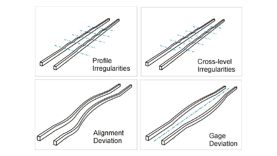
Key Track Geometry Parameters • Unevenness • Alignment • • Track irregularity in vertical plane Track irregularity in horizontal plane Gauge Variation in distance between two rails from standard distance of 1676 mm Twist Change in difference of level of two rails at specified distance
Track Parameters Unevenness, Alignment & Gauge
Track Parameters Gauge and Cross-level
Track Parameters Twist
Concept of Twist - Table B 3 A 2 1 Base X 4
Y A X I S X AXIS Z A X IS X AXIS Z Y A X I S
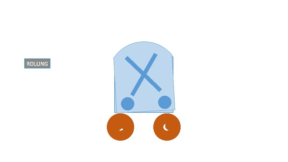
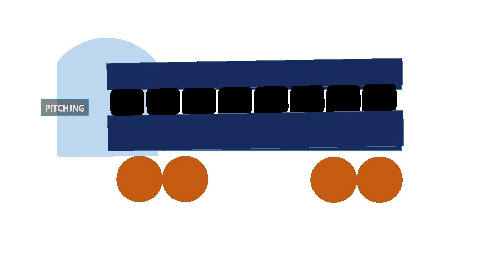
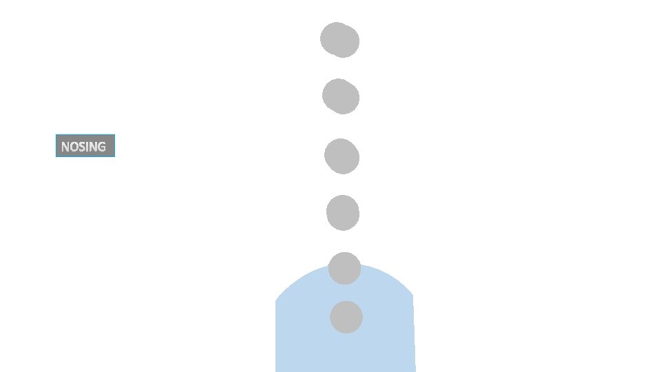
Nomenclature of Movements SN Movement Nomenclature Caused by A) Translational along X axis Shuttling Loose shunting B) Translational along Y axis Lurching Alignment defect including gauge variations. C) Translatonal along Z axis Bouncing Unevenness of rail top D) Rotational about X axis Rolling Cross level/ unevenness E) Rotational about Y axis Pitching Unevenness F) Rotational about Z axis Nosing Alignment defect Hunting- Combined Effect of Rolling and Nosing
X AXIS
Y A X I S
Z A X IS Z A
Objective of Track Measurement • To judge the track Performance • To identify the deviations or the defects • To compare the existing track standard/desired track parameters with • To monitor the rate of deterioration for special attention • To give timely input and prolong the life of the asset • To assess the quality of track maintenance inputs the
System of Measurement • Manual and Mechanized measurements • Manual Inspection • Push Trolley / Foot Inspections • Foot Plate and Brake Van Inspections • Manual Measurements • Measurement of Track parameters i. e. Unevenness, Alignment, Twist by measuring Cross Level, Gauge • Assessment of Lateral or Vertical Jerks
Limitations of Manual Measurement • • • Subjective - Depends upon Human Response Track parameters in Floating Condition only Time Consuming- Slow and Tiring No Continuous record of Track Geometry Not amenable to detailed analysis Inappropriate for Modern Track Structure and Mechanized Maintenance
Mechanised Measurement For objective assessment of track quality the following mechanized means are being used on Indian Railways. Ø Track Recording Cars (TRC) – TMM directorate of RDSO – Engineering Department Ø Oscillograph Cars – Mechanical Directorate of RDSO Ø Oscillation Monitoring System (OMS) – Divisions or Zonal Headquarters
Advantage of Mechanised Measurement • Objective assessment • Measurement in Loaded Condition • Systematic recording and analysis of data • Fast and convenient • Continuous record of track parameters • Less Human Intervention
Mechanized method of Measurements • Peak Based ØIt helps in identifying isolated localized defects ØFor Isolated attentions • Standard Deviation (SD) Based ØIt helps in identifying bad stretch ØIt is useful in deciding machine maintenance
SD- SAMPLE Station 1 2 3 4 5 6 7 8 9 10 11 12 13 14 15 16 17 18 19 20 G 0 5 3 -3 0 3 -2 0 0 -3 0 3 -3 1 3 -3 0 3 2 0 Average(μ) 0. 45 ∑(x−μ)^2 σ=√{∑(x−μ)^2 /N} (x−μ)^2 0. 20 20. 70 6. 50 11. 90 0. 20 6. 50 6. 00 0. 20 11. 90 0. 20 6. 50 11. 90 0. 30 6. 50 11. 90 0. 20 6. 50 2. 40 0. 20 G 15 5 3 -3 0 3 -2 0 -15 -3 0 3 -3 1 3 -3 0 3 2 0 (x−μ)^2 211. 70 20. 70 6. 50 11. 90 0. 20 6. 50 6. 00 0. 20 238. 70 11. 90 0. 20 6. 50 11. 90 0. 30 6. 50 11. 90 0. 20 6. 50 2. 40 0. 20 0. 45 110. 9 338. 2 2. 35 4. 11 24
Significance of Standard Deviation (σ) 99. 7% 95. 0 % 68. 2% σ= 2. 35 4. 70 2σ = 4. 70 3σ = 7. 05 0. 45 One σ away from the mean in either direction on the horizontal axis (red area on the above graph) accounts for about 68. 2 percent of the data Two σ away from the mean (red and green areas) account for 95 percent of the data Three σ (red, green blue areas) for on about percent the data The bell curve mayand be steep or flat account depending the 99. 7 spread of theofdata; Steep- Less value of SD Flat - More value of SD
Standard Deviation BASED and Peak Based Assessment • SD based Measurement takes into account magnitude of each and every data of vehicle ride while Peak based Measurement indicates no. of peaks exceeding a limit without giving an idea of magnitude of various peaks • Peak based Measurement facilitates isolated attention but deployment of machine over long stretches can not be decided. • More value of SD for any parameter indicates more variation and less uniform track profile. • Less value of SD for any parameter indicates less variation and more uniform track profile. • Uniform track profile results in better riding quality
Track Tolerances- How many? Tolerance s under Loaded Condition Tolerance s under Floating Condition • • New Track Tolerance (NTL) Planned Maintenance (PML) Need Based Maintenance (NBML) Urgent Maintenance (UML) • New Track • Existing track • Tolerance for Realignment of Curve • Slowdown Tolerance for Worksites/ Yard lines etc Tolerances For Machine Maintenance • Tamping Tolerance 27
Track tolerances Classification • New track tolerances (NTL) • Maintenance tolerances (ML) • Index or planning for maintenance tolerances (PML) • Need based maintenance tolerance (NBML) • Urgent Maintenance tolerances(UML) • Slow down tolerance • Safety tolerances
New Tr. Tolerance Maint. Tolera nce TRACK QUALITY Deterioration PML Tolerance NBML Tolerance Maintenance Inputs UML/Slow Down Tolerance Safety Tolerance TIME in Years
Change in Chord Lengths Present Chords S. N. Parameter Short Chord Long Chord 1 Unevenness 3. 6 m 9. 6 m 2 Alignment 7. 2 m 9. 6 m 3 Twist 3. 6 m 4. 8 m New Chords Approved by Board SN Parameter Short Chord / Base Long Chord/ Base 1 2 3 Unevenness Alignment Twist 9. 0 (UN-1) 9. 0 (AL-1) 3. 0 (TW-1) 18. 0(UN-2) 15. 0(AL-2) 15. 0 (TW-2)
New Track Tolerance • Highest level of track geometry that can be achieved on a new or relayed track with new material. • Best in terms of track quality. • Useful for controlling quality of track renewal, track relaying. • Should be practically achievable. • Nicely laid track results in lesser maintenance inputs & longer life of track assets besides resulting in savings in fuel consumption.
Track Tolerances for New Track under Load Condition (To be measured three months after speed is raised to normal) (i) SD Based for UN and AL SN Parameter Speed upto 100 Kmph Speed above 100 Kmph and upto 160 kmph 1 UN-1 2. 0 mm 1. 4 mm 2. UN-2 - 1. 9 mm 3. AL-1 1. 4 mm 1. 1 mm 4. AL-2 - 1. 3 mm (i) Peak Based for UN and AL SN Parameter Speed upto 100 Kmph Speed above 100 Kmph and upto 160 kmph 1. UN-1 6 mm 4 mm 2. UN-2 - 6 mm 3. AL-1 4 mm 3 mm 4. AL-2 - 4 mm
For measurements recorded in floating conditions: Gauge for new track: • For new track and through renewal of track, the following tolerances would be applicable • For Straight including curves of radius upto 350 m and more -5 mm to +3 mm • For curves of radius less than 350 m • Upto +10 mm
Sl. Other parameters for new track: Parameter Description of Measurement Value 1 Gauge Sleeper to sleeper variation 2 mm 2 Expansion gap Over average gap worked out by recording 20 successive gaps ± 2 mm Low joints not permitted High joints not more than ± 2 mm Square-ness of joints on straight ± 10 mm 3 Joints 4 Spacing of sleepers With respect to theoretical spacing ± 20 mm 5 6 Cross level To be recorded on every 4 th sleeper On straight on 10 m Chord Variation over theoretical versines: ± 3 mm ± 2 mm 7 (On 20 m Chord). Alignment 5 mm Variation over theoretical versines: (On 20 m Chord). 8 9 On curves of Radius more than 600 m On curves of Radius less than 600 m Longitudinal level Variation with reference to approved longitudinal sections. 10 mm 50 mm
Maintenance Tolerances. • Next best tolerances after new track tolerances. • Standards to which the track should be brought after maintenance cycle. • Lower than new track tolerances & gap between them increases with passage of time due wearing out of track components. • Theoretically depends on age of track structure, cumm GMT carried, method of maintenance. • Level of track quality attainable after each maintenance cycle goes on reducing due to wear & tear of track components with time
Maintenance Tolerance (Para 3. 1. 4, table 3. 1 of IRTMM) Acceptance criteria for Tamping of track As per Track machine manual Parameter <10 peaks Any peak Alignment ± 4 mm ± 6 mm X-Level ± 6 mm -Unevenness ± 6 mm ± 10 mm Note- (i)At least 4 stretches of 25 sleepers per km of tamped track should be recorded (ii) The versine and SE of curves for at least 10 stations should be recorded
Planned Maintenance Limit (PML) • These tolerances provide a guidance to plan through maintenance of track in a complete block section. These Limits, if exceeded, require that track geometry condition be analyzed and considered for planned maintenance operations. • PML are only for Unevenness and Alignment and are • Based on Standard Deviation (SD) values, as these parameters affect Ride quality. • Peak based limits are not stipulated
Need Based Maintenance Limit (NBML) • These limits are applying timely correction before the defects size grows to the level of Urgent Maintenance Limit (UML); requiring traffic slow down. Allowable time for attention to defects exceeding the NBML would depend upon the magnitude of the defects and various factors affecting track geometry deterioration such as sectional speed, axle load, traffic volume etc. • The Need Based Maintenance Limits (NBML) are based on Standard Deviation and Peak Values for Unevenness and Alignment. • For Gauge and Twist, these limits are based on Peak Values.
Urgent Maintenance Limits (UML) • These limits are so specified that upon their exceedences, the permitted speed should be reduced; which can be restored only after attending the track. • These are laid in terms of acceleration limits on comfort consideration and • peak values for Gauge and Twist.
Planned Maintenance Limit (PML) • Based on SD values only (no peak limits) • Of Alignment & Unevenness (which affects the Ride Quality) • SD values, if exceeded, Analyze track geometry condition , and • Consider for planned maintenance • Guidance to plan • Through maintenance of track in a complete block section • By track machines only.
Planned Maintenance Limit (PML) SD value for Param eter Speed upto 100 km/h Speed above 100 km/h and upto 110 km/h Speed above 110 km/h and upto 130 km/h Speed above 130 km/h and upto 160 km/h UN-1 5. 0 mm 3. 8 mm 3. 3 mm 2. 9 mm UN-2 - 5. 4 mm 5. 1 mm 4. 4 mm AL-1 3. 3 mm 2. 5 mm 1. 9 mm AL-2 - 4. 1 mm 3. 5 mm 2. 5 mm (9. 0 m) (18. 0 m) (9. 0 m) (15. 0 m)
Need Based Maintenance Limit (NBML) • Based on SD values and peak values • Of Alignment & Unevenness (which affects the Ride Quality) • For applying timely correction Before defect size grows to the level of UML • UML requires traffic to slow down • Allowable time for attention depends on • Magnitude of defect; and • Various other factors affecting track geometry • Sectional speed, axle load, traffic volume etc.
Need Based Maintenance Limit (NBML) Parameter UN-1 (9. 0 m) UN-2 (18. 0 m) AL-1 (9. 0 m) AL-2 (15. 0 m) Speed upto 100 km/h SD Value (mm) Peak value (mm) 6. 8 20 - - 4. 9 15 - -
Need Based Maintenance Limit (NBML) Parameter UN-1 (9. 0 m) UN-2 (18. 0 m) AL-1 (9. 0 m) AL-2 (15. 0 m) Speed above 100 km/h and upto 110 km/h SD Value (mm) Peak value (mm) 5. 5 17 7. 5 23 3. 9 12 6. 7 20
Need Based Maintenance Limit (NBML) Parameter UN-1 (9. 0 m) UN-2 (18. 0 m) AL-1 (9. 0 m) AL-2 (15. 0 m) Speed above 110 km/h and upto 130 km/h SD Value (mm) Peak value (mm) 4. 9 15 7. 4 22 3. 6 11 5. 3 16
Need Based Maintenance Limit (NBML) Parameter UN-1 (9. 0 m) UN-2 (18. 0 m) AL-1 (9. 0 m) AL-2 (15. 0 m) Speed above 130 km/h and upto 160 km/h SD Value (mm) Peak value (mm) 4. 4 13 6. 6 20 3. 6 11 4. 9 15
Need Based Maintenance Limit (NBML) • The limits for alignment are variation from average versine for curves. • For maintenance/realignment of curve • Para 421 remains applicable
Need Based Maintenance Limit (NBML) • Gauge • On straight • On curve with • Radius 440 m or more • Radius less than 440 m – 6 mm to +6 mm – 6 mm to +15 mm upto +20 mm Note- Uniform gauge over a long stretch is desirable.
Need Based Maintenance Limit (NBML) • Twist • On straight and curved track (other than on Transitions) • Generally within 2 mm/m; and • Upto 3. 5 mm/m at isolated locations • On transitions of curves • Local defects should not exceed 1 mm/m; and • Upto 2. 1 mm/m at isolated locations Isolated locations – shall not exceed 10 per km Chord/Base for twist = 3. 5 m
PML/NBML/UML Tolerances Speed upto 100 Kmph S. NO. Parameter PML SD 1. 0 NBML PEAK SD UML PEAK (mm) PEAK (Accn. ) Vertical and Lateral Acceleration 0. 30 g Unevenness 1. 1 UN-1 5. 0 6. 8 20 3. 3 4. 9 15 1. 2 UN-2 2. 0 Alignment 2. 1 AL 1 2. 2 AL 2 3. 0 Twist 3. 1 TW 1 5 mm/M 7 mm/M
PML/NBML/UML Tolerances Speed upto 100 Kmph (Contd…. ) S. NO. Parameter PML SD 3. 1 3. 2 NBML PEAK SD UML PEAK (mm) PEAK (Accn. ) A Straight -8 to +10 -10 to +12 B Curve-R > 440 -5 to +14 -7 to +17 C Curve-R < 440 -5 to +18 -7 to +20 A Straight -10 to +12 -12 to +15 B Curve-R > 440 -7 to +17 -11 to +20 C Curve-R < 440 -6 to +22 -8 to +25 Mean Gauge over 200 M section over Nominal gauge Isolated defects –Nominal Track Gauge to Peak Value
PML/NBML/UML Tolerances Speed > 100 < = 110 Kmph S. NO. Parameter PML NBML SD 1. 0 2. 0 3. 0 PEAK UML SD PEAK (mm) PEAK (Accn. ) Vertical and Lateral Acceleration 0. 30 g Unevenness 1. 1 UN-1 3. 8 5. 5 17 1. 2 UN-2 5. 4 7. 5 23 2. 1 AL 1 2. 5 3. 9 12 2. 2 AL 2 4. 1 6. 7 20 Alignment Twist 3. 1 TW 1 4 mm/M 7 mm/M
PML/NBML/UML Tolerances Speed > 100 < = 110 Kmph (Contd…. ) S. NO. Parameter PML SD 3. 1 3. 2 NBML PEAK SD UML PEAK (mm) PEAK (Accn. ) A Straight -8 to +10 -10 to +12 B Curve-R > 440 -5 to +14 -7 to +17 C Curve-R < 440 -5 to +18 -7 to +20 A Straight -10 to +12 -12 to +15 B Curve-R > 440 -7 to +17 -11 to +20 C Curve-R < 440 -6 to +22 -8 to +25 Mean Gauge over 200 M section over Nominal gauge Isolated defects –Nominal Track Gauge to Peak Value
PML/NBML/UML Tolerances Speed > 110 < = 130 Kmph S. NO. Parameter PML NBML SD 1. 0 2. 0 3. 0 PEAK UML SD PEAK (mm) PEAK (Accn. ) Vertical and Lateral Acceleration 0. 25 g Unevenness 1. 1 UN-1 3. 3 4. 9 15 1. 2 UN-2 5. 1 7. 4 22 2. 1 AL 1 2. 5 3. 6 11 2. 2 AL 2 3. 5 5. 3 16 Alignment Twist 3. 1 TW 1 4 mm/M 6 mm/M
PML/NBML/UML Tolerances Speed > 110 < = 130 Kmph (Contd…. ) S. NO. Parameter PML SD 3. 1 3. 2 NBML PEAK SD UML PEAK (mm) PEAK (Accn. ) A Straight -8 to +10 -10 to +12 B Curve-R > 440 -5 to +14 -7 to +17 C Curve-R < 440 -5 to +18 -7 to +20 A Straight -10 to +12 -12 to +15 B Curve-R > 440 -7 to +17 -11 to +20 C Curve-R < 440 -6 to +22 -8 to +25 Mean Gauge over 200 M section over Nominal gauge Isolated defects –Nominal Track Gauge to Peak Value
PML/NBML/UML Tolerances Speed > 130 < = 160 Kmph S. NO. Parameter PML NBML SD 1. 0 2. 0 3. 0 PEAK UML SD PEAK (mm) PEAK (Accn. ) Vertical and Lateral Acceleration 0. 20 g Unevenness 1. 1 UN-1 2. 9 4. 4 13 1. 2 UN-2 4. 4 6. 6 20 2. 1 AL 1 1. 9 3. 6 11 2. 2 AL 2 2. 5 4. 9 15 Alignment Twist 3. 1 TW 1 3. 5 mm/M
PML/NBML/UML Tolerances Speed > 130 < = 160 Kmph (Contd…. ) S. NO. Parameter PML SD 3. 1 3. 2 NBML PEAK SD UML PEAK (mm) PEAK (Accn. ) A Straight -6 to +10 -8 to +12 B Curve-R > 440 -5 to +13 -7 to +15 C Curve-R < 440 -5 to +18 -7 to +20 A Straight -8 to +12 -10 to +15 B Curve-R > 440 -6 to +16 -9 to +20 C Curve-R < 440 -6 to +22 -8 to +25 Mean Gauge over 200 M section over Nominal gauge Isolated defects –Nominal Track Gauge to Peak Value
• In case of acceleration peak exceeding the UML for a speed band, the permitted speed should be reduced to a lower speed level keeping in view the aforesaid criteria and be restored only after attending the track.
Realignment criteria for Curves: • The running over a curve depends not only on the difference between the actual versine and the designed versine but also on the station to station variation of the actual versine values, which determines the rate of change of lateral acceleration, on which depends the riding comfort.
Sl. Speed on curve 1 Below 140 km/h and upto 110 km/h 2 Below 110 km/h and upto 50 km/h 3 Below 50 km/h Limits of Station to Station Variation of Versine (mm) 10 mm (15 mm for speed of 110 km/h); or 20% of average versine on circular portion, whichever is more. 20 mm; or 20% of average versine on circular portion, whichever is more. 40 mm; or 20% of average versine on circular portion, whichever is more.
Note: • In case exceedences of the above Limit is observed during inspection, local adjustment may be resorted to in cases where the variation of versine between adjacent stations is only at a few locations, at the earliest possible. If more than 20% stations are having versine variations above the limits prescribed, complete realignment of curve should be planned within a month.
Track Parameters in floating conditions: • During Maintenance: • Gauge: • While it is desirable to maintain correct gauge, variation in gauge may be there due to age and condition of the rail, sleepers, and fastenings. The limits of gauge as per measurement in floating condition, for the guidance of the Engineering officials regarding condition of track from passenger comfort perspective, shall be as given below, provided that generally a uniform gauge can be maintained over long lengths
Broad Gauge (Reference nominal gauge of 1676 mm) a)On straight Track -6 mm to +6 mm a) On curves with radius 440 m or -6 mm to +15 mm more a) On curves with radius less than 440 Up to + 20 mm m In case of exceedences of these limits, the results of last TRC/OMS shall be analyzed for planning suitable maintenance action.
Twist: • It is desirable to maintain the track geometry for a comfortable ride at Sectional Speed. The limits of twists as per measurement in floating condition, for guidance of the Engineering officials regarding condition of track from passenger comfort perspective, shall be as under (to be calculated on a base of 3. 0 m) • On straight and curve track, other than transition – 3. 5 mm/m • On transition of curve- 2. 1 mm/m (Local defects above Designed value) • In case of exceedences of above limits, the results of last TRC/OMS shall be analyzed for planning suitable maintenance action.
Track parameters for low speeds: (Slow Down Tol) • For guidance of field officials following track parameters are stipulated, in floating conditions, for maintenance of tracks where speeds are low such as worksite, yard line, etc. : Speed (in km/h) Upto 45 Upto 30 Upto 15 Peak value of UN Peak value of twist (on 3. 6 m chord) (on 3. 0 m chord) in mm 22 24 33 18 21 25 Permissible gauge range -10 to +27 mm -12 to +27 mm
Safety tolerance • The stability of train against derailment depends upon on several factors such as : • track geometry, vehicle characteristics and state of their maintenance & • speed of the particular vehicle at relevant point of time etc. • Rail wheel interaction is, thus, a complex phenomenon and, therefore, safety tolerance for track alone cannot be prescribed in Isolation. Accordingly, safety tolerances for maintenance of track have not been prescribed on Indian Railways. Each derailment case, therefore, other factors considered relevant, to arrive at the cause. The provisions and tolerances mentioned hereinbefore and elsewhere in this Manual are with a view to maintain track geometry for good riding comfort.
Thanks