What is Seismic Retrofitting Seismic retrofitting is the


 in a building can “hang")


")


 Stiffness Irregularity – Soft Storey: A soft storey is one")


 of MR frame buildings without infills (solid walls), Ta = 0.")


 Epoxy Resins: Epoxy resins")
 Epoxy Mortar: The epoxy mortar is made using epoxy resin and sand. It")


 Detail B 4 (a)Section A - A")


- Slides: 134
What is Seismic Retrofitting Seismic retrofitting is the modification of existing structures to make them more resistant to seismic activity, ground motion or soil failure due to earthquakes. There are several techniques which have come forward nowadays by which an existing structures can be modified and make it less prone to earthquakes. There is no such technique to make the structure fully earthquake proof but seismic performance can be greatly enhanced through proper initial design or subsequent modifications.
Objectives: 1. Public safety To protect human life, ensuring that the structure will not collapse. 2. Structure survivability The structure remaining safe may require extensive repair but not replacement 3. Structure functionality Primary structure undamaged and the structure is undiminished in utility for its primary application 4. Structure unaffected A high level of retrofit is preferred for historic structure of cultural significance
Need for Seismic Retrofitting of Buildings Ø Buildings not designed according to the codes of practice Ø Buildings designed to meet the modern seismic codes, but deficiencies exist in the design and/or construction Ø Essential buildings must be strengthened like hospitals, historic monuments and architectural buildings Ø Buildings that are expanded, renovated or rebuilt Ø Deterioration of strength of the buildings Ø Not considering the safety of buildings while construction Common seismic retrofitting techniques 1. Base Isolators 2. Supplementary dampers 3. Tuned mass dampers 4. Slosh tank 5. Active control system
Base isolators: Base isolation is one of the most powerful means of protecting a structure against earthquake forces. It is meant to enable a building to survive a potentially devastating seismic impact through proper initial design or subsequent modifications. Base isolation system consists of 1. Isolation units 2. Isolation components Isolation units consists of shear or sliding units. They are intended to provide the decoupling effect to a building. Isolation components are the connections between isolation units and their parts having no decoupling effect of their own.
Working of base isolators: Base isolators is a technique developed to prevent or minimize damage to building during an earthquake. When a building is built away (isolated) from the ground, resting on flexible bearings or pads known as base isolators, it will move little or not at all during an earthquake. They consists of basic components – a lead plug, rubber and steel, which are generally placed in layers.
Rubber – The rubber provides flexibility. At the end of an earthquake, the rubber bearing will slowly bring the building back to its original position. Lead – lead has plastic property. During an earthquake, the kinetic energy of the earthquake is absorbed into heat energy as the lead is deformed. Steel – If layers of steel are used with rubber, the bearing can move in the horizontal direction but is stiff in the vertical direction.
Structures with modern isolation base
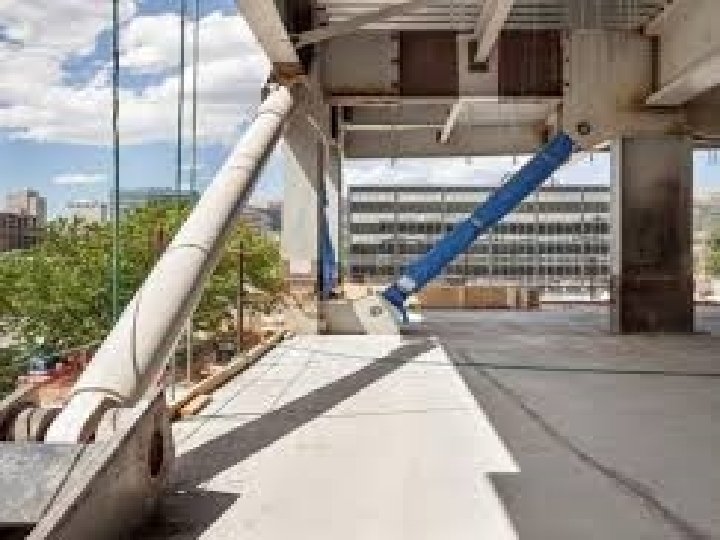
Supplementary Dampers: A supplementary Damping System is essentially an energy dissipation system that is incorporated into the design of a structure to absorb vibration energy, thereby reducing motion. Supplementary damping is the most efficient and cost effective way to achieve energy dissipation in building. This would inadvertently mean decreasing the energy dissipation demand on the structural components i. e. beams/columns/slabs thereby increasing the survivability of the building structure.
Dampers are mechanical devices that look somewhat like huge shock absorbers and their function is to absorb and dissipate the energy supplied by the ground movement during an earthquake so that the building remains unhamered. Whenever the building is in motion during an earthquake tremor or excessive winds, dampers help in restricting the building from swaying excessively and thereby preventing structural damage. The energy absorbed by dampers gets converted into heat which is then dissipated harmlessly into the atmosphere. Dampers thus work to absorb earthquake shocks ensuring that the structural members remain unharmed.
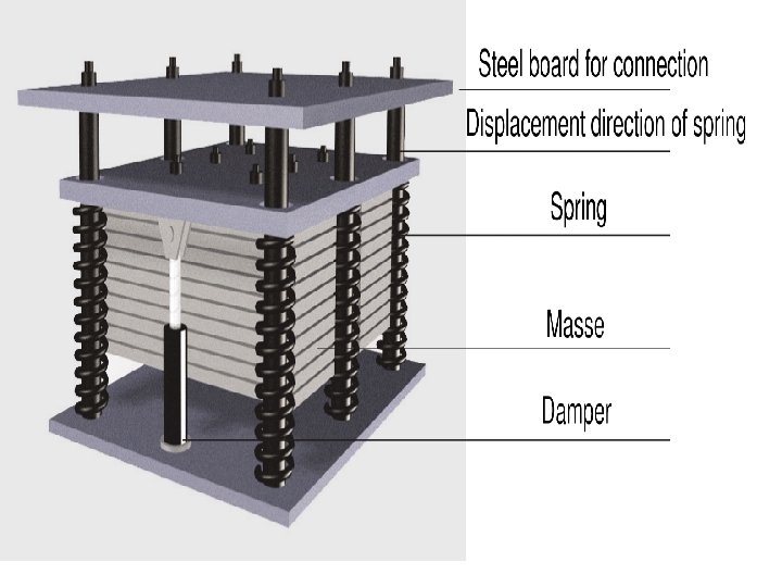
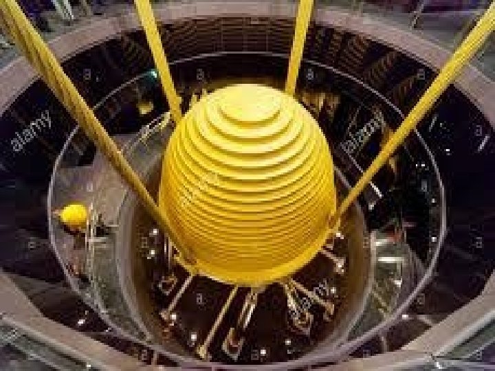
Tuned Mass Dampers: is a device mounted in structure to reduce the amplitude of mechanical vibrations. Their application can prevent discomfort, damage or outright structural failure. They are frequently used in power transmission, automobiles and buildings. Tuned mass dampers stabilize against violent motion caused by harmonic vibration. It reduces the vibration of a system with a comparatively lightweight component so that the worst case vibrations are less intense. Practical systems are tuned to either move the main mode away from a troubling excitation frequency or to add damping to a resonance that is difficult to damp directly
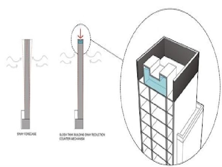
Slosh Tank: In fluid dynamics, slosh refers to the movement of liquid inside another object undergoing motion. To reduce structure motion due to external loadings in high rise building, slosh tank is one of the inventions that can be installed in different locations and levels into a structure in order to increase damping and decrease vibrations. It can either be installed on the top floor of a structure or in some certain floors or even at each floor of a building.
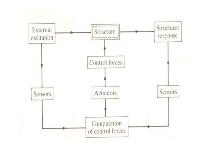
Active control System: Active control systems are force delivery devices integrated with real-time processing evaluators/controllers and sensors within the structure. They act simultaneously with the hazardous excitation to provide enhance structural behaviour for improved service and safety. An active structural control system consists of: a) Sensors located around the structure to measure either external excitations, or structural response variables, or both. b) Devices to process the measured information and to compute necessary control force needed based on a given control algorithm. c) Actuators, usually powered by external sources, to produce the required forces.
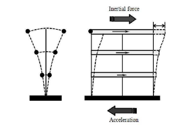
HOW BUILDINGS RESPOND TO EARTHQUAKES The earthquake as well as wind load acting on the buildings are termed as ‘lateral loads’ since their effect is felt mainly in the horizontal direction. This is in contrast to the weights of the building, which act vertically down due to gravity. Forces due to earthquake, called seismic forces, are induced in a building because of the heavy masses present at various floor levels. Such forces are called inertial forces, is calculated by the products of the masses and their respective accelerations. If there is no mass, there is no inertial force. Accelerations generated by the seismic waves in the ground get transmitted through the vibrating structure to the masses at various levels, thereby generating the so-called horizontal seismic forces. The building behaves like a vertical cantilever, and swings horizontally almost like an inverted pendulum, with masses at higher levels swinging more. Hence, the generated seismic forces are higher at the higher floor levels. Because of the cantilever action of the building (fixed to the ground and free at the top), the forces accumulate from top to bottom. The total horizontal force acting on the ground storey columns is a sum of the forces (seismic loads) acting at all the levels above. This is termed as the base shear and it leads to highest stresses in the lowermost columns.
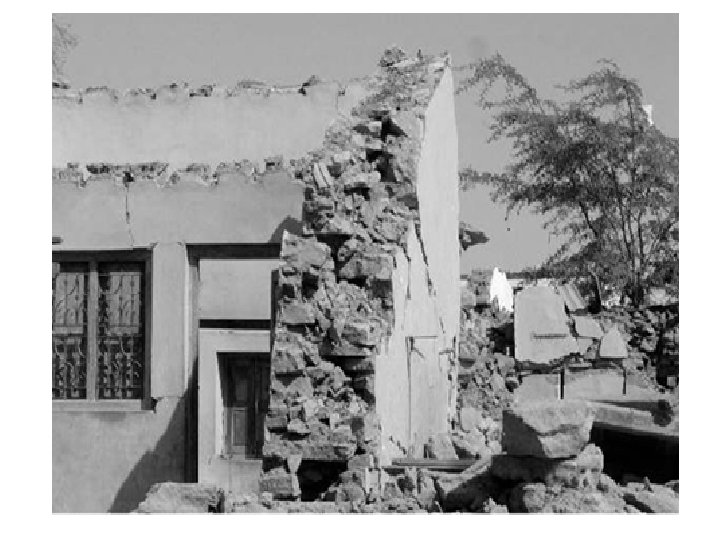
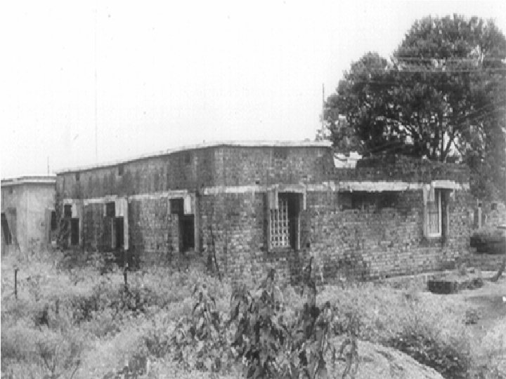
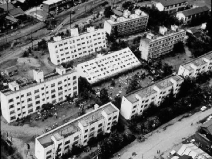
Heavier buildings attract larger seismic forces. On the other hand, lighter buildings are affected less. This was an important lesson learned from the great Assam earthquake of 1897 (magnitude M 8. 1), which destroyed almost all buildings (up to 3 storeys) built in British India. Following this disaster, constructions were limited to single and double storeyed “Assam type” dwellings with light roofing as ideal earthquakeresistant construction in North-East India, which falls under the highest seismic zone (zone V) in the country. Over the years, these basic lessons have been forgotten, and numerous high-rise buildings have mushroomed, especially in recent times in the urban centres of the country. Many of these buildings are seismically deficient. Figure shows an old building in Guwahati, originally 4 storeyed, to which three additional storeys were added recently �an example of a potential man- made disaster, waiting to happen, in a highly congested area. To prevent such disasters, local building authorities must strictly ensure that all new constructions should comply with design standards. Existing buildings that are highly unsafe must be declared unfit for occupation (and, if located in congested areas, must be demolished), unless they are retrofitted appropriately.
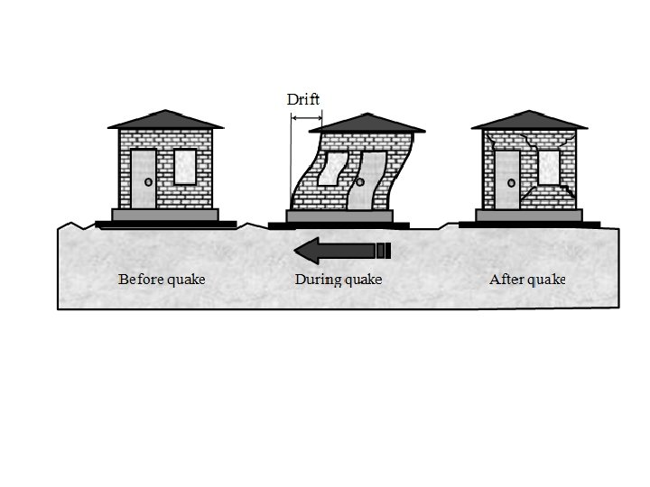
1. Effect of Stiffness Buildings are expected to behave elastically under service loads. Elasticity is that property by which a body or a structure, displaced by a load, regains its original shape upon unloading. It is by virtue of this property, that buildings that are pushed horizontally by wind or mild earthquake loads, return to the original vertical configuration after the wind or the tremor has passed. How much the building deflects under a given load is measured by a property called stiffness, which may be defined as “the force required to cause unit deflection”. The stiffness required to resist lateral forces is termed as lateral stiffness. The stiffer the building, the less it will deflect (‘drift’)
Should our buildings be relatively stiff or flexible? Certainly, it is desirable for the building to behave elastically under lateral loads, including forces under low earthquake levels that are likely to occur occasionally during the life of the building. But, it would be highly uneconomical to design ordinary buildings to behave elastically under high level earthquakes, which are rarely expected to occur during the design lifetime of the building. Because of the limitation of resources, the design standards allow us to take some risk of damage in the event of a rare severe earthquake. What we need to ensure is that the building, although likely to be severely damaged in the event of the rare earthquake, does not collapse, so that lives are not lost. How do structural engineers achieve this? They allow the building to behave inelastically (that is, the building does not regain its original shape after the earthquake) at such high load levels and thus dissipate energy. The building’s original stiffness gets degraded, and it becomes flexible.
Of course, there must be adequate stiffness in buildings. This can be achieved by providing adequate lateral load resisting systems (such as masonry walls with bands in small buildings, frames, braces or shear walls in large buildings). Otherwise, they will get severely damaged and may even collapse under low level earthquakes. In the case of exceptionally important buildings (such as nuclear reactors), it is even desirable to have sufficient stiffness to ensure elastic behaviour even under rare earthquakes. They must survive at all cost, and that too without damage. The mass and lateral stiffness of the building contribute to another important structural property, called the natural period of vibration. It is the time taken by the building to undergo a cycle of to-and-fro movement (like a pendulum). Buildings with high stiffness and low mass have low time period, whereas buildings with low stiffness and high mass have high natural period. The value of this natural period also governs the magnitude of seismic force that the building will attract. This is similar to the effect of resonance in a vibrating system. The conventional buildings of a few storeys, common in urban areas, have low natural period and hence attract higher seismic forces as a fraction of their weight.
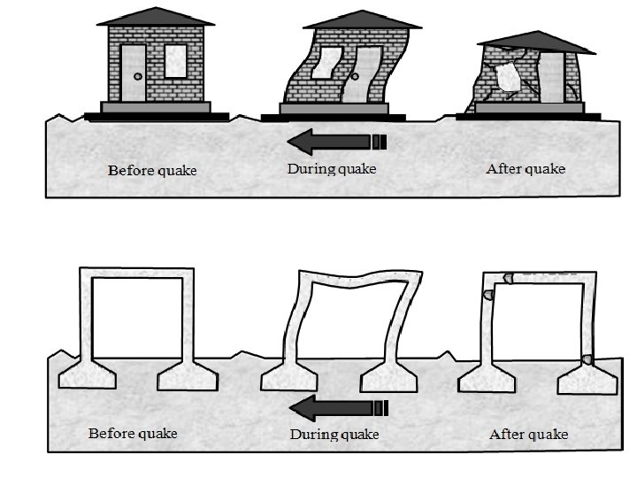
2. Effect of Ductility The ability of a structure to deform with damage, without breaking suddenly (without warning), is termed as ductility. With ductility, a building can continue to resist seismic forces without collapsing. There is a story of a proud tree teasing a blade of grass for not being able to stand erect in the wind. But, when a very severe storm came, it was the tree which fell down and the blade of grass survived. This is because the blade of grass was able to undergo very large deformation without breaking down, unlike the big tree which snapped suddenly at its base, when its strength was exceeded. In a similar way, buildings too can exhibit either ductile or brittle (non-ductile) behaviour, depending on the structural material, design and detailing. Generally, conventional masonry buildings exhibit brittle behaviour, when provided with earthquake resistant features. On the other hand, well-designed buildings made with reinforced concrete or structural steel can exhibit ductile behaviour.
Materials like brick, stone and plain concrete are relatively brittle. When bricks or stones are used in masonry wall construction without adequate bond, they can fall apart suddenly, even if the walls are relatively thick. This indeed is how the failure of many buildings occurred during the Latur earthquake. Many such buildings have weak mud mortar and absence of bond stones. Ordinary buildings are commonly classified as either load bearing or framed structures. Most low-rise buildings are load bearing buildings made of masonry walls, which resist both gravity (vertical) loads and lateral loads due to wind and earthquake. As the building height increases, and in high seismic zones, lateral loads tend to govern the design. In such cases, it is structurally efficient and economical to adopt framed buildings. In such buildings, it is the framework (skeleton) of the building, comprising beams, columns and footings, made usually of reinforced concrete, which mainly resist both vertical and lateral loads. In high-rise buildings, reinforced concrete shear walls are often introduced to enhance the lateral load resisting capacity.
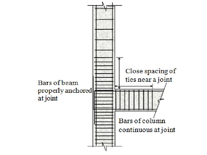
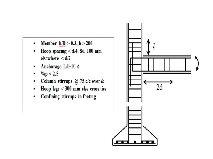
Unlike brick and stone, materials like steel and reinforced concrete (if properly designed and detailed) possess considerable ductility. Ductility is required at locations of very high stress, such as the beam-column joint. The horizontal bars in the beam should be anchored well in the joint and the vertical ties spaced closely near the joint. The vertical bars and the closely spaced horizontal ties in the column should be continuous throughout the joint. These important details are often overlooked in reinforced concrete construction, whereby the desired ductility is not achieved.
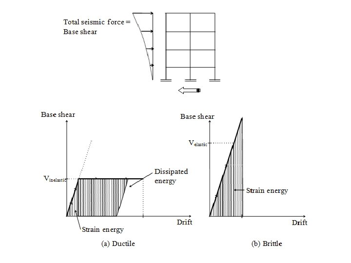
If the structural components (walls, beams, columns etc. ) in a building can “hang on” through ductile behaviour, without breaking down during the brief period of the major earthquake, the building will not collapse, even though it may get damaged. Such ductile buildings attract lesser load with increasing deformation (since stiffness gets reduced) than the buildings which remain stiff (like the tree in our story). Also, a significant amount of the input energy due to the earthquake in the building gets dissipated through the yielding (deformation without increase in stress) of the ductile materials. Otherwise, the entire input energy needs to be stored as elastic strain energy. The strain energy and the dissipated energy are shown by the shaded areas in the base shear versus drift graphs. However, as the drift is generally much less in the latter type of buildings, the total seismic force to be resisted by such a building is very high to handle the same input energy. This is not practical for ordinary buildings, because it calls for very large member sizes and will be prohibitively expensive. If the desired ductility can be provided in the building, the design seismic force Vinelastic can be much lower (up to 20%) than the corresponding force in an elastic building Velastic.
3. Effect of Strength and Integrity Every structural component has strength, which is the magnitude of the maximum internal force (such as axial force or bending moment) it can resist under a certain type of loading. When this strength is exceeded by the applied load, the material fails (or collapses). The strength depends not only on the type of material, but also on other factors, such as the size of the cross-section. However, the thicker wall will attract higher earthquake force. As mentioned earlier, the load attracted by a structural component during an earthquake depends on the mass and lateral stiffness of the building. If the building is not designed to “yield”, and behave in a ductile manner, it will be required to resist higher load during an earthquake to prevent a sudden failure. A structural component should be designed to have a strength that is not less than the maximum internal force, associated with the overall seismic load on the building, and the associated ductility.
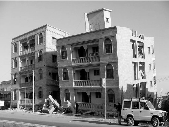
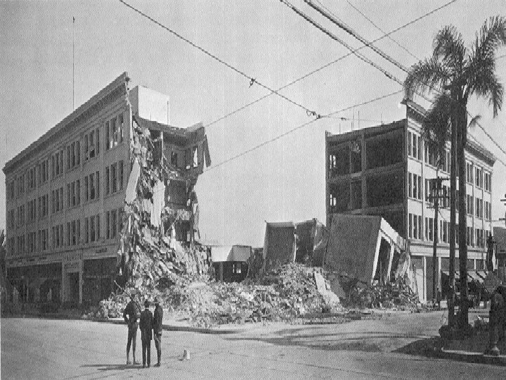
If the strength is not adequate, the building component will fail. The failure of the vertical components in a building (such as load bearing walls, columns or footings) is more critical than that of the horizontal components (such as beams and slabs), because the former type of failure is likely to trigger a possible collapse of the entire building. The failure of a beam may cause only a local distress; but the failure of a ground storey column or a footing can trigger overall building (global) collapse. In the recent Gujarat earthquake, many multistoreyed buildings collapsed because of the failure of the columns in the ground storey.
Thus, an important principle adopted in the seismic resistant design of framed buildings is this: Soil must be stronger than foundations; foundations must be stronger than columns; columns must be stronger than beams. To ensure that forces are safely transmitted from beams to columns, from columns to foundations, and from foundation to soil, the connections at the beam-column joints, column- foundation joints and foundation-soil interface should have the required strength (and ductility). This requirement is part of ensuring the integrity of the building. Retaining the stiffness in the building is the other aspect of integrity. Consider, for example, a single room, bounded by four masonry walls and covered by a roof slab. If the connections between the walls and between the slab and the walls are not effective, the building has limited strength and stiffness to resist seismic forces, and can collapse even under a minor earthquake shaking. Indeed, this is precisely what happened to a large number of dwelling units during the Latur earthquake.
In a masonry building, if reinforced concrete bands are provided in walls at plinth, lintel and roof levels and the wall-to-wall connections provide good bond, the walls will act together like a box. This will enable the building to resist even a major earthquake effectively. The more the number of lateral load-resisting systems in a building, the less is the potential for global collapse. This is because when one of them fails, the loads get redistributed, and other systems take an increasing share of the load. This potential for having multiple load paths in a building is called redundancy and it makes the building as a whole stronger.
4. Effect of Layout and Configuration Providing earthquake resistance to buildings is primarily the responsibility of civil engineers. But architects also have a major role to play. Some architectural features, relating to overall size and shape, are unfavorable and invite potential seismic disaster. It is desirable that the client also knows something of these features, if the building is located in a high seismic zone. Prevention is always better than cure. In such situations, safety is preferable to fancy looks. Otherwise, structural design has to be done carefully and competently. In general, if the basic architectural features favoring good seismic resistance are adopted, the cost of making the building earthquake proof is less.
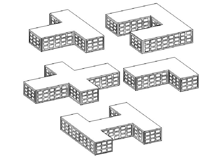
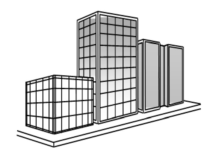
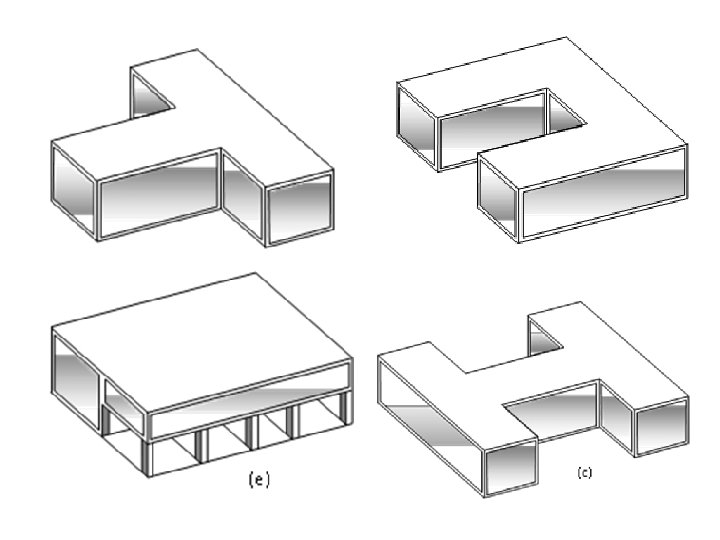
The, building should have a simple geometrical shape in plan, such as rectangular or circular. All rectangular shapes are not uniformly good. If the building is too long (in one direction) or too large in plan, it is likely to be damaged during earthquakes. Buildings with large cut-outs in the walls, floors and roofs are undesirable, as this affects their integrity. Similarly, buildings which have ‘L’, ‘U’, ‘V’, ‘Y’ or ‘H’ shapes in plan are also undesirable, inviting severe stresses at the interior corners called re-entrant corners. Each wing of the building tends to vibrate separately in the event of an earthquake, causing serious problems at the common core region, leading to potential collapse.
Buildings with asymmetry in plan are bound to twist under an earthquake, inviting further damaging effects. A general rule of thumb is to make the building as simple, solid and symmetric in plan as possible. If complex geometries are absolutely required, then it is desirable to break up the building plan into separate simple rectangular segments with proper separation joints, so that they behave as individual units under an earthquake.
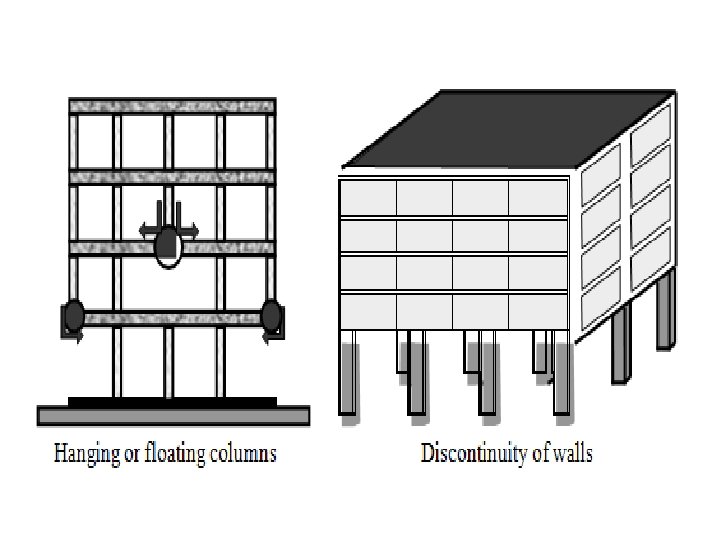
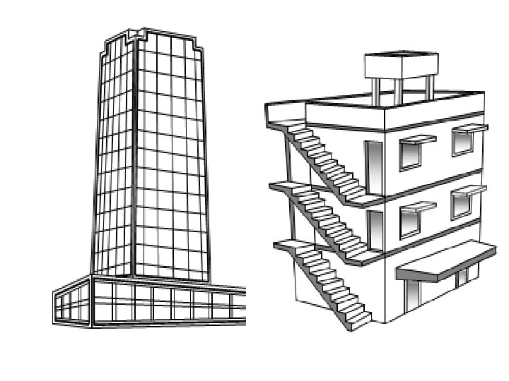
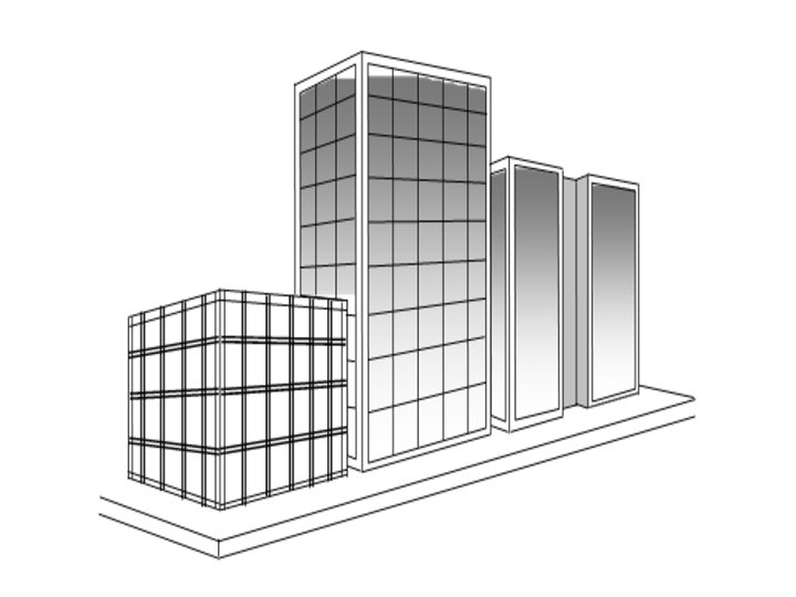
Buildings should not only be simple in plan but also in elevation. The walls and columns should continue uninterrupted from top to bottom, to ensure transmission of forces to the supporting ground through the shortest and simplest path. If there is any discontinuity in this path of load transmission, there is a danger of potential damage to the building in the event of an earthquake. Hence, hanging or floating columns (columns which begin in an upper storey from a beam) and discontinuity of walls in the ground or other storey (open ground storey) should be avoided.
In the 2001 Gujarat earthquake, many buildings with open ground storey collapsed and the parked cars were flattened. This is because the sudden change in stiffness at the ground storey induces extreme high stresses in the ground storey columns, which were not accounted for in the design. Buildings with vertical setbacks (either plaza type buildings, or with cantilever projection at the top) or many overhanging projections perform poorly in terms of seismic resistance. In fact, all overhanging projections including balconies should be avoided, as these are the first elements to collapse in the event of an earthquake.
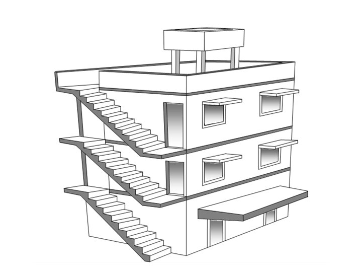
Special attention should be given to the planning of the staircases, as these vital escape routes are at times the first ones to attract damage in a major earthquake. To ensure their survival, the slabs should ideally be supported on inclined beams (stringer beams) which connect integrally with the main frame in the building. This provision is usually neglected by architects.
Two buildings or two structurally isolated sections of a single building should not be too close to each other, as there is a danger of possible collision against each other. This effect is called pounding and is usually not considered in design. The effect is more severe for tall buildings. It is recommended that a calculated gap subject to a minimum value be maintained between the buildings to avoid pounding. Otherwise, there can be serious damage to both the buildings or building sections, even if they are designed adequately individually.
5. Effect of Soil The accelerations that occur in the rock layer of the crust during an earthquake get transmitted to the building through the soil over the rock layer. When the soil is relatively soft, the accelerations tend to get magnified, resulting in the structure attracting higher seismic loads. This must be taken into account during structural design. Knowledge of the soil strata is also essential for designing the foundations of the building. Buildings located in loose granular soils (sands), in the presence of subsoil water, have another serious and potential danger that can occur during an earthquake. The soil can behave like quicksand through a phenomenon called liquefaction. This happens because of a sudden increase in pore water pressure on account of seismic shear waves, causing the water-sand mixture to flow upwards and practically convert the soil behaviour to that of a liquid. Buildings located in such soils may sink or go afloat, and tilt significantly and collapse.
Introduction to Seismic Analysis and Design The subject of earthquake engineering has received a major emphasis in recent years, and specially in the wake of the 2001 earthquake in Gujarat. It is now well realized that earthquake loads need to be considered explicitly in the design of structures. • Earthquakes cause the ground to shake violently, thereby triggering landslides, creating tsunamis and floods, and causing the ground to heave and crack, resulting in large-scale destruction to life and property. • The study of why and where of earthquakes comes under geology. • The study of the characteristics of the earthquake ground motion and its effects on engineered structures are the subjects of earthquake engineering. • The effect of earthquakes on structures and the design of structures to withstand earthquakes with low damage is the subject of earthquake resistant structural design. • Local site effects such as ground subsidence, liquefaction and site amplification are studied under geotechnical earthquake engineering.
Earthquake load differs from other loads in many respects, which makes it more difficult to design for it. Some of the characteristics of earthquake loading are as follows • Earthquake loading is uncertain with respect to its amplitude, duration, and frequency content. • Earthquake loading is predominantly lateral and can cause severe damage unless special provisions are made to resist them. • Earthquake loading is cyclic and induces reversal of stresses. • Earthquake loading is dynamic and produces different degree of response in different structures. These characteristics make seismic analysis and design extremely difficult and time- consuming and so simplified procedures are often used in practice.
EARTHQUAKE RESISTANT DESIGN AND CONSTRUCTION The key for good seismic design is simplicity in plan and elevation. Structures, which have more than one axis of symmetry and have uniform distribution of strength and stiffness are said to be regular structures. Structures, which do not satisfy one or more of the above requirements, are said to be irregular. Irregular structures exhibit special problems during earthquakes and should be avoided as far as possible. Masonry and infill (non-structural) walls should be reinforced by vertical and horizontal reinforcing bands to avoid their failure under a severe earthquake. It should be noted that wood is not ductile and needs to be reinforced with steel to withstand severe earthquakes. Also other nonstructural elements should be carefully designed so that they do not cause injury to people. Reinforced Concrete elements should requires extra stirrups at potential hinging locations and extra anchorage lengths. It should be remembered that steel structures perform better than RC structures and should be adopted for all important buildings such as schools, multi-storied buildings and hospitals. Pre-cast elements should be tied securely so that they don’t get dislodged during the earthquake. Projecting elements such as porches, sun-shades, water tanks, balconies and parapet walls cause serious injuries to people and so should be designed to withstand earthquake loading without developing instability.
Some of the common irregularities and their effects along with possible retrofitting strategies are described below. 1. Asymmetric plan/Asymmetric structural action Building plan with one or no axis of symmetry or building with asymmetric structural action – Earthquake induced inertia force acts at centre of mass, CM. – Building resistance acts at the centre of stiffness, CS. – Resulting couple twist the building. Affect all types of buildings such as masonry, reinforced concrete with or without shear walls and steel buildings. Retrofitting strategy: reduce asymmetry to bring CM near CS.
2. Reentrant corners Building plans with re-entrant corners Re-entrant corners tend to open and close during vibration. Opening leads to cracking and closing leads to crushing at reentrant corners. Retrofitting strategy: Cut plan into separate wings
3. Open to sky, Ducts /atriums Building with large open to sky ducts and/or staircases placed between floor areas (Figure 2. 5). Cutting of floor diaphragms for light, ventilation, staircases and lifts disturbs force transfer between floor areas. Affect multi-storeyed building with reinforced concrete slabs over floor areas. Retrofitting strategy: Install horizontal steel bracings in ducts and separate the staircase.
4. Staggered column buildings Buildings with columns not in line and/or oriented in different directions. Buildings with 230 mm columns (Figure 2. 6) Inadequate frame action to resist seismic loads in either direction. 230 mm columns are too weak and flexible for buildings over 2 -storeys. Affect reinforced concrete framed buildings Retrofitting strategy: Provide reinforced concrete shear walls over entire height.
5. Stilt floor buildings Buildings with full or partial area of ground floor having stilts to facilitate parking or other activity, like shops with rolling shutters (Figure 2. 7). Absence of walls reduces stiffness of ground storey making it “soft” The soft storey gets damaged during earthquake and the building tends to sit due to crushing of columns. Affect reinforced concrete buildings with strong masonry walls in upper floors. Retrofitting strategy: Stiffen the ground storey by RC shear walls or steel bracings.
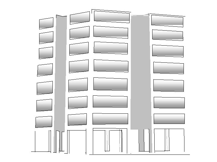
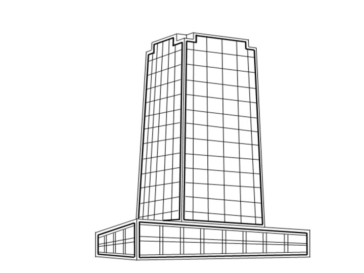
6. Plaza type buildings Buildings with large built-up areas in lower storeys and a tower rising above as in hotels shopping mall cum office buildings (Figure 2. 8). – Sudden reduction in stiffness causes damage at the base of tower. – Affect all types of buildings including modern reinforced concrete buildings and older/historic masonry buildings. Retrofitting strategies: Provide steel bracing and/or reduce tower height.
7. Clustered buildings Buildings close to one another as in city business areas and sometimes having common walls (Figure 2. 9). Building hit or pound each other during earthquakes due to insufficient space for vibration. Affect all types of buildings. Retrofitting strategy: Increasing gap by demolishing or provide bridge bearings in between.
8. Non-ductile buildings Reinforced buildings not detailed as per IS: 13920 (Figure 2. 10) and masonry buildings without reinforcement bands. Buildings disintegrate due to inadequate integral action. Affect reinforced concrete and masonry buildings. Retrofitting strategy: Provide extra frames and tie all elements together.
9. Buildings with projecting elements Buildings with large projections like canopies, balconies, sunshades, parapets, and water tanks in the roofs (Figure 2. 11). Horizontal projecting elements generally develop stability problems and tend to overturn. Vertically projecting elements experience amplified excitations and so develop stability problems. Affect all types of buildings except light weight sheetings. Retrofitting strategy: Reduce projections or reduce their weight. Alternatively they may be braced or anchored to main elements.
Seismic Design Philosophy Severe earthquakes have an extremely low probability of occurrence during the life of a structure. If a structure has to resist such earthquakes elastically, it would require an expensive lateral load resisting system, which is unwarranted. On the other hand, if the structure loses its aesthetics or functionality quite often due to minor tremors and needs repairs, it will be a very unfavorable design. The usual strategy is: In addition to strength requirements at the ultimate load, structures are also designed to have adequate stiffness in the lateral direction under service loads. This is usually ensured, by limiting the relative displacement between successive floors, known as the storey drift. For buildings, a maximum allowable storey drift of 0. 004 times the storey height is normally used under moderate earthquakes.
Analysis and Design for Earthquake Loads Structures are usually designed for gravity loads and checked for earthquake loading. In conformity with the design philosophy, this check consists of two steps - the first ensures elastic response under moderate earthquakes and the second ensures that collapse is not allowed under a severe earthquake. Due to the uncertainties associated in predicting the inelastic response, the second check may be dispensed with, by providing adequate ductility and energy dissipation capacity. The important factors, which influence earthquake resistant design are, the geographical location of the structure, the site soil and foundation condition, the importance of the structure, the dynamic characteristics of the structure such as the natural periods and the properties of the structure such as strength, stiffness, ductility, and energy dissipation capacity. These factors are considered directly or indirectly in all the methods of analysis. The response spectrum method has the advantage that, it can account for irregularities as well as higher mode contributions and gives more accurate results. Therefore, this is the most widely used method in seismic analysis.
General Design Requirements The IS 1893 code gives guidelines to classify buildings as regular or irregular based on simple calculations. If a building is regular, a simplified method of analysis can be adopted. The types of irregularities defined in the code are
Plan Irregularities 1. Torsion Irregularity: To be considered when floor diaphragms are rigid in their own plan in relation to the vertical structural elements that resist the lateral forces. Torsional irregularity to be considered to exist when the maximum storey drift, computed with design eccentricity, at one end of the structures transverse to an axis is more than 1. 2 times the average of the storey drifts at the two ends of the structure. 2. Re-entrant Corners: Plan configurations of a structure and its lateral force resisting system contain re-entrant corners, where both projections of the structure beyond the re- entrant corner are greater than 15 percent of its plan dimension in the given direction. 3. Diaphragm Discontinuity: Diaphragms with abrupt discontinuities or variations in stiffness, including those having cut-out or open areas greater than 50 percent of the gross enclosed diaphragm area, or changes in effective diaphragm stiffness of more than 50 percent from one storey to the next. 4. Out-of-plane offsets: Discontinuities in a lateral force resistance path, such as out-of- plane offsets of vertical elements. 5. Non-parallel systems: The vertical elements resisting the lateral force are not parallel to or symmetric about the major orthogonal axes or the lateral force resisting element.
Vertical Irregularities 1. a) Stiffness Irregularity – Soft Storey: A soft storey is one in which the lateral stiffness is less than 70 percent of that in the storey above or less than 80 percent of the average lateral stiffness of the three storeys above b) Stiffness Irregularity – Extreme Soft Storey: A extreme soft storey is one in which the lateral stiffness is less than 60 percent of that in the storey above or less than 70 percent of the average stiffness of the three storeys above. For example, buildings on STILTS will fall under this category. 2. Mass Irregularity: Mass irregularity shall be considered to exist where the seismic weight of any storey is more than 200 percent of that of its adjacent storeys. The irregularity need not be considered in case of roofs.
3. Vertical Geometric Irregularity: Vertical geometric irregularity shall be considered to exist where the horizontal dimension of the lateral force resisting system in any storey is more than 150 percent of that in its adjacent storey. 4. In-Plane Discontinuity in Vertical Elements Resisting Lateral Force: A in-plane offset of the lateral force resisting elements greater than the length of those elements. 5. Discontinuity in Capacity – Weak Storey: A weak storey is one in which the storey lateral strength is less than 80 percent of that in the storey above. The storey lateral strength is the total strength of all seismic force resisting elements sharing the storey shear in the considered direction.
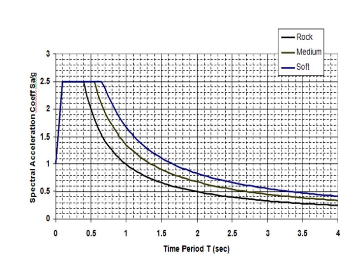
Calculation of Earthquake Loads The horizontal seismic coefficient Ah takes into account the location of the structure by means of a zone factor Z, the importance of the structure by means of a factor I and the ductility by means of a factor R. It also considers the flexibility of the structure-foundation system by means of an acceleration ratio Sa/g , which is a function of the natural time period T. This last ratio is given in the form of a graph known as the response spectrum. The horizontal seismic coefficient Ah is given by Ah = Z I S a / 2 R g where, Z = Zone factor corresponding to the seismic zone obtained from a map I = Importance factor R = Response reduction factor. Zone factor Z Seismic zone II IV V Seismic intensity Low Moderate Severe Very severe Z 0. 10 0. 16 0. 24 0. 36
For important service and community buildings, such as hospitals, schools; monumental structures; emergency buildings like telephone exchange, television stations, radio stations, railway stations, fire station buildings; large community halls like cinemas, assembly halls and subway stations, power stations, the importance factor may be taken as 1. 5 but for most buildings it may be taken as 1. 0. The response reduction factor R is also specified for various buildings depending on the type of detailing adopted. For example, if a building is detailed as per ductile detailing provisions given in IS 13920, then the R factor is 5, else it is 3. The natural time period T is very important and should be calculated correctly. For single storey structures, it may be taken as T = 2π√(k/m) where k is the lateral (horizontal) stiffness of the supporting structure and m is the mass of the roof usually taken as the sum of the roof dead load plus 50% of the live load divided by the acceleration due to gravity.
Fundamental natural period(sec) of MR frame buildings without infills (solid walls), Ta = 0. 075 h 0. 75 for RC buildings Ta = 0. 085 h 0. 75 for steel buildings where, h= height of building in m. And, for frames with infills, Ta = 0. 09 h/√d where d= base dimension of the building at the plinth level in m
Finally, the acceleration ratio Sa/g can be obtained from the graph corresponding to Ta and the soil type in Figure. In this figure, medium soil corresponds to stiff clay or sand soft soil corresponds to loose clay and loamy soils. The base shear is then given by Vb=Ah W The base shear calculated above is then distributed along the height of the building using the formula, Qi = VB Wi hi *2/ ∑ Wi hi *2 Qi is the lateral force at the top of floor i, Wi is the total of dead and appropriate amount of live load at the top of floor i, hi is the height measured from the base of the building to the top of floor i, n is the number of storeys.
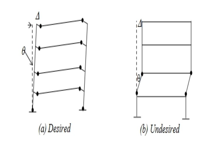
Capacity Design and Detailing With reference to framed structures, it has been found that some collapse mechanisms ensure larger energy dissipation capacities compared to some other collapse mechanisms. The technique of ensuring a preferred collapse mechanism by suitably adjusting the capacities of the members is called Capacity Design. In practice, due to the difficulties associated with inelastic analysis and design, no attempt is made to calculate the actual capacities in relation to seismic demand it is only ensured that the members and joints of the structure have adequate ductility and energy dissipation capacities and the structure as a whole will fail in a preferred collapse mechanism.
The type of collapse mechanism developed largely dictates the overall ductility and energy dissipation capacity of the frame and so capacity design is invariably carried out. In capacity design, the type of collapse mechanism required is pre-decided and attempts are made to make sure that no other mechanism develops. In multistory frames, the strong column-weak beam mechanism is preferred since this mechanism requires the formation of many plastic hinges and also the plastic rotation capacity required at the hinges is less (Figure 2. 13). The term plastic rotation capacity is used in place of ductility when talking about the moment-rotation curve instead of the usual force-deformation curve.
The characteristics of earthquake loads were described. The dual strategy of ensuring elastic response under moderate earthquakes and preventing collapse under a severe earthquake was explained. The properties of the structure, particularly ductility and hysteretic energy dissipation capacity, which aid in resisting earthquake loads, were pointed out. The architectural considerations, which can simplify the design process and assure good seismic performance, were described. The elastic and inelastic response prediction methods such as seismic coefficient, response spectrum and time-history analysis were explained. The background concepts on which most codal provisions are based were also explained. Guidelines to improve the seismic behaviour of steel structures were given at the material, member and structure levels. In particular, the hysteretic behaviour and collapse modes of bracing members and flexural members with various crosssections were described in detail. The behaviour of lateral load resisting systems such as bracings and moment resistant frames was described. The concept of capacity design, which aims at maximising the energy dissipation capacity of moment resisting frames by choosing an appropriate collapse mechanism, was explained. Finally, an overview of special devices and systems, which can be used to control the response and thus reduce the design forces for members, was given.
Retrofit of Non-Engineered Buildings Non-engineered buildings are those, which are not formally designed, but built using traditional techniques. They are made of mud/brick/stone/concrete walls, wooden/bamboo posts and thatch/tile/wooden/concrete roofs. Recent earthquakes and cyclones have revealed their vulnerability to lateral loads. Hence, it is necessary to retrofit the building to mitigate the disaster possible in such events. Today we will discuss seismic retrofit for the buildings, information on the preferred seismic resistance features of non-engineered buildings, the features aim to enhance the integrity of the buildings. The horizontal bands and vertical reinforcement at key locations, proper size and location of the openings and features in typical buildings are to be highlighted.
• We will also discuss available repair materials and techniques, the advanced repair materials such as shotcrete, epoxy resin, epoxy mortar, quick setting cement mortar, micro-concrete, fibre-reinforced concrete, ferro- cement and a few others are to be covered to provide some ready information. • The strengthening techniques are broadly grouped as member level and global techniques. Under the member level techniques, the strengthening of roofs, upstairs floors, walls and pillars are to be discussed. Under the global techniques, the introduction of joints, walls, pilasters, buttresses and braces, improvements of the frame and splint and bandage strengthening techniques, several connection details are to be covered.
INTRODUCTION Many building are constructed in the traditional manner without formal design by qualified engineers or architects. The material include field stone, brick, concrete blocks, rammed earth, wood posts, thatch, tiles, concrete etc. if blocks are used to make the walls, they are attached together with mud, lime or cement mortar. Sometimes, combination of mortars is also used. Such buildings are built using combination of load bearing walls, piers in masonry, columns in reinforced concrete, steel or wood posts. The safety of these buildings against earthquakes is of great concern, as huge losses of lives have occurred in such buildings during past earthquakes. During the survey after the earthquakes, it has been observed that the main reason for the damage to these buildings are the use of non-engineered construction methods without adequate earthquake resistant features, and the poor quality of workmanship. Hence, Bureau of Indian Standards published the codes of practice for earthquake safety of non-engineered and semi-engineered buildings.
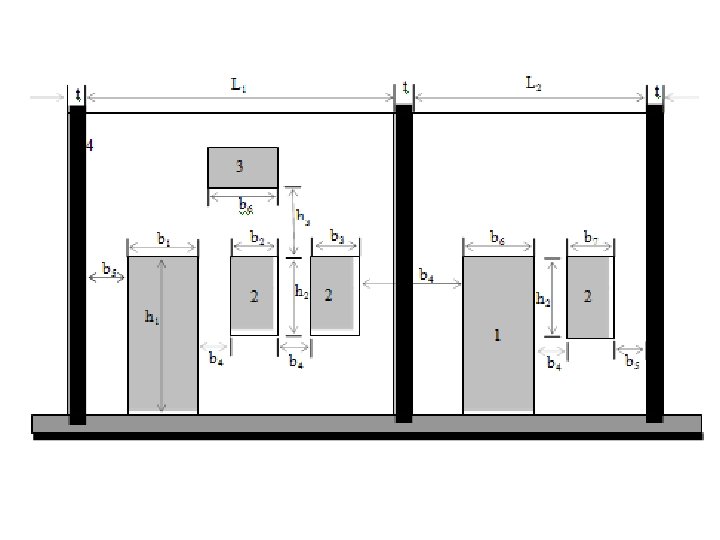
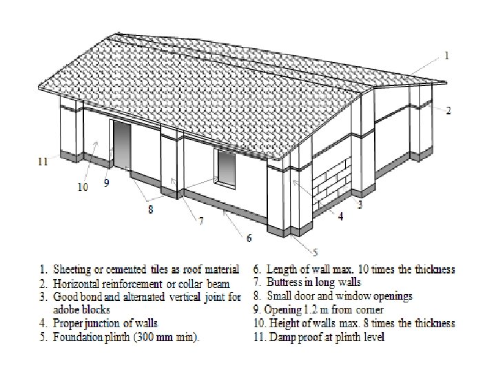
SEISMIC RESISTANT FEATURES Based on the material, non-engineered building can be broadly classified for Earthquake Resistant Non-engineered Construction. • Buildings in brick and other masonry units • Stone buildings • Wooden buildings • Earthen buildings • Non-engineered reinforced concrete buildings The different parts of building should be tied together s o that the building acts as one unit under seismic forces. The essential features for resisting seismic forces are § The building should be tied to its foundation § Horizontal bands of reinforcement are to be provided at the plinth level, sill level, lintel level and roof level. Vertical reinforcing bars are to be provided at the corners of the building, junctions of walls and around the openings in walls. § There should be horizontal bracing at the roof level for sloping roofs. § The opening should be small and centrally located.
The roof band is required when the roof is sloping and roof is made of flexible material, such as tiles on purlins and rafters. The roof band is not necessary when roof is made of flat concrete slab. For better seismic resistance, opening should be located away from the inside of a corner by a certain distance. The width of the pier between two openings should not be less than a minimum value. The total length of openings should not exceed a certain percentage of the span of a wall. The features for seismic resistance as per IS 4326: 1993, IS 13827: 1993 and IS 13828: 1993 are shown in figure. The specific limits are available in the codes.
REPAIR MATERIALS: The interventions to enhance the seismic performance of a building can be broadly grouped under the categories of repair, rehabilitation and retrofit. The traditional materials used for repair are mud, lime, cement, sand, brick, stone and steel. Wood, bamboo posts are often used for supports and braces. Cement and lime is combined with sand water to prepare a mortar. Various types of cement with properties such as shrinkage compensation, low heat evolution and sulphate resistance are preferred for specific repair applications. Steel is used in the form of bolts, threaded rods, angles, channels and prestressing strands.
A brief summary of a few advanced materials are A) Epoxy Resins: Epoxy resins are used for Ø To bond plastic concrete to a hardened concrete surface Ø To bond two rigid materials Ø For patch work Ø For applying a coating over concrete surface to give colour, resistance to penetration of water and chemicals and resistance to abrasion. Epoxy resins are excellent binding agents. The low viscosity resins can be injected into small cracks. The higher viscosity resins are used as coating and for filling larger openings or holes.
B) Epoxy Mortar: The epoxy mortar is made using epoxy resin and sand. It has high compressive strength, high tensile strength and low modulus of elasticity. Epoxy resins can be used as a second binder in cement mortar. Here, the polymer particles join and form chain link reinforcement, increasing the tensile and flexural strengths of cement mortar. There is greater plasticity and reduction in shrinkage stress. C) Quick Setting Cement Mortars: These are the patented mortars generally having two components and are sold in a pre-packed state. D) Shotcrete: Shotcrete is a method in which compressed air forces mortar or concrete through a nozzle to be sprayed on a surface of building component such as wall, at a high velocity. The materials used in Shotcrete are generally same as those used for conventional concrete. The reinforcement provided is welded wire fabric or deformed bars tacked on the existing surface.
Micro-concrete: Based on hydraulic binders, these ready-made formulations are customized to produce concrete which is flowable and free of shrinkage. They are applied in complicated locations and in thin sections such as concrete jackets. Fibre-reinforced Concrete: Fibre-reinforced concrete has better tensile strength as compared to conventional concrete. They also have improved ductility (energy absorption capacity) and durability. They are being increasingly used for structural strengthening. Fibre-reinforced Polymers: The fibre-reinforced polymer (FRP) composites are made up of a polymer matrix and fibres. The fibres can be of glass, or carbon. They possess high strength to weight ratios, high fatigue strength, high wear resistance, vibration absorption capacity, dimensional stability, high thermal and chemical stability and corrosion resistance. They are manufactured in long lengths. FRP wraps can be used to strengthen structural members. Ferro-cement: Ferro-cement is constructed of cement mortar reinforced with closely spaced layers of small diameter wire mesh. The mesh may be made of steel or other suitable material. The mortar should be compatible with the opening size and weight of the mesh. The mortar may contain discontinuous fibres. The use of ferro-cement can be economical even for non-engineered buildings.
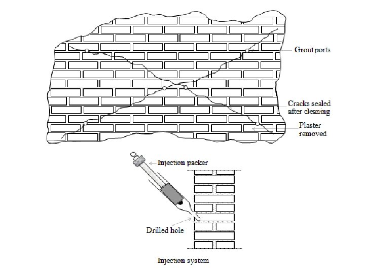
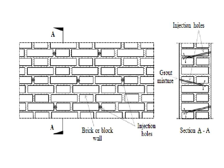
REPAIR TECHNIQUES The applicability of repair techniques varies depending on the problems to be addressed. The associated techniques are to be presented under specific problems. Small Cracks: Cracks reduce the strength of load bearing members especially when they are not reinforced, as in masonry or plain concrete. Hence, they should be marked carefully and the critical ones repaired. Cracks that are small in width (˂0. 75 mm) can be effectively repaired by pressure injection of epoxy. The surfaces are thoroughly cleaned of loose materials. Injection ports are placed along the length of the cracks on both sides, at intervals approximately equal to the thickness of the member. Low viscosity epoxy resin is injected into the ports sequentially, beginning at the port at the lowest level and moving upwards one by one. The resin is pushed through the packer till it is seen flowing from the other end or from a port higher than where it in injected. The port is closed at this junction and the packer is moved to the next higher port. Larger cracks will require larger packer spacing depending on thickness of the member. Vacuum injection has a typically fill level of 95 % and can fill cracks as small as 0. 025 mm. a similar technique can be applied to strengthen weak walls.
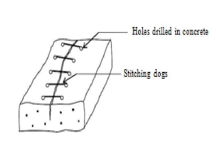
Large Cracks and Crushed Material: For cracks with width larger than 6 mm or in regions were brickwork or concrete is crushed, the following procedure is suitable. Loose material in the crack is removed any of the repair mortar mentioned is filled. If necessary, the crack is dressed to have a V groove. At wide cracks, fillers like flat stone chips can be used. To prevent widening of the cracks, they can be stitched. The stitching consists of drilling small holes of diameter 6 to 10 mm on both sides of the crack, cleaning the holes, filling up these with epoxy mortar and anchoring the legs of stitching dogs (U shaped steel bars of diameter 3 to 6 mm with short legs). The stitching dogs can have variable length and orientation. The spacing of the reinforcement should be reduced at the ends of the crack. Stitching will not close the crack, but it prevents further propagation and widening of the crack. The stitching will stiffen the area near the vicinity of the crack. Damaged Reinforcement: After an earthquake, the reinforcement in a reinforced concrete element can be severely damaged, showing signs of either buckling or elongation due to yielding. The element can be repaired by attaching new bars with the old bars by either lap or butt welding. Additional stirrups are added at the locations of damage and then covered with concrete to provide confinement of the existing concrete.
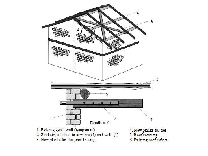
STRENGTHENING OF ROOFS The roof should effectively distribute the lateral load generated due to earthquake, to the walls. In other words, the roof should act as a horizontal diaphragm. There are varieties of roofs in non-engineered buildings. The most common types of roofs are considered. Timber Truss Roofs A timber roof truss usually supports tiles which are brittle and tend to get dislodged. The tiles can be replaced with galvanised iron corrugated sheets. A false ceiling of brittle material is hazardous. Ductile material like bamboo matting or light foam type material can be used to replace brittle false ceiling. Anchors of roof trusses to supporting walls should be improved and the roof truss thrust on the walls should be minimized or eliminated. This can be achieved by providing new bracing as shown
• Terrace Roofs • Where the roof consists of prefabricated units or channels, integration of individual units is a must. The units can be integrated by a cast-insitu reinforced concrete topping and a band. The technique is similar to that shown in fig. The detail can also be adopted for Madras terrace roof.
• Roofs of Light Weight Sheets • Although roofs made of asbestos or galvanised iron/aluminum sheets do not cause heavy damage to the building because of their light weight, there is damage in the roofs during earthquakes. This can be reduced by close spacing of the hold down bolts, which connect the sheets to the purlins.
• Thatched Roofs • Thatch made from leaves of palm and coconut trees is widely used as roofing material in rural areas. Thatched roof are blown off during cyclones, damaged during earthquakes and are also vulnerable to fire. The performance of the thatched roof can be significantly improved by holding it down using ropes in a diagonal fashion.
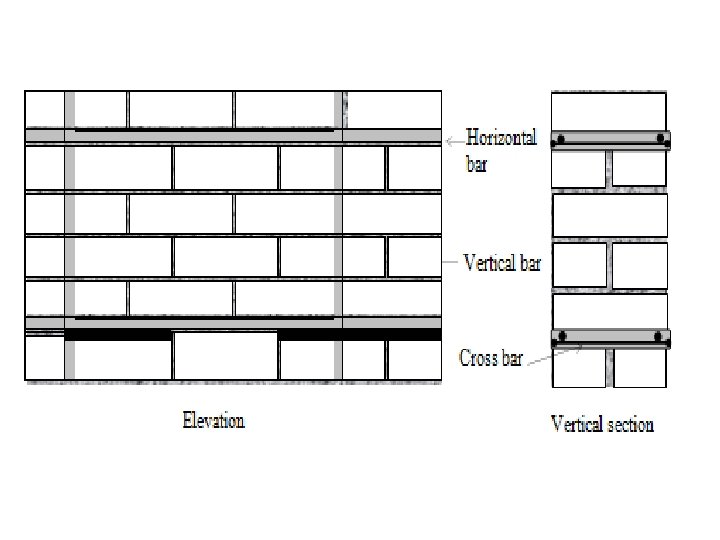
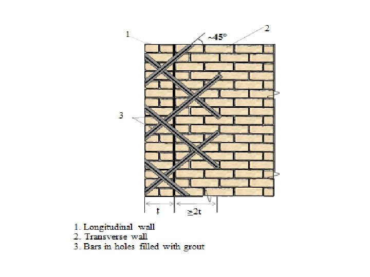
STRENGTHENING OF WALLS The walls support the roof and upstairs floor, as well as provide resistance to lateral load. The walls can be strengthened by the following methods. Grouting Containment reinforcement Use of Ferro-cement Use of fibre reinforced polymer Containment Reinforcement: In this method, first grooves are made in the mortar joints. Next, horizontal, vertical and cross bars are inserted in the grooves which are subsequently covered by mortar. Corners and T-junctions in perpendicular walls can be connected by effective stitching of the walls. In this method, first, holes are drilled in an inclined pattern. Next, steel bars are placed in the holes. Subsequently, grout is injected to form the bond between the bars and the wall, as well as to provide protection against corrosion of the bars. Generally, 8 to 10 mm diameter bars of grades Fe 415 are used for stitching. In multi-leaf walls, the inner filling can be strengthened by injection of grout. A collar band can be provided at the junction of two perpendicular walls at the lintel level to enhance the structural integrity. In many buildings, the partition walls are the first ones to collapse during an earthquake. To avoid failure, such a wall should be integrated by stitching with the two walls at its ends.
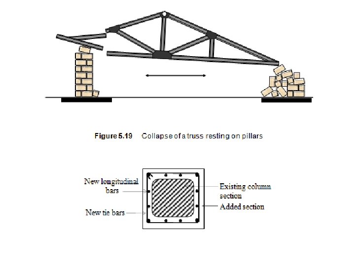
• STRENGTHENING OF PILLARS • In a barrack type of building, pillars made of bricks are placed along the corridor. These pillars support the roof trusses. In absence of any reinforcement, the pillars are weak under lateral forces, leading to failures. Such pillars can be strengthened by concrete jacketing as shown. The additional stirrups can be inserted from the top of the pillars after lifting the truss by a temporary support. Else, each stirrup has to be made of two pieces as shown under column jacketing. The trusses should be properly anchored to the pillars.
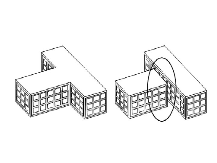
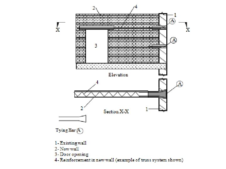
• TECHNIQUES FOR GLOBAL STRENGTHENING • Global strengthening aims to improve the lateral load resistance of the building as a whole. This will relieve overloaded members and ensure better seismic behaviour. • Introduction to Joints: • The buildings having large aspect ratio (length-tobreadth ratio) or projections in plan, behave badly during earthquakes. Such buildings can be separated into blocks with a crumple section in between them. New walls are inserted and tied with the existing walls to avoid long length of walls and to reduce the distance between centre of mass and centre of rigidity for each block.
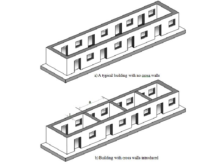
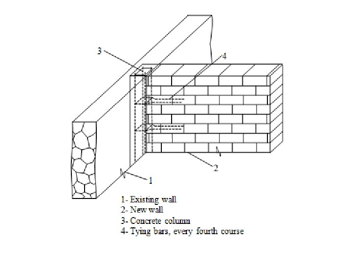
• Introduction of Walls: • Long walls are vulnerable to out-of-plan collapse. For a wall of thickness t and cross wall spacing a, the ratio a/t should not exceed 40. To ensure this cross walls can be added as indicated in figure. The spaces can be utilized appropriately without significantly altering the functionality of the building. This type of intervention is possible in long barrack type buildings used for schools, dormitories or other purpose. The junction between the new wall and the old wall will be a T -junction. The details of tying reinforcement are given in IS 13935: 1993.
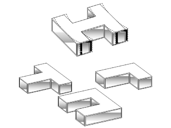
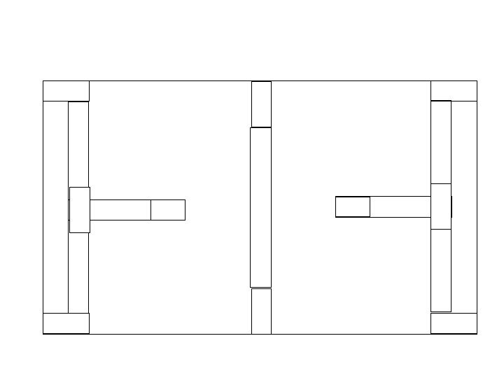
• Introduction of Pilasters or Buttresses: • In the case of longitudinal walls of the barrack type buildings, pilasters or buttress walls added externally will enhance lateral load resistance. The buttresses need to be integrated with the existing wall by key stones.
2 2 1 1 3 B (c) Detail B 4 (a)Section A - A 1 Existing wall 3 Key stones 2 Buttress or pilaster 4 Foundation
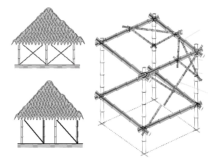
• Improvement of the Frame: • Most of the non-engineered constructions do not have adequate lateral load resistance. The rural hut made with bamboo posts is a typical example. Two modes of collapse of the frame is shown in figure. Figure shows how the introduction of braces in the periphery stabilizes the frame. Provision of doors can be accommodated by providing braces on either side as shown in the second sketch of the same figure. There can be cross braces or knee braces in the vertical planes of the walls or in the horizontal plane at the top of the walls, as shown.
» 1. Earthquake force 2. Failure of joints 3. Collapse frame Collapse modes of a typical hut
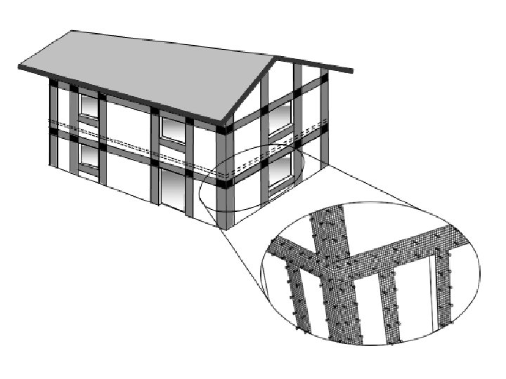
• Splint and Bandage Strengthening Technique • To economise in the retrofit cost while targeting to enhance the integrity of the building, Ferro-cement with galvanised welded steel wire mesh can be added on the exterior of the walls in the form of vertical splints adjacent to openings and horizontal bandages over the openings as shown. • The techniques covered in this discussion are intended to provide various options for retrofitting nonengineered buildings. However, given the wide variety of non-engineered buildings, differences in the detailing for each technique are expected to be based on the local condition and availability of materials, skills and funds. Hence, importance should always be placed on the detailing while designing the most appropriate repair and retrofit scheme for a building.