Design of Seismic Resistant Steel Building Structures 5

Design of Seismic. Resistant Steel Building Structures 5. Buckling Restrained Braced Frames Prepared by: Michael D. Engelhardt University of Texas at Austin with the support of the American Institute of Steel Construction. Version 1 - March 2007

Design of Seismic-Resistant Steel Building Structures 1 - Introduction and Basic Principles 2 - Moment Resisting Frames 3 - Concentrically Braced Frames 4 - Eccentrically Braced Frames 5 - Buckling-Restrained Braced Frames 6 - Special Plate Shear Walls
 • Description and Basic Behavior of Buckling. Restrained")
5 - Buckling-Restrained Braced Frames (BRBFs) • Description and Basic Behavior of Buckling. Restrained Braced Frames and Buckling-Restrained Braces • AISC Seismic Provisions for Buckling-Restrained Braced Frames
 • Description and Basic Behavior of Buckling. Restrained Braced Frames")
Buckling-Restrained Braced Frames (BRBFs) • Description and Basic Behavior of Buckling. Restrained Braced Frames and Buckling-Restrained Braces • AISC Seismic Provisions for Buckling-Restrained Braced Frames
 • Type of concentrically braced frame. • Beams, columns and")
Buckling-Restrained Braced Frames (BRBFs) • Type of concentrically braced frame. • Beams, columns and braces arranged to form a vertical truss. Resist lateral earthquake forces by truss action. • Special type of brace members used: Buckling. Restrained Braces (BRBs). BRBS yield both in tension and compression - no buckling !! • Develop ductility through inelastic action (cyclic tension and compression yielding) in BRBs. • System combines high stiffness with high ductility.

Buckling-Restrained Brace Buckling. Restrained Brace: Steel Core + Casing Steel Core

A A Buckling-Restrained Brace Casing Buckling. Restrained Brace: Steel Core + Casing Steel Core Steel jacket Mortar Debonding material Section A-A

Buckling-Restrained Brace P P Steel core resists entire axial force P Casing is debonded from steel core - casing does not resist axial force P - flexural stiffness of casing restrains buckling of core

Buckling-Restrained Brace Buckling. Restrained Brace: Steel Core + Casing Steel Core Yielding Segment Core projection and brace connection segment

Brace Behavior Under Cyclic Axial Loading P Conventional Brace: Py • yields in tension (ductile) PCR • buckles in compression (nonducile) • significantly different strength in tension and compression P
")
Brace Behavior Under Cyclic Axial Loading P Buckling-Restrained Brace: • yields in tension (ductile) Py PCR Py • yields in compression (ductile) • similar strength in tension and compression (slightly stronger in compression) P

Bracing Configurations for BRBFs Single Diagonal Inverted V- Bracing X- Bracing V- Bracing Two Story X-
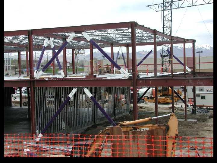
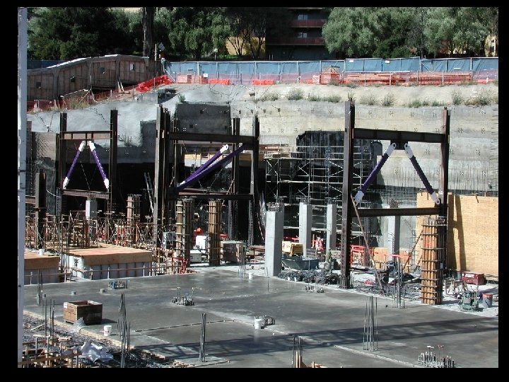
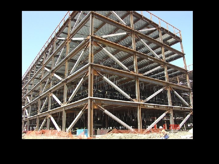
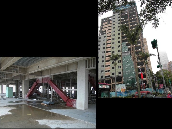

Inelastic Response of BRBFs under Earthquake Loading

Tension Brace: Yields Compression Brace: Yields Columns and beams: remain essentially elastic

Compression Brace: Yields Tension Brace: Yields Columns and beams: remain essentially elastic

Design of BRBFs - General Approach • Size BRB core for code specified forces (strength and stiffness) • Choose BRB design with performance verified by testing (Per Appendix T) • Design all other frame elements (beams, columns, brace connections, column bases) for maximum forces that can be generated by fully yielded and strain hardened BRBs
 • Description and Basic Behavior of Buckling. Restrained Braced Frames")
Buckling-Restrained Braced Frames (BRBFs) • Description and Basic Behavior of Buckling. Restrained Braced Frames and Buckling-Restrained Braces • AISC Seismic Provisions for Buckling-Restrained Braced Frames
 16. 1 Scope 16.")
2005 AISC Seismic Provisions Section 16 Buckling-Restrained Braced Frames (BRBF) 16. 1 Scope 16. 2 Bracing Members 16. 3 Bracing Connections 16. 4 Special Requirements Related to Bracing Configuration 16. 5 Beams and Columns 16. 6 Protected Zone
 are expected")
AISC Seismic Provisions - BRBF 16. 1 Scope Buckling-restrained braced frames (BRBF) are expected to withstand significant inelastic deformations when subjected to the forces resulting from the motions of the design earthquake.

AISC Seismic Provisions - BRBF 16. 2 Bracing Members Bracing members shall be composed of a structural steel core and a system that restrains the steel core from buckling.

AISC Seismic Provisions - BRBF 16. 2 Bracing Members 16. 2 a Steel Core The steel core shall be designed to resist the entire axial force in the brace. The brace design axial strength = Pysc = 0. 9 Pysc = Fysc Asc
 Fysc")
16. 2 Bracing Members 16. 2 a Steel Core Pysc = (0. 9) Fysc Asc Yielding Segment Asc = area of steel core (yielding segment) Fysc = specified minimum yield stress of core, or actual yield stress from coupon test

16. 2 Bracing Members 16. 2 b Buckling-Restraining System The buckling-restraining system shall consist of the casing for the steel core. In stability calculations, beams, columns, and gussets connecting the core shall be considered part of this system. Casing

16. 2 Bracing Members 16. 2 b Buckling-Restraining System The buckling-restraining system shall limit local and overall buckling of the steel core for deformations corresponding to 2. 0 times the design story drift. The buckling-restraining system shall not be permitted to buckle within deformations corresponding to 2. 0 times the design story drift.

16. 2 Bracing Members 16. 2 b Buckling-Restraining System Δ = design story drift = Cd ΔE ΔE = story drift under code specified earthquake forces Cd = 5. 5 for BRBF with non-moment resisting beamcolumn connections = 5 for BRBF with moment-resisting beam-column connections Buckling-restrained braces must be capable of sustaining story drifts up to 2 Δ

16. 2 Bracing Members 16. 2 c Testing The design of braces shall be based upon results of tests per Appendix T "Qualifying Cyclic Tests of Buckling Restrained Braces"

Appendix T - Qualifying Cyclic Tests of Buckling. Restrained Braces Purpose of Testing: • Verify brace performance of under cyclic loading up to deformation levels corresponding to 2 x design story drift • Determine strength of brace in tension and compression at a deformation level corresponding to 2 x design story drift

Appendix T Two tests required to qualify brace: 1. Brace Test Specimen Verify ability to sustain large cyclic axial tension and compression without buckling or fracture 2. Subassemblage Test Specimen Verify ability of brace and connections to accommodate axial and rotational demands imposed by frame

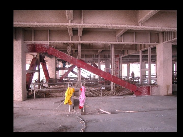
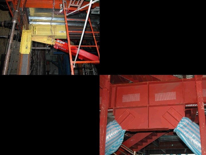
Appendix T Brace Test Specimen: Uniaxial Loading

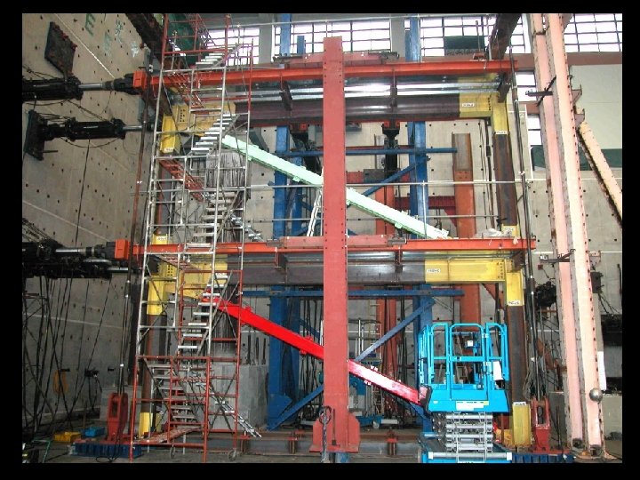
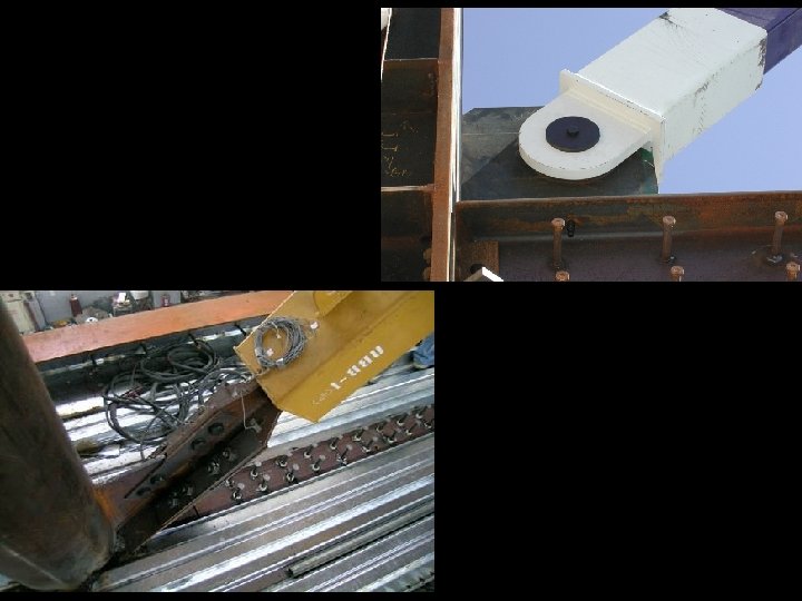
Appendix TSubassemblage Test Specimen: Axial + Rotational Loading

Appendix T Requirements for Test Specimens: Scale 1. Brace Test Specimen 0. 5 [ Pysc ]prototype [ Pysc ]specimen 1. 5 [ Pysc ]prototype 2. Subassemblage Test Specimen [ Pysc ]specimen [ Pysc ]prototype

Appendix TDefinitions: Δb = deformation quantity used to control test = total brace axial deformation for the brace test specimen = total brace end rotation for the subassemblage test specimen Δbm = value of deformation quantity, Δb, corresponding to the design story drift Δby = value of deformation quantity, Δb, at first significant yield of the test specimen

Appendix T When calculating Δbm, the design story drift shall not be taken less that 0. 01 story height Cd Δ E Design story drift = larger of 0. 01 story height

Appendix T Loading Sequence 2 cycles at: Δb = Δby 2 cycles at: Δb = 0. 5 Δbm 2 cycles at: Δb = 1. 0 Δbm 2 cycles at: Δb = 1. 5 Δbm 2 cycles at: Δb = 2. 0 Δbm Continue with additional cycles at Δb = 1. 5 Δbm for the brace test specimen to achieve cumulative axial deformation at least 200 times Δby (not required for subassemblage test specimen)

Appendix T Acceptance Criteria for Test Specimens: • No fracture, brace instability or brace end connection failure • Positive incremental stiffness (no strength degradation) • For Brace Test Specimen: § Tmax Pysc and Cmax Pysc § Cmax 1. 3 Tmax

Appendix T Example of Results for Brace Test Specimen Tmax -2 Dbm Cmax 2 Dbm

16. 2 Bracing Members 16. 2 d Adjusted Brace Strength Tension Adjusted Brace Strength = Ry Pysc Compression Adjusted Brace Strength = Ry Pysc = strain hardening adjustment factor = compression strength adjustment factor Determine from Appendix T brace tests Take Ry = 1. 0 if Psyc is computed using coupon

16. 2 Bracing Members 16. 2 d Adjusted Brace Strength = strain hardening adjustment factor = compression strength adjustment factor Determine from Appendix T brace tests

AISC Seismic Provisions - BRBF 16. 3 Bracing Connections 16. 3 a Required Strength The required strength of bracing connections in tension and compression shall be 1. 1 adjusted brace strength in compression Pu = 1. 1 Ry Pysc 16. 3 b Gusset Plates The design of connections shall include considerations of local and overall buckling. Bracing consistent with that used in the tests upon which the design is based is required.

AISC Seismic Provisions - BRBF 16. 4 Special Requirements Related to Bracing Configuration For V-type and Inverted V-type bracing: (1) Design beams for unbalanced load resulting from the adjusted brace strengths in tension and compression. Take force in tension brace: Ry Pysc Take force in compression brace: Ry Pysc Assume beam has no vertical support between columns.
 D + 0. 5 L")
L wgravity = (1. 2 + 0. 2 SDS) D + 0. 5 L Ry Pysc Beam-to-column connections: simple framing
 D")
Forces acting on beam: L wgravity = (1. 2 + 0. 2 SDS) D + 0. 5 L ( -1) Ry Pysc cos ( -1) Ry Pysc sin

Beam deflection due to unbalanced loads: Δv = vertical beam deflection due to unbalanced load ( -1) Ry Pysc sin When testing braces per Appendix T: Include additional brace elongation resulting from vertical beam deflection when determining Δbm

AISC Seismic Provisions - BRBF 16. 4 Special Requirements Related to Bracing Configuration For V-type and Inverted V-type bracing: (2) Both flanges of beams must be provided with lateral braces to resist computed forces resulting from unbalanced brace forces. Design lateral braces per Appendix 6 of AISC Specification Both flanges of the beam must be braced at the point of intersection of the braces.

AISC Seismic Provisions - BRBF 16. 5 Beams and Columns 16. 5 a Width-Thickness Limitations Beam and column members shall meet the requirements of Section 8. 2 b. Beams and Columns: Seismically Compact b/t ps

16. 5 Beams and Columns 16. 5 b Required Strength The required strength of beams and columns is determined from the adjusted brace strengths and factored gravity loads 1. 2 D + 0. 5 L + 02. S +E 0. 9 D + E "E" from adjusted brace strengths in tension and compression

1. 2 D + 0. 5 L + 0. 2 S or 0. 9 D Ry Pysc Ry Pysc

16. 5 Beams and Columns 16. 5 c Splices Splice Requirements: 1. Satisfy requirements of Section 8. 4 2. Required flexural strength = 0. 5 x (0. 9 Mpc ) 3. Required shear strength = Mpc / H

AISC Seismic Provisions - BRBF 16. 6 Protected Zone The protected zone shall include the steel core of bracing members and elements that connect the steel core to the beams and columns. These protected zones shall satisfy the requirements of Section 7. 4. No welded, bolted, screwed or shot in attachments for perimeter edge angles, exterior facades, partitions, duct work, piping, etc.

16. 6 Protected Zones
 16. 1 Scope 16. 2 Bracing Members 16.")
Section 16 Buckling-Restrained Braced Frames (BRBF) 16. 1 Scope 16. 2 Bracing Members 16. 3 Bracing Connections 16. 4 Special Requirements Related to Bracing Configuration 16. 5 Beams and Columns 16. 6 Protected Zone
- Slides: 59