
By Ali Misaghi Why seismic processing Processing Steps
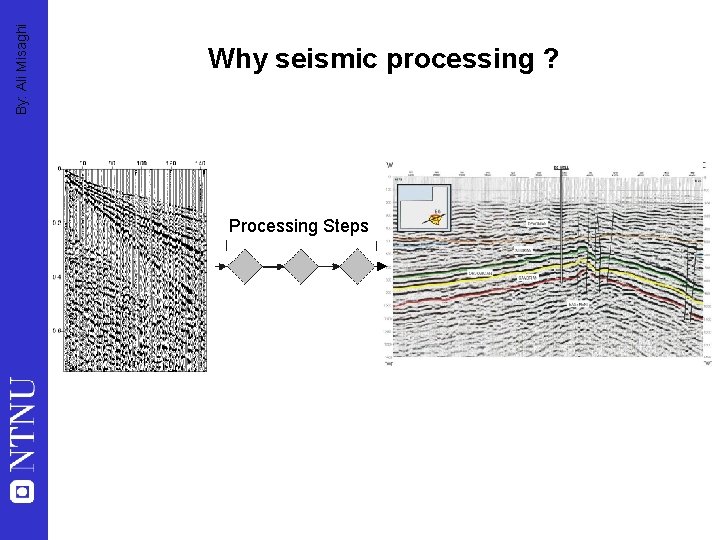
By: Ali Misaghi Why seismic processing ? Processing Steps
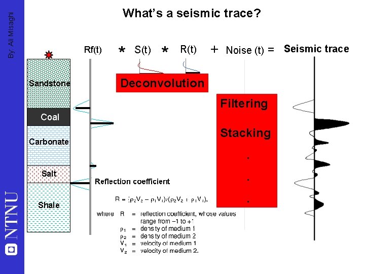
By: Ali Misaghi What’s a seismic trace? Rf(t) Sandstone * S(t) * R(t) + Noise (t) = Seismic trace Deconvolution Filtering Coal Carbonate Stacking. Salt Shale . .
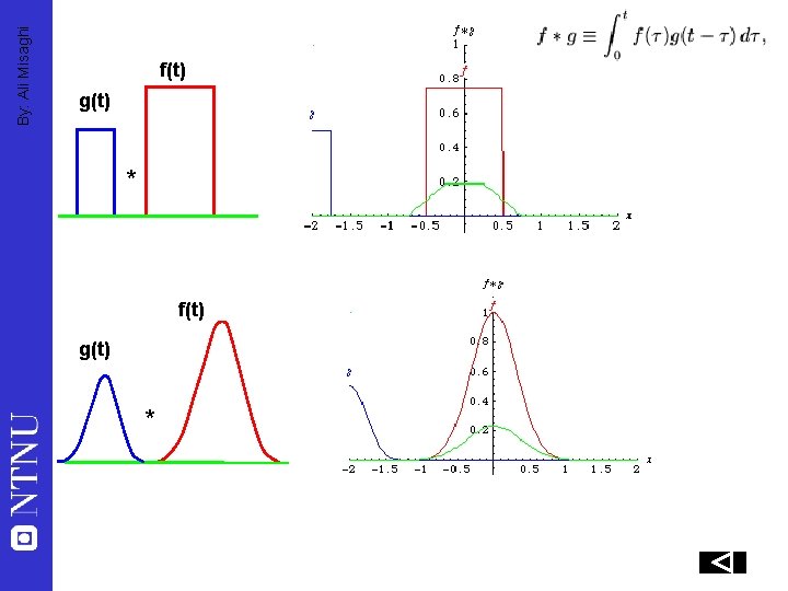
By: Ali Misaghi f(t) g(t) *
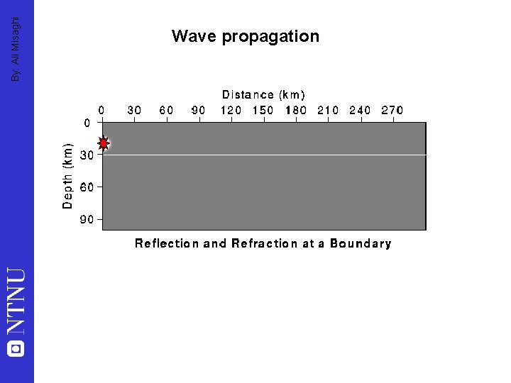
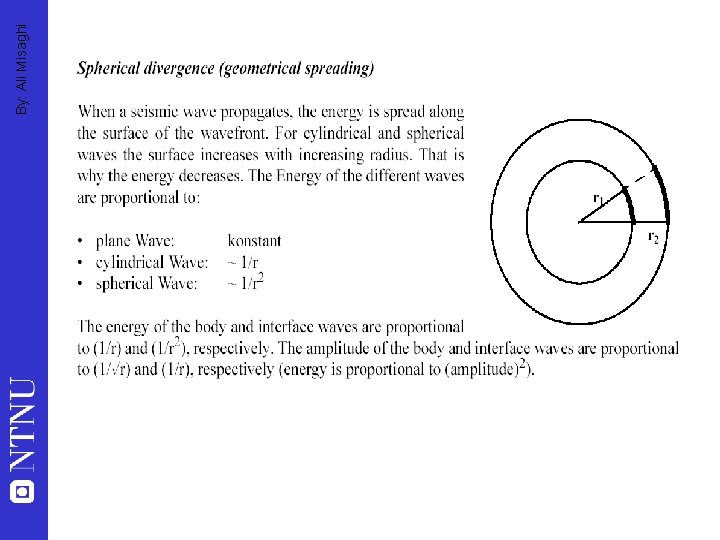
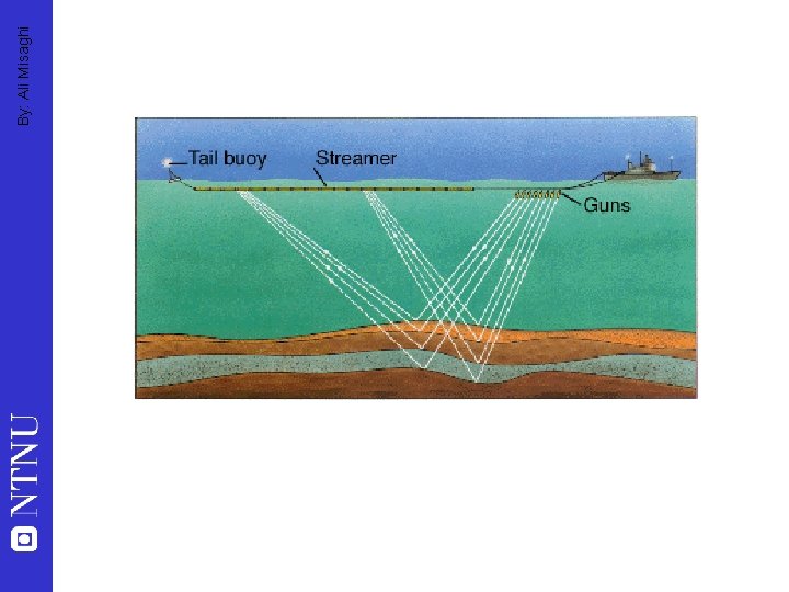
By: Ali Misaghi Wave propagation
By: Ali Misaghi
By: Ali Misaghi
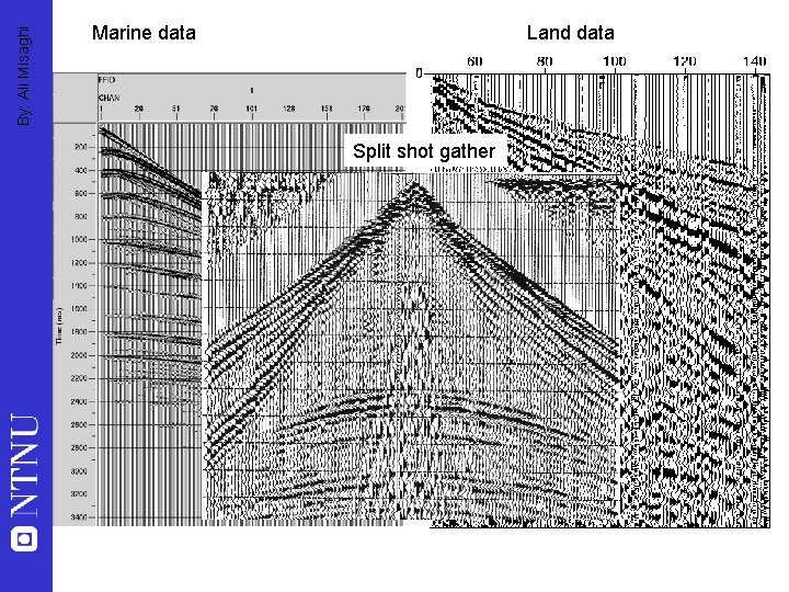
By: Ali Misaghi Marine data Land data Split shot gather
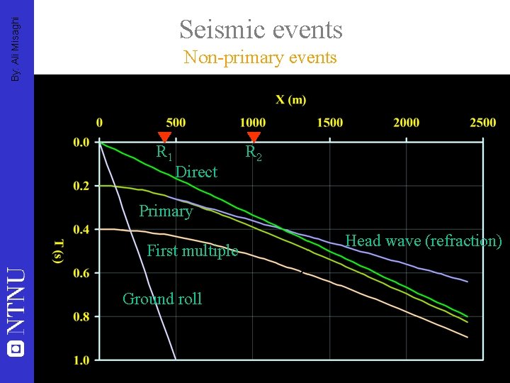
By: Ali Misaghi Seismic events Non-primary events R 1 Direct R 2 Primary First multiple Ground roll Head wave (refraction)
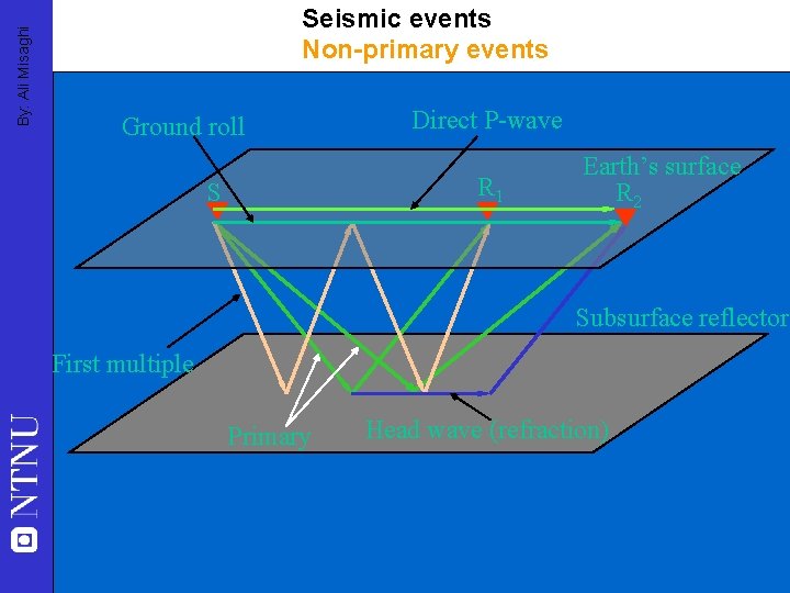
By: Ali Misaghi Seismic events Non-primary events Ground roll Direct P-wave R 1 S Earth’s surface R 2 Subsurface reflector First multiple Primary Head wave (refraction)
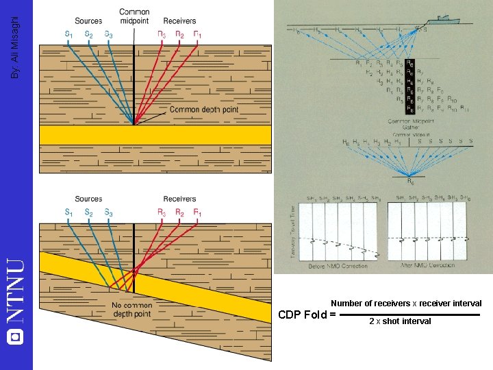
By: Ali Misaghi Number of receivers x receiver interval CDP Fold = 2 x shot interval
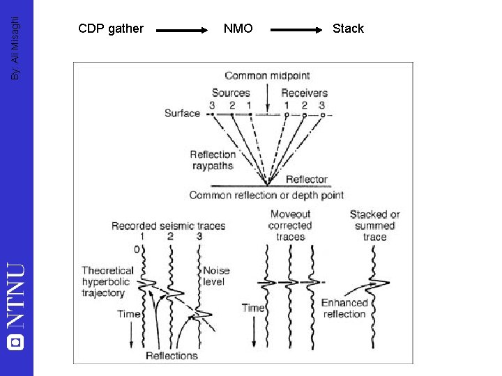
By: Ali Misaghi CDP gather NMO Stack
By: Ali Misaghi Migration “The goal of migration is to make the stacked section appear similar to the geologic cross-section” Oz Yilmaz
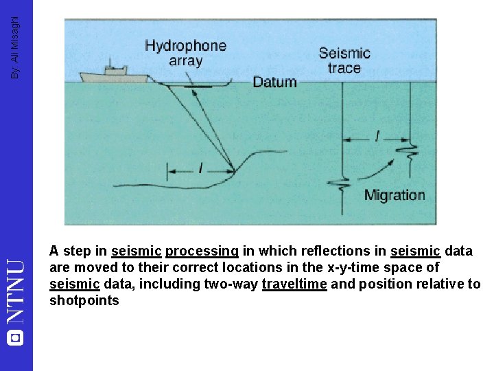
By: Ali Misaghi A step in seismic processing in which reflections in seismic data are moved to their correct locations in the x-y-time space of seismic data, including two-way traveltime and position relative to shotpoints
By: Ali Misaghi
By: Ali Misaghi
By: Ali Misaghi
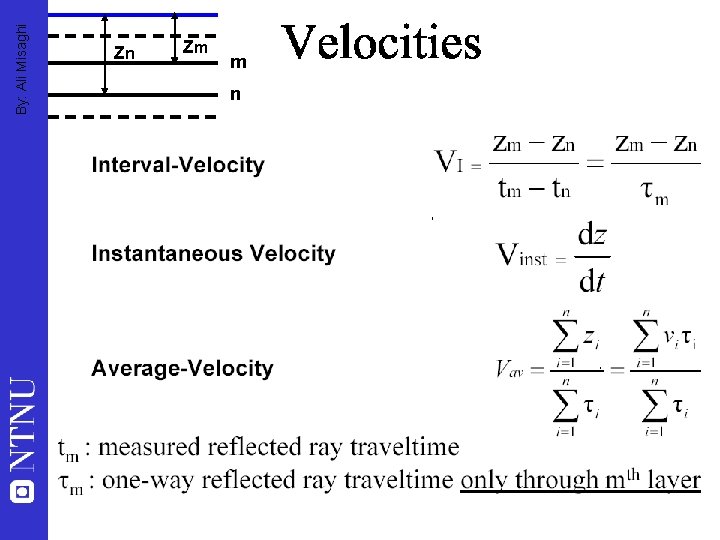
By: Ali Misaghi Zn Zm m n
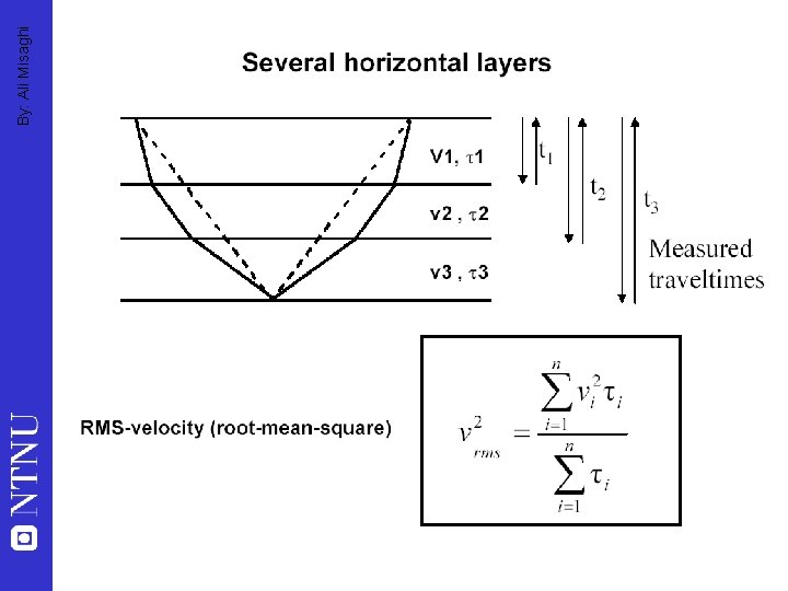
By: Ali Misaghi
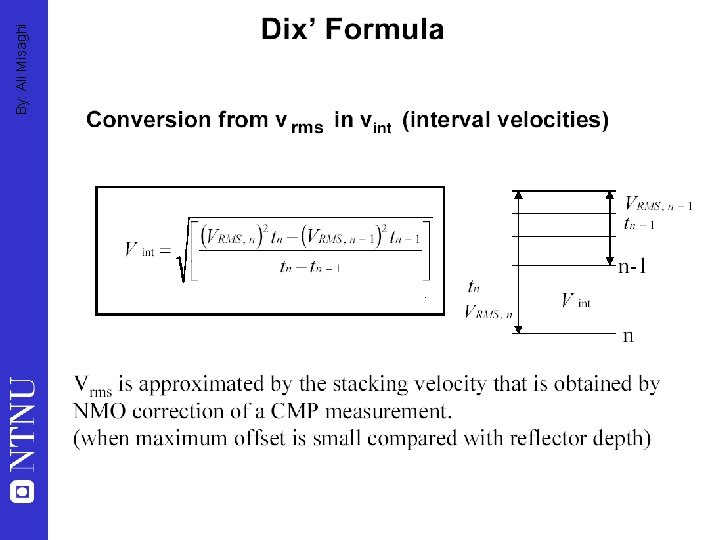
By: Ali Misaghi
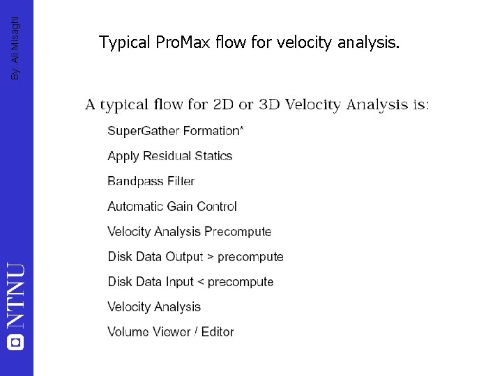
By: Ali Misaghi Typical Pro. Max flow for velocity analysis.
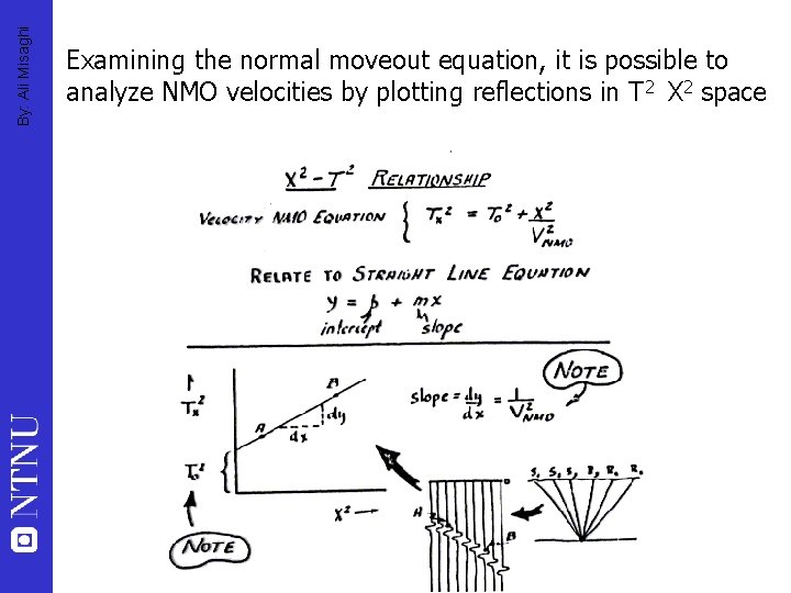
By: Ali Misaghi Examining the normal moveout equation, it is possible to analyze NMO velocities by plotting reflections in T 2 X 2 space
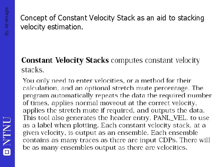
By: Ali Misaghi Concept of Constant Velocity Stack as an aid to stacking velocity estimation.
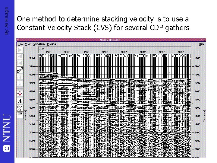
By: Ali Misaghi One method to determine stacking velocity is to use a Constant Velocity Stack (CVS) for several CDP gathers
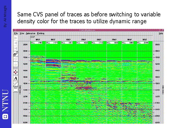
By: Ali Misaghi Same CVS panel of traces as before switching to variable density color for the traces to utilize dynamic range
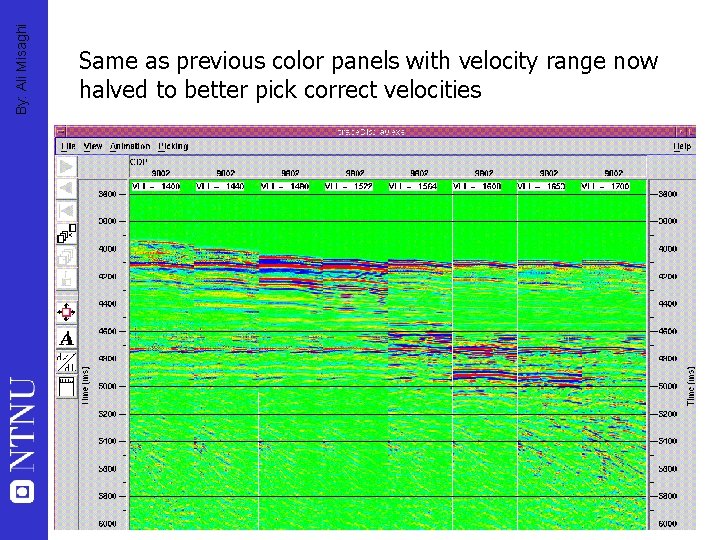
By: Ali Misaghi Same as previous color panels with velocity range now halved to better pick correct velocities
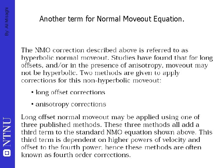
By: Ali Misaghi Another term for Normal Moveout Equation.
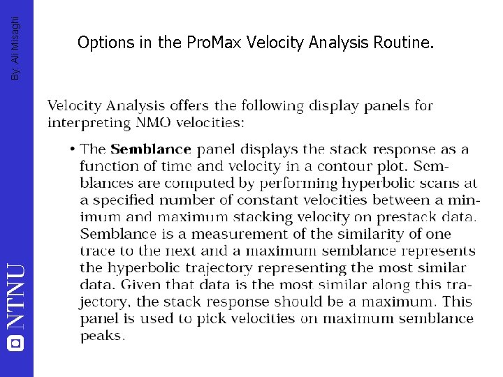
By: Ali Misaghi Options in the Pro. Max Velocity Analysis Routine.
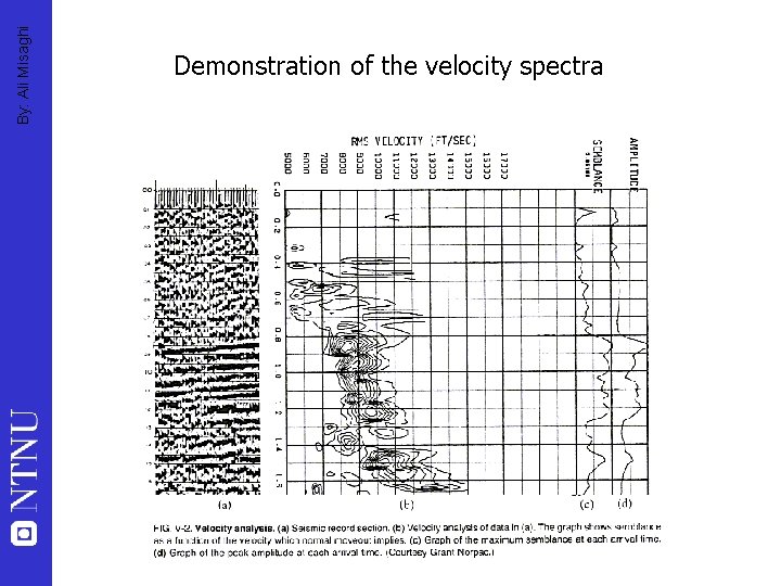
By: Ali Misaghi Demonstration of the velocity spectra
By: Ali Misaghi Options in the Pro. Max Velocity Analysis Routine.
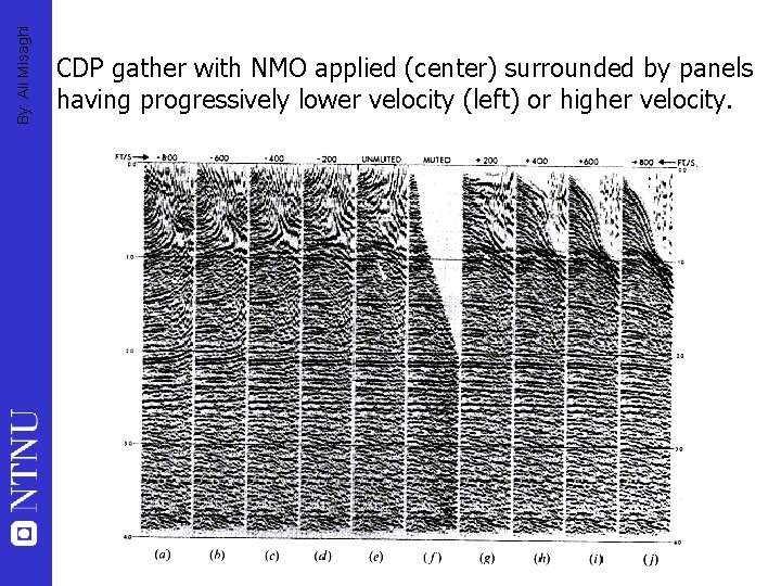
By: Ali Misaghi CDP gather with NMO applied (center) surrounded by panels having progressively lower velocity (left) or higher velocity.
By: Ali Misaghi Options in the Pro. Max Velocity Analysis Routine.
By: Ali Misaghi Options in the Pro. Max Velocity Analysis Routine.
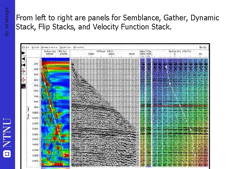
By: Ali Misaghi From left to right are panels for Semblance, Gather, Dynamic Stack, Flip Stacks, and Velocity Function Stack.
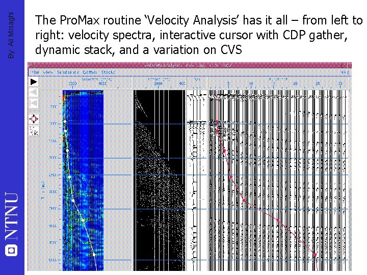
By: Ali Misaghi The Pro. Max routine ‘Velocity Analysis’ has it all – from left to right: velocity spectra, interactive cursor with CDP gather, dynamic stack, and a variation on CVS
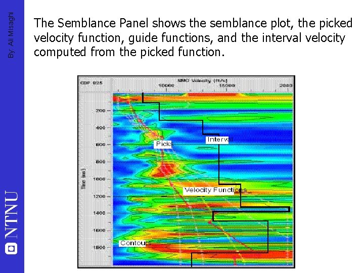
By: Ali Misaghi The Semblance Panel shows the semblance plot, the picked velocity function, guide functions, and the interval velocity computed from the picked function.
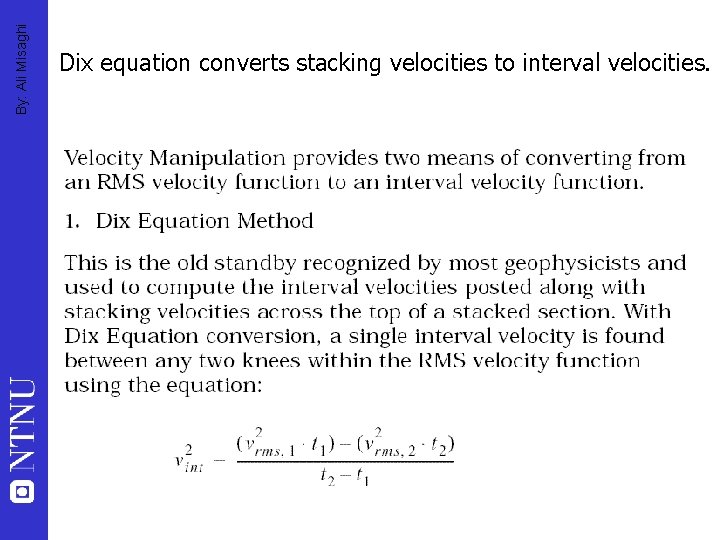
By: Ali Misaghi Dix equation converts stacking velocities to interval velocities.
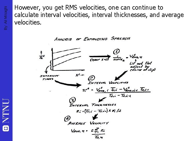
By: Ali Misaghi However, you get RMS velocities, one can continue to calculate interval velocities, interval thicknesses, and average velocities.
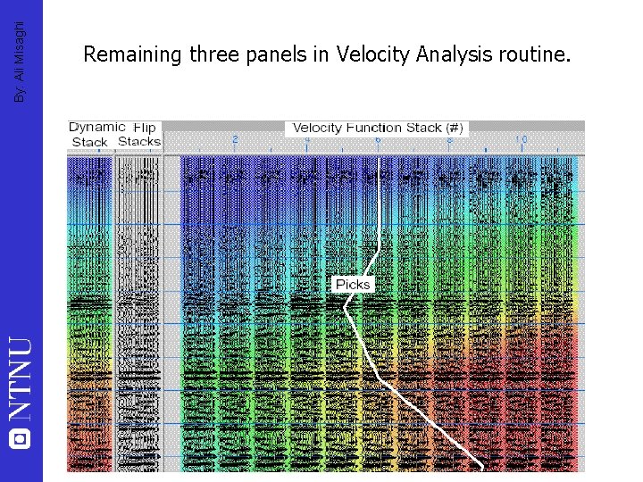
By: Ali Misaghi Remaining three panels in Velocity Analysis routine.
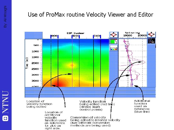
By: Ali Misaghi Use of Pro. Max routine Velocity Viewer and Editor
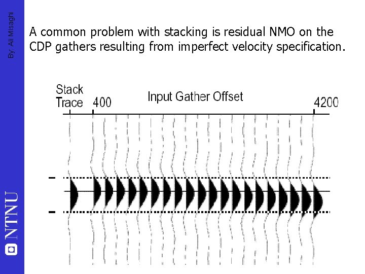
By: Ali Misaghi A common problem with stacking is residual NMO on the CDP gathers resulting from imperfect velocity specification.
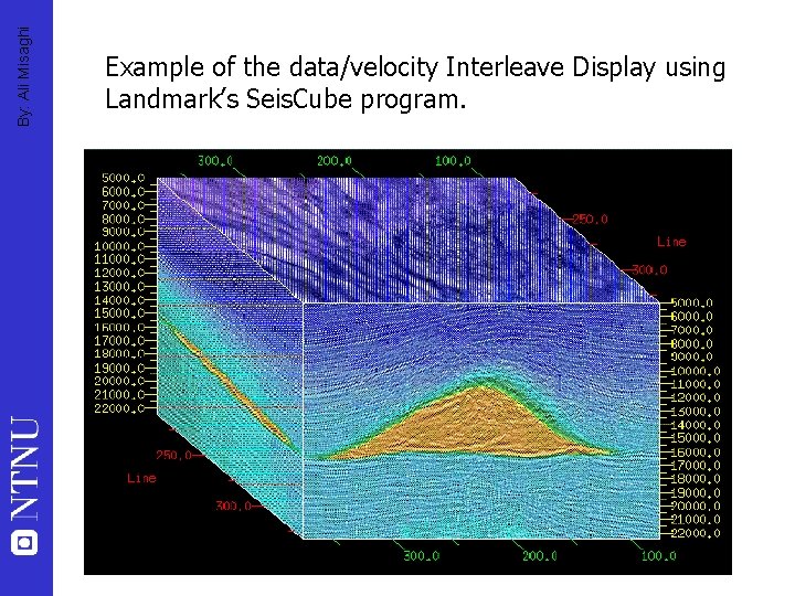
By: Ali Misaghi Example of the data/velocity Interleave Display using Landmark’s Seis. Cube program.
By: Ali Misaghi Progressive Mute Analysis
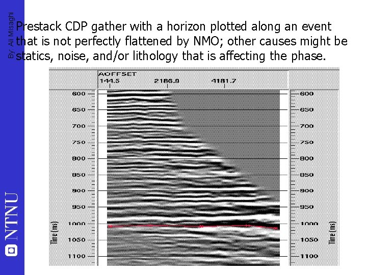
By: Ali Misaghi Prestack CDP gather with a horizon plotted along an event that is not perfectly flattened by NMO; other causes might be statics, noise, and/or lithology that is affecting the phase.
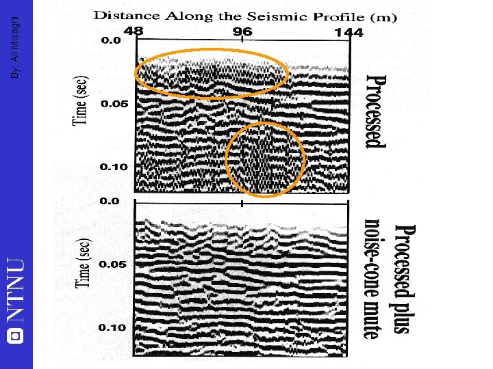
By: Ali Misaghi
By: Ali Misaghi
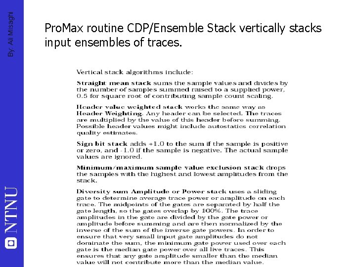
By: Ali Misaghi Pro. Max routine CDP/Ensemble Stack vertically stacks input ensembles of traces.
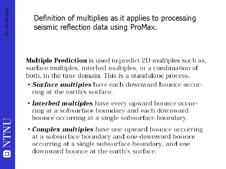
By: Ali Misaghi Definition of multiplies as it applies to processing seismic reflection data using Pro. Max.
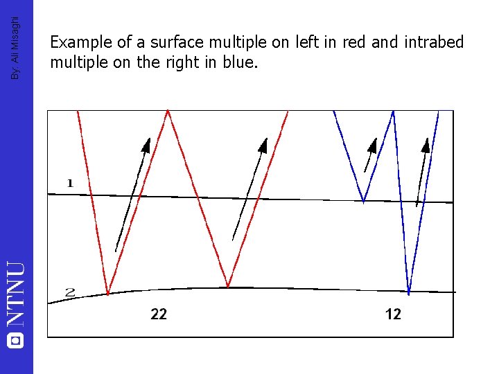
By: Ali Misaghi Example of a surface multiple on left in red and intrabed multiple on the right in blue.
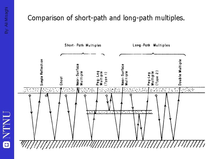
By: Ali Misaghi Comparison of short-path and long-path multiples.
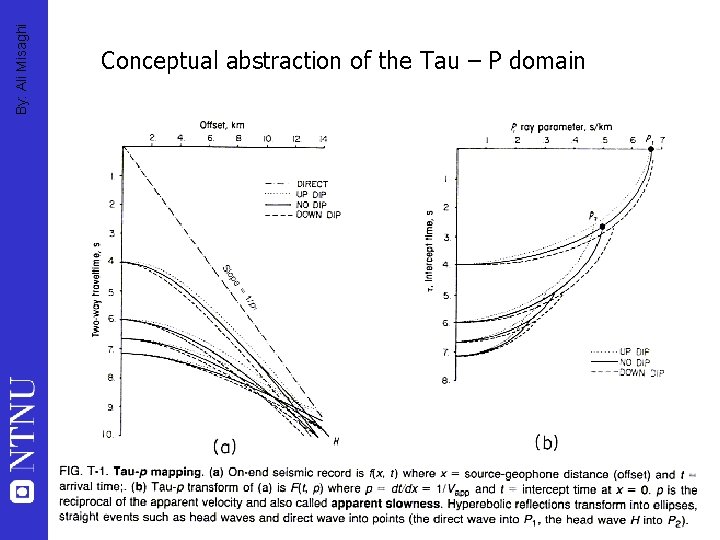
By: Ali Misaghi Conceptual abstraction of the Tau – P domain
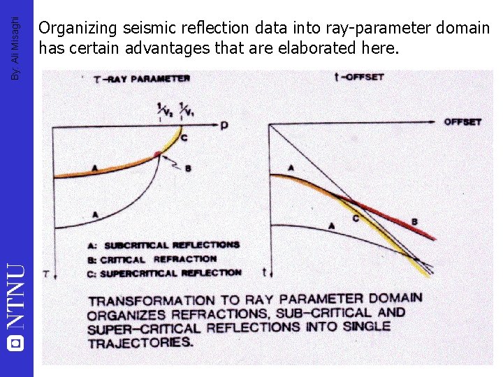
By: Ali Misaghi Organizing seismic reflection data into ray-parameter domain has certain advantages that are elaborated here.
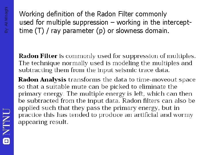
By: Ali Misaghi Working definition of the Radon Filter commonly used for multiple suppression – working in the intercepttime (T) / ray parameter (p) or slowness domain.
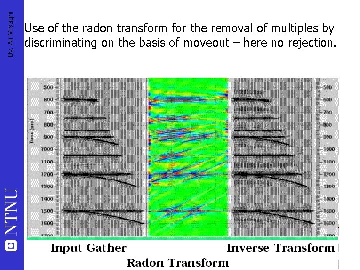
By: Ali Misaghi Use of the radon transform for the removal of multiples by discriminating on the basis of moveout – here no rejection.
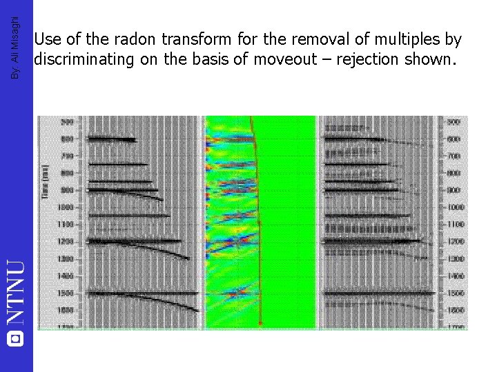
By: Ali Misaghi Use of the radon transform for the removal of multiples by discriminating on the basis of moveout – rejection shown.
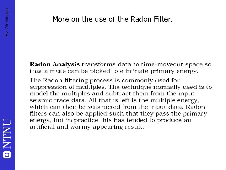
By: Ali Misaghi More on the use of the Radon Filter.

By: Ali Misaghi
By: Ali Misaghi Migration
By: Ali Misaghi Migration “The goal of migration is to make the stacked section appear similar to the geologic cross-section” Oz Yilmaz “Migration is an inversion operation involving rearrangement of seismic information elements so that reflections and diffractions are plotted at their true locations. ” R. E Sheriff
Unmigrated By: Ali Misaghi
Migrated By: Ali Misaghi
By: Ali Misaghi Migration • Collapses diffractions • Corrects for dip – Moves dipping events in the updip direction • Removes effects of surface curvature – “unties the bowties”
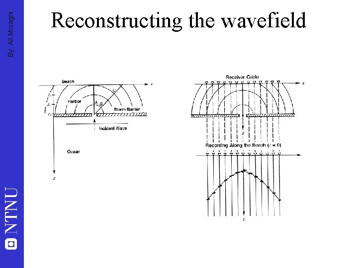
By: Ali Misaghi Reconstructing the wavefield
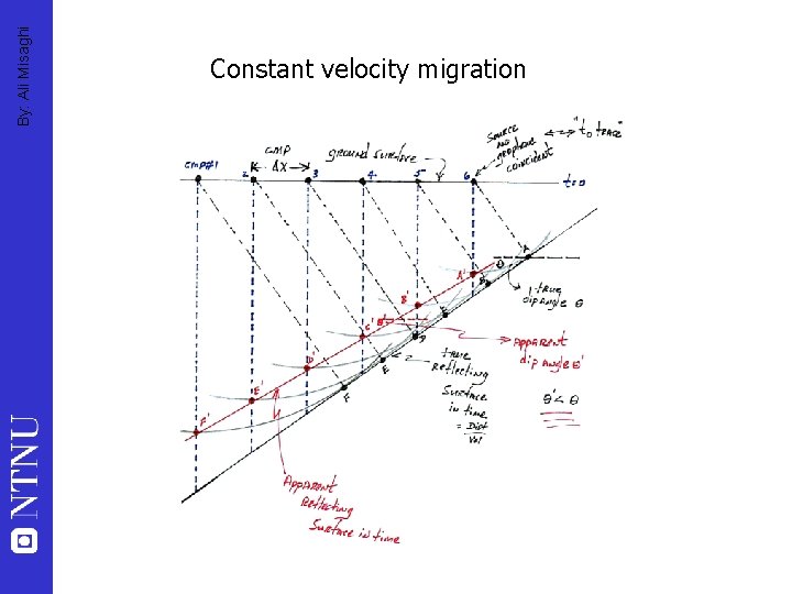
By: Ali Misaghi Constant velocity migration
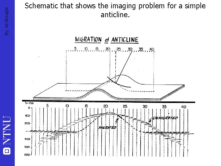
By: Ali Misaghi Schematic that shows the imaging problem for a simple anticline.
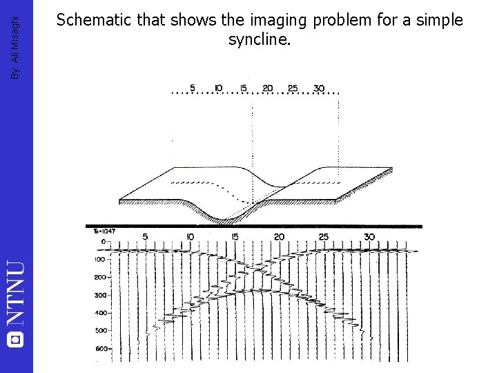
By: Ali Misaghi Schematic that shows the imaging problem for a simple syncline.
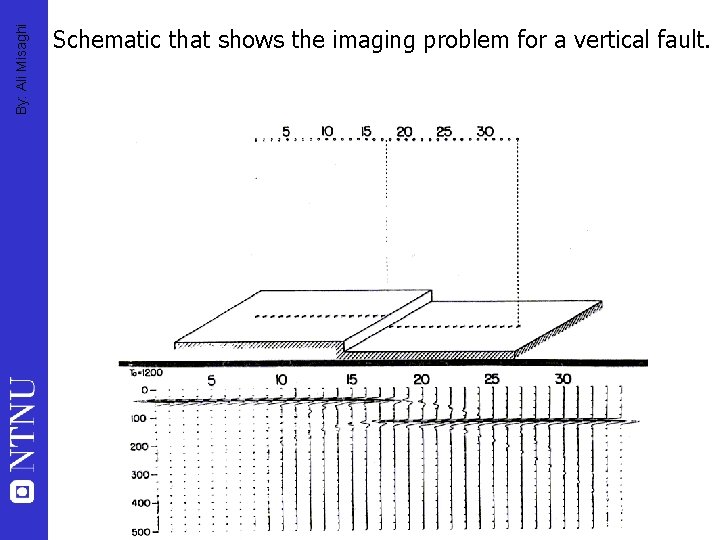
By: Ali Misaghi Schematic that shows the imaging problem for a vertical fault.
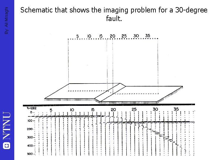
By: Ali Misaghi Schematic that shows the imaging problem for a 30 -degree fault.
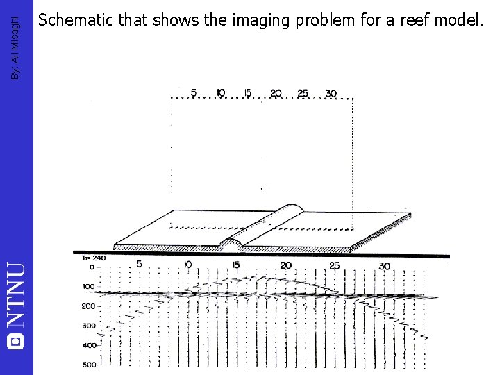
By: Ali Misaghi Schematic that shows the imaging problem for a reef model.
By: Ali Misaghi Migration Methods • Kirchoff migration (diffraction stacking) – integral solution of wave equation • Finite difference method – derivative solution of wave equation • F-K migration – Fourier domain solution of wave equation
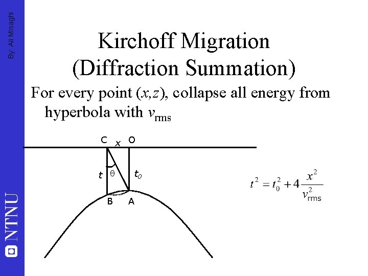
By: Ali Misaghi Kirchoff Migration (Diffraction Summation) For every point (x, z), collapse all energy from hyperbola with vrms C x O t B t 0 A
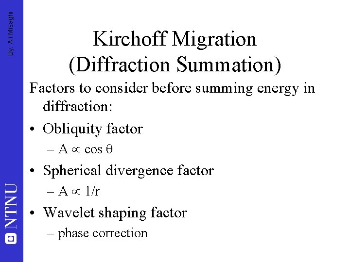
By: Ali Misaghi Kirchoff Migration (Diffraction Summation) Factors to consider before summing energy in diffraction: • Obliquity factor – A cos • Spherical divergence factor – A 1/r • Wavelet shaping factor – phase correction
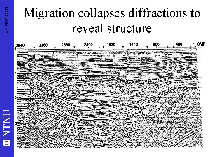
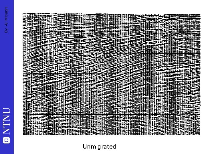
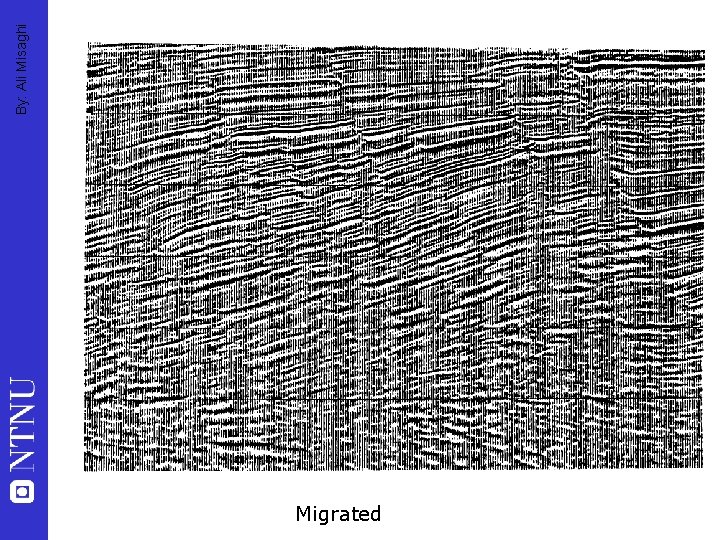
By: Ali Misaghi Migration collapses diffractions to reveal structure
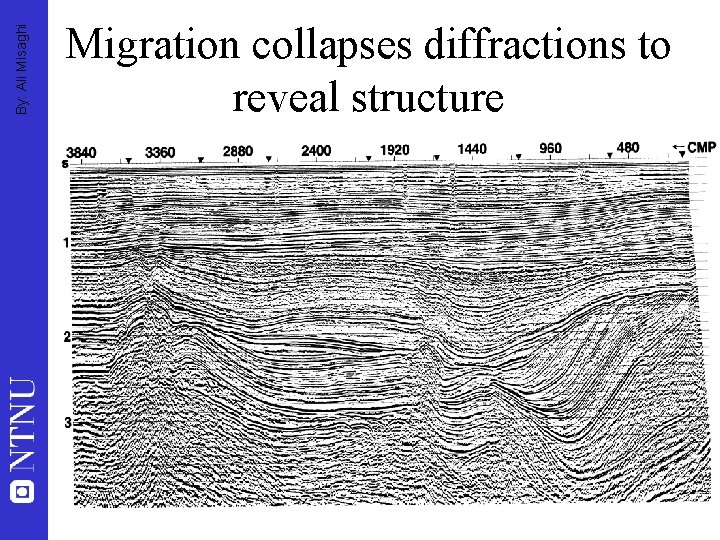
By: Ali Misaghi Migration collapses diffractions to reveal structure
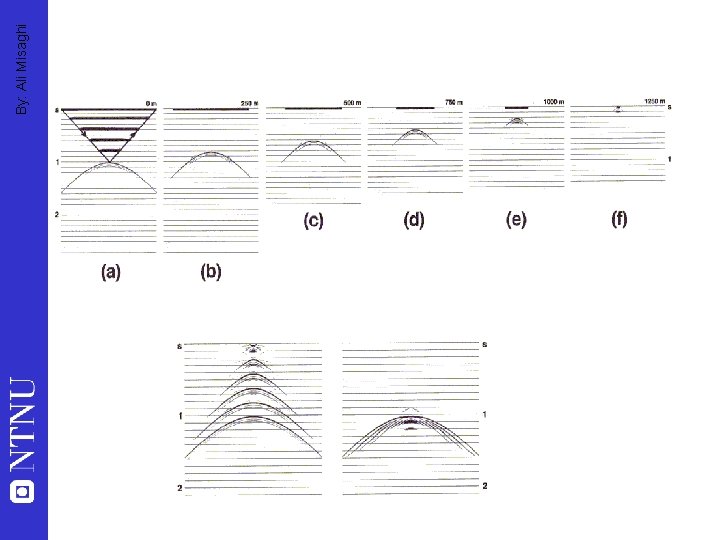
By: Ali Misaghi Finite Difference Migration • Solving the wave equation by stepping down discrete intervals from z=0 • Downward continue wavefield to “exploding reflector” • Define an angle for width of cone for to be included in migration for each point – wider cone more accurate – narrow cone faster, better approximations
By: Ali Misaghi
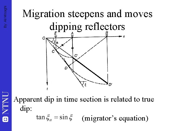
By: Ali Misaghi Migration steepens and moves dipping reflectors Apparent dip in time section is related to true dip: (migrator’s equation)
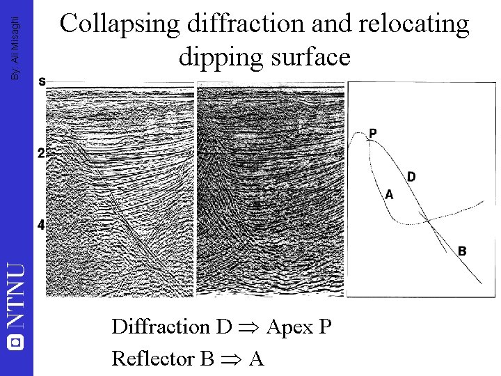
By: Ali Misaghi Collapsing diffraction and relocating dipping surface Diffraction D Apex P Reflector B A
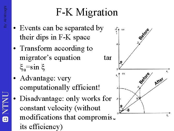
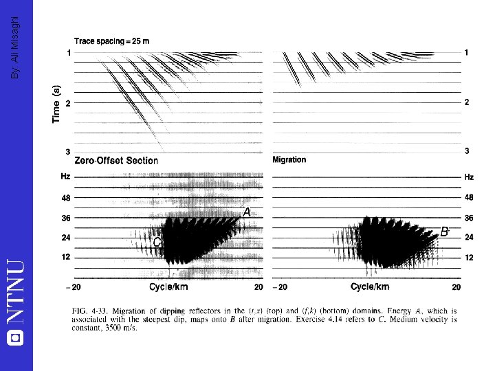
By: Ali Misaghi F-K Migration • Events can be separated by their dips in F-K space • Transform according to migrator’s equation tan a=sin • Advantage: very computationally efficient! • Disadvantage: only works for constant velocity (without modifications that compromise its efficiency)
By: Ali Misaghi
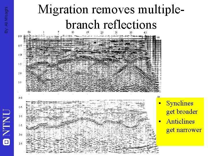
By: Ali Misaghi Migration removes multiplebranch reflections • Synclines get broader • Anticlines get narrower
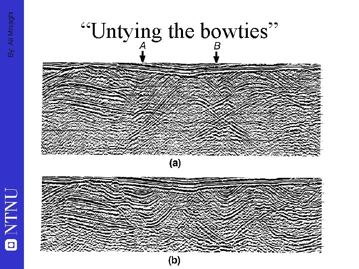
By: Ali Misaghi “Untying the bowties”
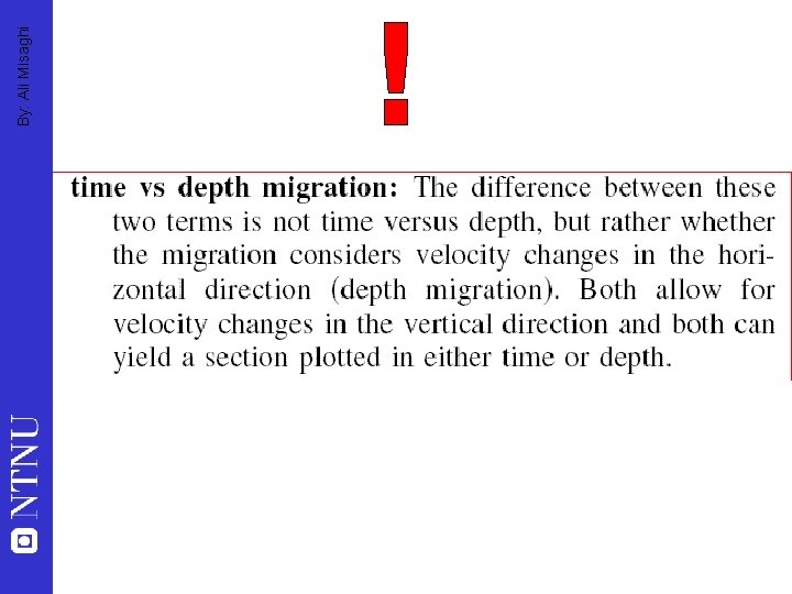
By: Ali Misaghi Limitations of Migration • • • Insufficient spatial resolution will result in aliasing 2 -D slice of 3 -D wavefield (need 3 -D migration!) Edge effects Coherent noise Requires knowledge of velocity structure Time migration methods assume lateral velocity varies slowly (otherwise need depth migration)
By: Ali Misaghi
By: Ali Misaghi 3 -D Processing • Binning by common midpoints in cells on a grid • Migration can be two stage 2 -D migration (in-line direction, then cross-line direction) or full 3 -D wavefield solution • Most other processing operations are unchanged • Display is more difficult (and more fun!)

By: Ali Misaghi
By: Ali Misaghi Why Deconvolution? • Decreases ringing • Increases resolution • Improves appearance of stacked section and makes it easier to interpret • Section is more like the earth and less like the seismic source • Can remove multiples
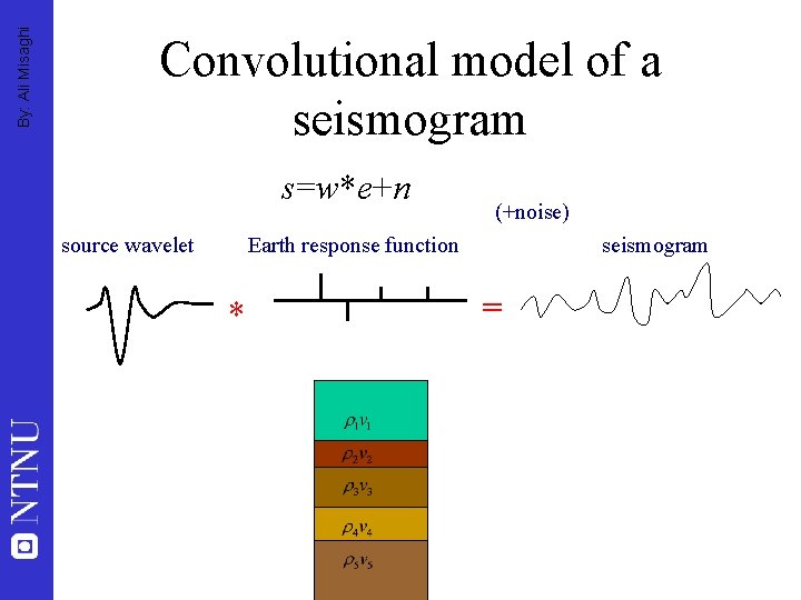
By: Ali Misaghi Convolutional model of a seismogram s=w*e+n source wavelet (+noise) Earth response function * seismogram =
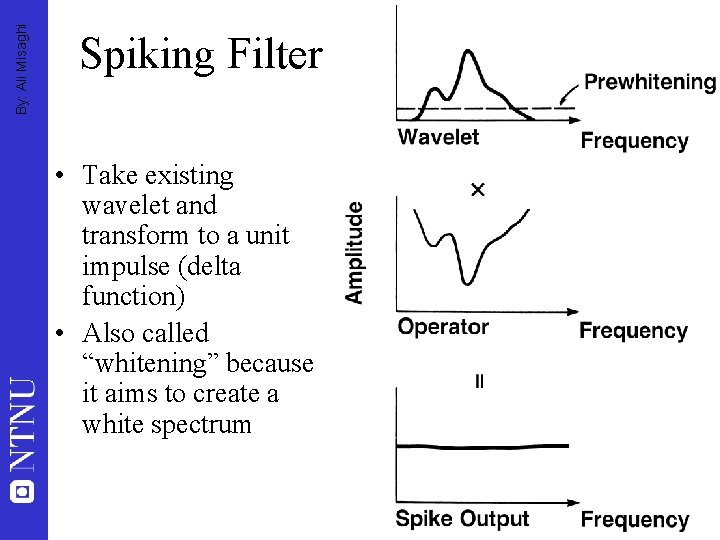
By: Ali Misaghi Spiking Filter • Take existing wavelet and transform to a unit impulse (delta function) • Also called “whitening” because it aims to create a white spectrum
By: Ali Misaghi Predictive Deconvolution • Deconvolution with a built-in time lag • Use to remove – Multiples – Bubble pulse
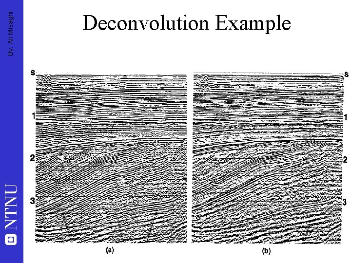
By: Ali Misaghi Deconvolution Example
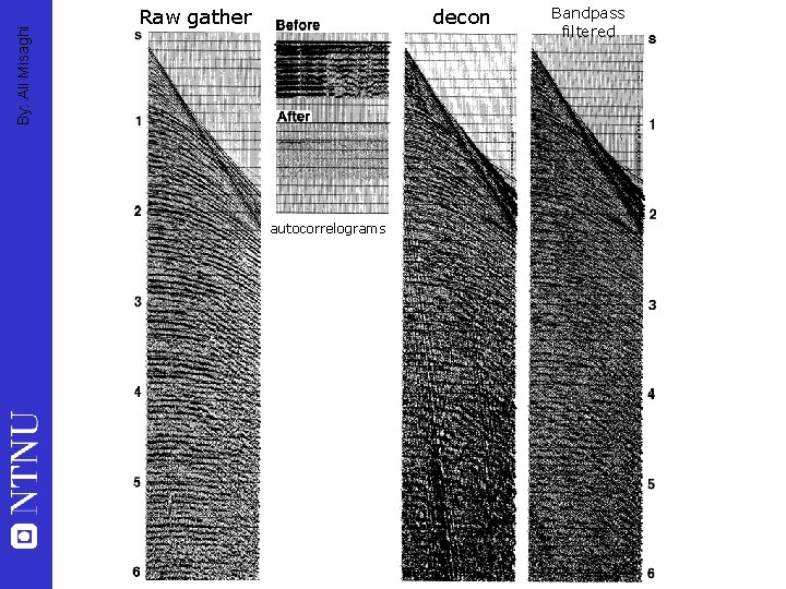
By: Ali Misaghi Raw gather decon autocorrelograms Bandpass filtered
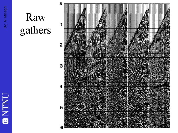
By: Ali Misaghi Raw gathers
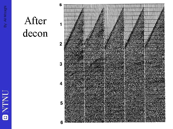
By: Ali Misaghi After decon

By: Ali Misaghi
By: Ali Misaghi Deconvolution • • • Deterministic Inverse Filtering Deghosting Least Squares (Optimum) Filtering Spiking filter Wavelet shaping Predictive Deconvolution
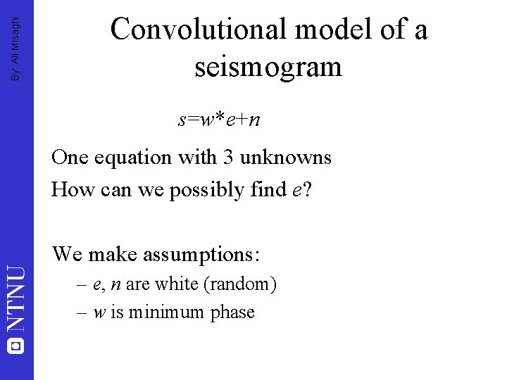
By: Ali Misaghi Convolutional model of a seismogram s=w*e+n One equation with 3 unknowns How can we possibly find e? We make assumptions: – e, n are white (random) – w is minimum phase
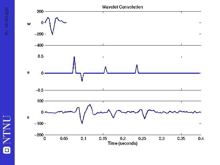
By: Ali Misaghi w e s
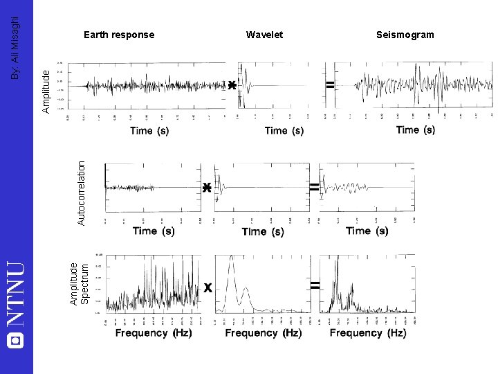
Amplitude Spectrum Autocorrelation Amplitude By: Ali Misaghi Earth response Wavelet Seismogram
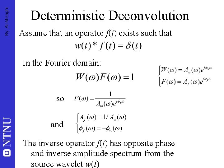
By: Ali Misaghi Deterministic Deconvolution Assume that an operator f(t) exists such that In the Fourier domain: so and The inverse operator f(t) has opposite phase and inverse amplitude spectrum from the source wavelet w(t)
By: Ali Misaghi Deterministic Deconvolution • Assumptions: 1 source wavelet is minimum phase 2 noise is zero 3 wavelet is known • Not true, especially 2 • In practice, the Fourier domain implementation is not very good if assumptions are not met • Other methods are more stable
By: Ali Misaghi Deghosting • Eliminate source & receiver ghosts by considering them as time delayed copies of the source (and with known depths the time delays are known) • Alternatively, hydrophones and geophones with different responses can be combined to eliminate ghosting effects
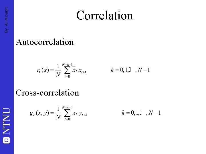
By: Ali Misaghi Correlation Autocorrelation Cross-correlation
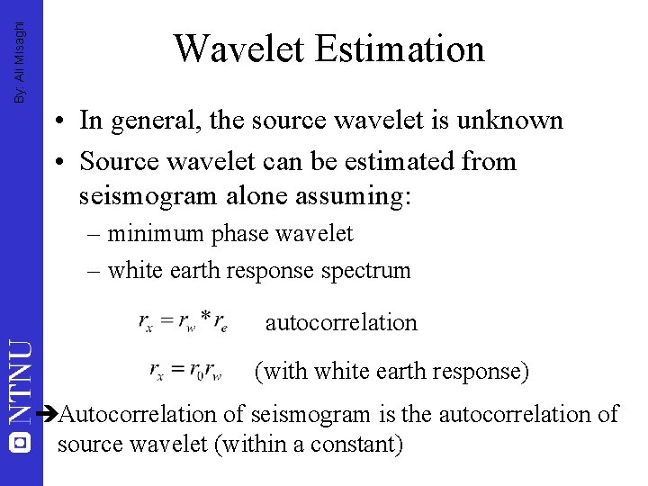
By: Ali Misaghi Wavelet Estimation • In general, the source wavelet is unknown • Source wavelet can be estimated from seismogram alone assuming: – minimum phase wavelet – white earth response spectrum autocorrelation (with white earth response) èAutocorrelation of seismogram is the autocorrelation of source wavelet (within a constant)
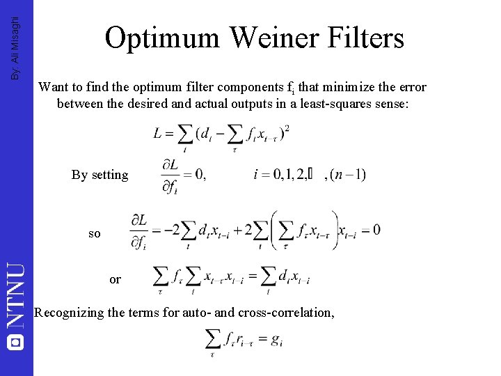
By: Ali Misaghi Optimum Weiner Filters Want to find the optimum filter components fi that minimize the error between the desired and actual outputs in a least-squares sense: By setting so or Recognizing the terms for auto- and cross-correlation,
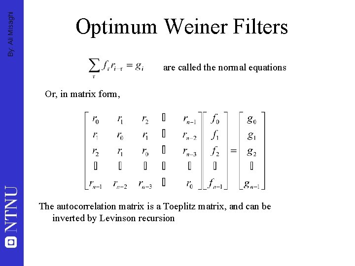
By: Ali Misaghi Optimum Weiner Filters are called the normal equations Or, in matrix form, The autocorrelation matrix is a Toeplitz matrix, and can be inverted by Levinson recursion
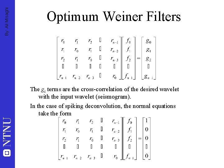
By: Ali Misaghi Optimum Weiner Filters The gi terms are the cross-correlation of the desired wavelet with the input wavelet (seismogram). In the case of spiking deconvolution, the normal equations take the form
By: Ali Misaghi Wavelet Processing • Attempt to shift source wavelet to some other known wavelet, to accomplish one or more of: • Reduce variation of source (between shots, between receivers) • Shift to another known wavelet – e. g. , hydrophone response to match seismometer • Separate wavelet and earth response more clearly
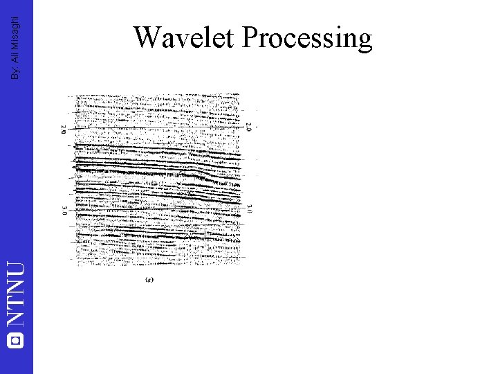
By: Ali Misaghi Wavelet Processing
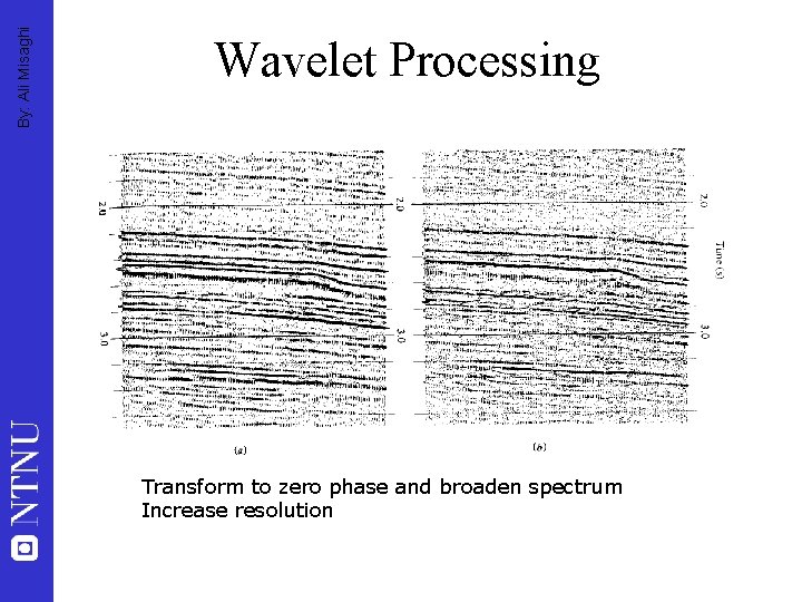
By: Ali Misaghi Wavelet Processing Transform to zero phase and broaden spectrum Increase resolution

By: Ali Misaghi
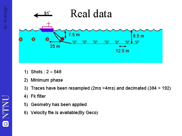
By: Ali Misaghi 91 o Real data 7. 5 m 25 m 8. 5 m 12. 5 m 1) Shots : 2 – 548 2) Minimum phase 3) Traces have been resampled (2 ms >4 ms) and decimated (384 > 192) 4) Fk filter 5) Geometry has been applied 6) Velocity file is available(By Geco)
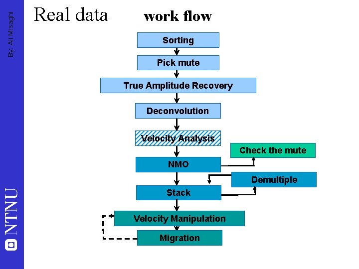
By: Ali Misaghi Real data work flow Sorting Pick mute True Amplitude Recovery Deconvolution Velocity Analysis Check the mute NMO Demultiple Stack Velocity Manipulation Migration
By: Ali Misaghi Real data Project results: -A report: -Explanation of the processing steps with proper and related snap shots(Mute, TAR, Decon, NMO, Demultipling, Stacking, Migration, etc -Final results(a comparison study) -Brute-stack section(s) -Demultipled stack section(s) -Migrated section(s)
- Slides: 113