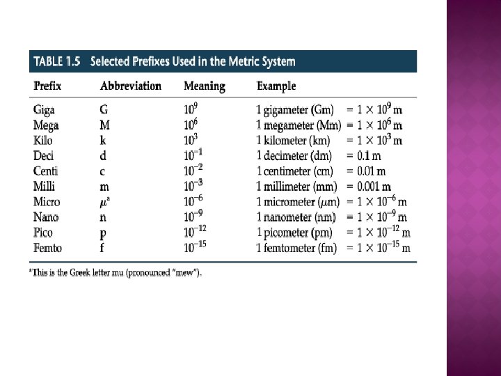
MICROSCOPY Microscopy is the technical field using microscopes


 � Charles Hall, 1730 s: Achromatic lens and second lens of")

 � Abbe Condenser: Abbe's work on a wave theory of microscopic")
 � 19 th/20 th centuries Louis Pasteur invented pasteurization while Robert")


 an employ of Ziess company devised this microscope")


 � Max Knoll and Ernst Ruska 1931: invented the first electron")


 In the TEM high voltage electron beam is produced by")
 and magnifications")


 Ruska (1942) built the first scanning electron microscope (SEM) that")


- Slides: 88
MICROSCOPY � Microscopy is the technical field using microscopes to view samples and objects that can not be seen with unaided eye (objects that are not within the resolution range of the normal eye). There are three well-known types of microscopy: Optical, Transmission Electron and Scanning Electron microscopy.
RESOLUTION � Resolution can be defined as the least distance between two closely placed objects, at which they may be recognized as two separate entities. The best resolution possible in a LM is about 200 nm whereas a typical SEM has 10 nm and TEM has 0. 2 nm.
Resolution power
HISTORY OF MICROSCOPY � � � Long before , in the hazy unrecorded past, a piece of transparent crystal thicker in the middle than at the edges, looked through it, and discovered that it made things look larger. Someone also found that such a crystal would focus the sun's rays and set fire to a piece of parchment or cloth. Magnifiers and "burning glasses" or "magnifying glasses" are mentioned in the writings of Seneca and Pliny the Elder, Roman philosophers during the first century A. D. Spectacles were invented at the end of the 13 th century. They were named lenses because they are shaped like the seeds of a lentil. The earliest simple microscope was merely a tube with a plate for the object at one end a lens which gave a magnification ten times the actual size. These were used to view fleas or tiny creeping things and so were dubbed "flea glasses.
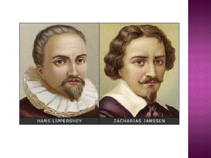
Timeline of the Microscope � � � 4000 years ago: Use of glass lenses and water in a tube in China 3500 years ago: Ancient Egyptians and Romans used glass to magnify objects 14 th century: spectacles were first made in Italy 1656 "an instrument for viewing what is small, " from Gk. micro- small skopion "means of viewing, " from skopein "look at. “ The Greeks gave us the word "microscope 1590: Two Dutch spectacle-makers father-and-son team, Hans and Zacharias Janssen, invented first microscope. 1665: Robert Hooke's famous "Micrographia" was published using the microscope.
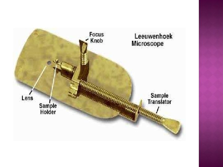
TIMELINE OF THE MICROSCOPE CONT’D � 1675: Anton van Leeuwenhoek, who used a microscope observe insects, bacteria and other objects. to � 1830: Joseph Jackson Lister, used weak lenses together at various distances provided clear magnification. � 1878: Ernst Abbe : mathematical theory linking resolution to light wavelength � 1903: Richard Zsigmondy: invents the ultra microscope, allows for observation below the wavelength of light. � 1932: Frits Xernike’s: Transparent biological material was studied by phase-contrast microscope. � 1938: Ernst Ruska: developed the electron microscope, which enhanced resolution. � 1981: Gerd Binnig and Heinrich Rohrer: 3 -D specimen images possible with the invention of the scanning tunneling microscope
ROBERT HOOKE ANTHONY VAN LEEUWENHOEK
ANCIENT SPECTACLES
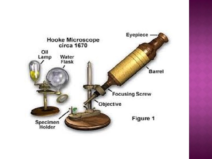
ANCIENT MICROSCOPES Robert Hooks Microscope Made of gold and leather and candle as light source
FIRST DRAWING OF FLEA AND TS OF CORK BY ROBERT HOOKE
OPTICAL COMPOUND MICROSCOPE
CCD CAMERA ATTACHED MICROSCOPE
CCD CAMERA ATTACHED MICROSCOPE WITH COMPUTER
CCD CAMERA ATTACHED MICROSCOPE WITH COMPUTER
OPTICAL MICROSCOPY � Optical or light microscopy involves passing visible light transmitted through or reflected from the sample through a single or multiple lenses to allow a magnified view of the sample. The resulting image can be detected directly by the eye or a photographic plate or captured digitally. The single lens with its attachments, or the system of lenses and imaging equipment, along with the appropriate lighting equipment, sample stage and support, makes up the basic light microscope. The most recent development is the digital microscope, which uses a CCD camera to focus on the exhibit of interest
USES OF OPTICAL MICROSCOPE � Optical microscopy is used extensively in microelectronics, nanophysics, biotechnology, pharmaceutical research, mineralogy and microbiology. � Optical microscopy is used for medical diagnosis, the field of histopathology when dealing with tissues, or in smear tests on free cells or tissue fragments. � In industrial use, binocular microscopes are common. The use of dual eyepieces reduces eye strain associated with long workdays at a microscopy station.
TYPES OF OPTICAL MICROSCOPES � Simple microscope � Compound microscope �Bright field microscope �Dark field microscope �Fluorescence microscope �Phase contrast microscope �Polarized microscope �Confocal microscope �Digital microscope
HISTORY OPTICAL MICROSCOPE � Compound microscope magnified an image by a single lens can be further magnified by a second or more lenses. � First microscope of Antonie van Leeuwenhoek Father of microscope): the specimen was mounted on the top of the pointer, above which lay a convex lens attached to a metal holder. The specimen was then viewed through a hole on the other side of the microscope and was focused using a screw (500 lenses were prepared by grinding gave variable magnifications)
COMPOUND MICROSCOPE (CONT’D) � Charles Hall, 1730 s: Achromatic lens and second lens of different shape and refracting properties realign colors with minimal impact on the magnification of the first lens. � Joseph Lister 1830: solved the problem of spherical aberration (light bends at different angles depending on where it hits the lens) by placing lenses at precise distances from each other. � Ernst Leitz 1863: Introduction of the first revolving turret.
REVOLVING TURRET
COMPOUND MICROSCOPE (CONT’D) � Abbe Condenser: Abbe's work on a wave theory of microscopic imaging developed seventeen objectives lens-three of these were first immersion oil objectives � First microtome was used to enabled thinner samples. � August Kohler 1893: Zeiss employee figured out an unparalleled illumination system known as Kohler illumination corrected by using double diaphragms � Walter Flemming 1879: cell mitosis and chromosomes
COMPOUND MICROSCOPE (CON’T) � 19 th/20 th centuries Louis Pasteur invented pasteurization while Robert Koch discovered his famous or infamous postulates: the anthrax bacillus, the Tuberculosis bacillus and the Cholera vibrio � Unstained specimen has little contrast while stained specimen with dyes have high contrast.
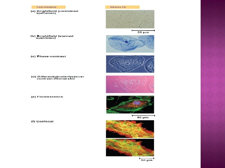
OPTICAL MICROSCOPIC IMAGES
TYPES OF OPTICAL MICROSCOPE � The optical microscope, often referred to as light microscope. They are of two types: � Simple microscope: A simple microscope is a microscope that uses a lens or set of lenses to enlarge an object through angular magnification alone, giving the viewer an erect enlarged virtual image. Simple microscopes are not capable of high magnification. The use of a single convex lens or groups of lenses are still found in simple magnification devices such as the magnifying glass, loupes, and eyepieces for telescopes and microscopes.
PRINCIPLE OF SIMPLE MICROSCOPE
SIMPLE LIGHT MICROSCOPE
Compound microscope: In this microscope objective lens are used close to the object being viewed to collect light which focuses a real image of the object inside the microscope (image 1). That image is then magnified by a second lens or group of lenses (called the eyepiece) that gives the viewer an enlarged inverted virtual image of the object. The use of a compound microscope allows higher magnification, reduced chromatic aberration and exchangeable objective lenses to adjust the magnification. � Now a days the compound optical microscope has digital charge-coupled device (CCD) cameras attached which allow to capture the digital images showing directly on a computer screen without the need for eyepieces. � On 8 th October 2014, the Nobel Prize in Chemistry was awarded to Eric Betzig, William Moerner and Stefan Hell for "the development of super-resolved fluorescence microscopy, " which brings "optical microscopy into the nanodimension". �
PRINCIPLE OF COMPOUND MICROSCOPE
COMPOUND OPTICAL MICROSCOPE
OPTICAL MICROSCOPY � Advantages �Direct imaging with no need of sample pretreatment, the only microscopy for real color imaging. �Fast, and adaptable to all kinds of sample systems, from gas, to liquid, and to solid sample systems, in any shapes or geometries. �Easy to be integrated with digital camera systems for data storage and analysis. � Disadvantages �Low resolution, usually down to only sub-micron or a few hundreds of nanometers, mainly due to the light diffraction limit.
TYPES OF COMPOUND MICROSCOPES � Bright Field Compound Microscope: In a conventional bright field microscope, light from a source is aimed toward a lens beneath the stage called the condenser, through the specimen, through an objective lens, and to the eye through a second magnifying lens, the ocular or eyepiece. We see objects in the light path because natural pigmentation or stains absorb light differentially, or because they are thick enough to absorb a significant amount of light despite being colorless. A Paramecium should show up fairly well in a bright field.
BRIGHT FIELD MICROSCOPE DISSECTING/ STEREO MICROSCOPE
OPTICAL MICROSCOPIC IMAGES
USE OF BRIGHT FIELD MICROSCOPE � To view stained or naturally pigmented specimens such as stained prepared slides of tissue sections or living photosynthetic organisms. � It is useless to view live bacteria, and nonphotosynthetic protists or metazoans, or unstained cell suspensions or tissue sections. � Can be used to view stained bacteria, thick tissue sections, thin sections with condensed chromosome, stained organelles, large protists or metazoans. � Smears, stained blood, negative stained bacteria � Living preparations, wet mounts, unstained pond water, algae and other microscopic plant material.
IMAGE OF LIGHT MICROSCOPE ANIMAL TISSUE ROOT TS
CELL DIVISION IN ONION ROOT TIP CELLS
HUMAN RED BLOOD CELLS, LIKE THOSE OF OTHER MAMMALS, LACK NUCLEI.
� Darkfield Microscope microscopy describes an illumination technique used to enhance the contrast in unstained samples. It works by illuminating the sample with light that will not be collected by the objective lens, and thus will not form part of the image. This produces the classic appearance of a dark, almost black, background with bright objects on it. � The light enters the sample. Most is directly transmitted, while some is scattered from the sample. The scattered light enters the objective lens, while the directly transmitted light simply misses the lens. The scattered light produces the image, while the directly transmitted light is omitted.
PRINCIPLE OF DARK FIELD LM
ADVANTAGES AND DISADVANTAGES OF DARK FIELD LM � Dark field microscopy produces an image with a dark background. � It is used for live and unstained biological samples, such as a smear from a tissue culture or individual, water-borne, singlecelled organisms � The main limitation of dark field microscopy is the low light levels seen in the final image. This means the sample must be very strongly illuminated, which can cause damage to the sample.
DARK FIELD IMAGE OF TISSUE PAPER
Fluorescence microscope � Modern biological microscopy depends on the fluorescent probes for specific structures within a cell. In fluorescence microscopy the sample is illuminated through the objective lens with a narrow set of wavelengths of light. This light interacts with fluorophores in the sample which then emit light of a longer wavelength. This emitted light which makes up the image. � Chemical fluorescent stains, such as 4', 6 -diamidino-2 phenylindole (DAPI) binds to DNA, Rhodamine binds to mitochondria, Fluorescein isothiocyanate (FITC) and Cyanines (Cy 2, Cy 3, Cy 5 and Cy 7) � More recent develoment include immunofluorescence which uses fluorescently labeled antibodies to recognize specific proteins within a sample, and fluorescent proteins like GFP which a live cell can express making it fluorescent. �
FLUORESCENCE MICROSCOPE
IMAGES OF FLUORESCENCE MICROSCOPE
Polarized Microscope � This type microscopy uses plane-polarized light to analyse structures that are birefringent; structures that have two different refractive indices at right angles to one another (e. g. cellulose microfibrils). � Plane-polarized light, produced by a polar, only oscillates in one plane because the polar only transmits light in that plane. � The polarized light microscope has both lenses a polarizer, positioned in the light path somewhere before the specimen, and an analyzer placed in the optical pathway after the objective rear aperture. � Image contrast arises from the interaction of planepolarized light with a birefringent (double-refracting) specimen to produce two individual wave components that are each polarized in mutually perpendicular planes. �
PRINCIPLE OF POLARIZED LIGHT MICROSCOPE
USE OF POLARIZED MICROSCOPE � Polarized light microscopy can be used to measure the amount of retardation that occurs in each direction and so give information about the molecular structure of the birefringent object e. g. cell wall.
POLARIZED LIGHT PATHWAY
BRIGHT, DARK AND POLARIZED LM IMAGES OF TISSUE PAPER Bright Dark Polarized
Phase Contrast Microscope � Zernicka (1941) an employ of Ziess company devised this microscope and win a Nobel Prize in 1953. � The light slows slightly when passing through biological specimens. Differences in the phase of light transmitted and reflected by a specimen to form distinct, contrasting images of different parts of specimens. � The specimen is illuminated by a hollow cone of light coming through a phase annulus in the condenser. Phase contrast objectives must be used, which have a corresponding phase plate. Light rays passing through the specimen are slightly retarded, and further retardation takes place in the phase plate. When these rays combine with rays which have not taken this path, degrees of constructive and destructive interference occur which produce the characteristic light and dark features in the image �
PHASE CONTRAST LIGHT MICROSCOPE
PHASE CONTRAST IMAGE
PHASE CONTRAST IMAGE OF CELL SHOWING NUCLEOLUS, NUCLEUS, CYTOPLASM
� Confocal microscope � In it epifluorescent illumination is used as a scanning laser to illuminate a sample for fluorescence. Problem of conventional light and fluorescence microscopy not only is the plane of focus illuminated, but much of the specimen above and below this point is also illuminated resulting in out-of-focus blur images from these areas. This out-of-focus light leads to a reduction in image contrast and a decrease in resolution. In the confocal microscope, all out-of-focus structures are suppressed at image formation. This is obtained by an arrangement of diaphragms, which, at optically conjugated points of the path of rays, act as a point source and as a point detector respectively. The detection pinhole does not permit rays of light from out-of-focus points to pass through it. The wavelength of light, the numerical aperture of the objective and the diameter of the diaphragm affect the depth of the focal plane. To obtain a full image, the point of light is moved across the specimen by scanning mirrors. The emitted/reflected light passing through the detector pinhole is transformed into electrical signals by a photomultiplier and displayed on a computer monitor � �
PRINCIPLE OF CONFOCAL MICROSCOPE
CONFOCAL MICROSCOPE
CONFOCAL EPIFLUORESCENCE MICROSCOPIC IMAGE An image of a cell stained with fluorescent dyes during metaphase. The mitotic spindle (green) attached to the two sets of chromosomes (blue). All chromosomes but one are already at the metaphase plate
IMAGE OF CONFOCAL MICROSCOPE
IN-SITU HYBRIDIZATION IMAGE OF CONFOCAL MICROSCOPE A mouse fibroblast nucleus in which DNA is stained blue. The distinct chromosome territories of chromosome 2 (red) and chromosome 9 (green) are stained with fluorescent in situ hybridization
� Digital microscope � A digital microscope is a microscope equipped with a digital camera allowing observation of a sample via a computer. Low-powered digital USB microscopes are also commercially available. These are essentially webcams with a highpowered macro lens and generally do not use transillumination. The camera attached directly to the USB port of a computer, so that the images are shown directly on the monitor. � Digital microscopy allows measurements of distances and areas and quantitaton of a fluorescent or histological stain. � Dino Lite: In the 21 st century Dino-Lite Digital microscopes handheld. They offer low power zoom capability with magnification up to 500 x. They have had a marked impact on industrial inspection application.
DIGITAL MICROSCOPE
CARE OF THE MICROSCOPE � � � � Everything on a good quality microscope is unbelievably expensive, so be careful. Hold a microscope firmly by the stand, only. Never grab it by the eyepiece holder, for example. Hold the plug (not the cable) when unplugging the illuminator. Since bulbs are expensive, and have a limited life, turn the illuminator off when you are done. Always make sure the stage and lenses are clean before putting away the microscope. NEVER use a paper towel, a kimwipe, your shirt, or any material other than good quality lens tissue or a cotton swab to clean an optical surface. Be gentle! You may use an appropriate lens cleaner or distilled water to help remove dried material. Organic solvents may separate or damage the lens elements or coatings. Cover the instrument with a dust jacket when not in use. Focus smoothly; don't try to speed through the focusing process or force anything.
ELECTRON MICROSCOPE (EM) � Max Knoll and Ernst Ruska 1931: invented the first electron microscope � EM transmits a beam of electrons instead of light through the specimen. The subsequent interaction of the beam of electrons with the specimen is recorded and transformed into an image
RESOLUTION LIMIT OF ELECTRON MICROSCOPE
ELECTRON MICROSCOPE � An EM uses a beam of accelerated electrons whose wavelength can be up to 100, 000 times shorter than the photons of visible light. � A high powered EM can achieve 100 pm resolution and magnification of 10, 000 x whereas a light microscopes has 200 nm resolution and magnification below 2000 x. � EM has electrostatic and electromagnetic lenses instead of glass lens to control the electron beam and focus it to form an image. � Two types of electron microscopes: � Transmission Electron Microscope (TEM) � Scanning Electron Microscope (SEM)
USE OF EM � EMs are used to investigate the ultrastructure of a wide range of biological and inorganic specimens including microorganisms, cells, large molecules, biopsy samples, metals and crystals. � Industrially, the EM is used for quality control and failure analysis
TRANSMISSION ELECTRON MICROSCOPE (TEM) In the TEM high voltage electron beam is produced by an electron gun, commonly fitted with a tungsten filament cathode as the electron source. � The electron beam is accelerated by an anode and focused by electrostatic and electromagnetic lenses, and transmitted through the specimen. � When it emerges from the specimen, the electron beam carries information about the structure of the specimen that is magnified by the objectives lens system. The magnified image is projecting onto a fluorescent viewing screen coated with a phosphor or scintillator material such as zinc sulfide. � Alternatively, the image can be recorded by exposing a photographic film or a fiber optic light-guide to the CCD (charge-coupled device) camera. � In modern TEMs the image is detected by the digital camera and displayed on a monitor or computer. �
� High resolution TEM has resolution of 0. 5 angstrom (50 pm) and magnifications above 50 million times. The ability to determine the positions of atoms within materials has made the HRTEM an important tool for nano-technologies research and development. � The major disadvantage of the TEM is the need for extremely thin sections of the specimens, (100 nanometers). Biological specimens are typically required to be chemically fixed, dehydrated and embedded in a polymer resin to stabilize them sufficiently to allow ultrathin sectioning. Sections of biological specimens, organic polymers and similar materials may require special treatment with heavy atom like lead in order to achieve the required image contrast.
TRANSMISSION ELECTRON MICROSCOPE
Electron path of TEM
TRANSMISSION ELECTRON MICROSCOPE
TEM MICROGRAPHS CYTOPLASM NUCLEUS
TEM MICROGRAPH
ELECTRON MICROGRAPH Ongoing gene transcription of ribosomal RNA illustrating the growing primary transcripts. "Begin" indicates the 5’ end of the DNA, where new RNA synthesis begins; "end" indicates the 3’ end, where the primary transcripts are almost complete.
SCANNING ELECTRON MICROSCOPE (SEM) Ruska (1942) built the first scanning electron microscope (SEM) that transmits a beam of electrons across the specimen. � SEM can achieve magnification levels of up to 2 million times � The SEM produces images by probing the specimen with a focused electron beam that is scanned across a rectangular area of the specimen. When the electron beam interacts with the specimen, it loses energy. The lost energy is converted into alternative forms such as heat, emission of low-energy secondary electrons and high-energy backscattered electrons, light emission, all of which provide signals carrying information about the properties of the specimen surface, such as its topography and composition. �
� The image was constructed from signals produced by a secondary electron detector. Generally, the image resolution of an SEM is poorer than that of a TEM. � SEM produces surface image of samples that can be up to many centimeters in size and has a great depth of field, and produce images of three-dimensional shape of the sample.
SCANNING ELECTRON MICROSCOPE
SCANNING ELECTRON MICROSCOPE
SEM MICROGRAPHS EYE OF FLY ROD SHAPED BACTERIA
SEM MICROGRAPHS ANT POLLEN GRAINS
SEM IMAGE OF TS OF LEAF
COMPARISON OF LIGHT, ELECTRON AND SCANNING ELECTRON MICROSCOPES