WEATHERING PROPERTIES PERMANENCE PROPERTIES The property of a



- Slides: 146

WEATHERING PROPERTIES

PERMANENCE PROPERTIES The property of a plastic which describes its resistance to deterioration and change in characteristics with time and environment comes under permanence properties. Corporate Training & Planning 2

WATER ABSORPTION & SOLUBILITY DEFINITION § Ability of plastics to absorb the water when immersed in water, it is directly related to the square root of the immersion time. SIGNIFICANCE § Test results indicates the effect of exposure of plastics to water or humid condition where the moisture content of a plastic is very intimately related to properties such as electrical insulation resistance, dielectric losses, mechanical strength, appearance, and dimensions etc. § Selection of material for specific applications. § The test results can be used as a database for the development of new materials/products. Corporate Training & Planning 3

WATER ABSORPTION & SOLUBILITY TEST METHOD • ASTM D 570: Standard test method for Water Absorption of Plastics • ISO 62: Determination of water absorption of plastics. • JIS K 7209: Testing Methods for Water and Boiling Water Absorption of Plastics. • DIN 53495: Testing of Plastics; Determination of water absorption Corporate Training & Planning 4

WATER ABSORPTION & SOLUBILITY TEST SPECIMEN • A minimum of three specimens shall be tested for each sample; the specimen shall be prepared according to the given dimension (Table 1) to the nearest 0. 025 mm Table 1: Specimen dimension as per the product 1. Moulded plastic Dish of 50. 8 mm in diameter and 3. 2 mm in thickness 2. Sheet Bar length 76. 2 mm. width 25. 4 mm, 3. 2 mm thickness is preferred if moulded 3. Rod 25. 4 mm Long, 25. 4 mm in diameter and 12. 7 mm long for larger diameter 4. Tube 76 -mm in diameter and 25. 4 mm in length, for greater diameter tube same dimension specimen shall be cut from the surface. Corporate Training & Planning 5

WATER ABSORPTION & SOLUBILITY CONDITIONING : • Specimen shall be dried in an oven for 24 h at 50 ± 30 C, cooled in desiccators and immediately weigh to the nearest 0. 001 g. Note: In case of phenolic laminated plastics and other plastics whose water absorption value not affected up to 1100 C, shall be dried in an oven for 1 h at 1100 C. INSTRUMENTS/ APPARATUS • Weighing machine: up to 0. 001 g precision • Dimension Measuring instrument: up to 0. 025 mm precision • Oven: up to 150 0 C with ± 10 C precision REAGENTS : • Anhydrous calcium chloride (dried at 2000 C) and distilled water. Corporate Training & Planning 6

WATER ABSORPTION & SOLUBILITY PROCEDURE The standard conditions of immersion of test specimens are as follows: • Twenty four Hour Immersion: the conditioned specimen shall be placed in a container of distilled water maintained at a temperature 23 ± 10 C. At the end, the specimen shall be removed from the water and all surface water wiped off with dry cloth, and weighed to the nearest 0. 001 g immediately. • Two Hours Immersion at 23 ± 10 C for the material having higher water absorption. • Repeated Immersion at 23 ± 10 C: specimens may be weighed to the nearest 0. 001 g after for 2 h immersion, re-immersed in water and weighed again after 24 h. Corporate Training & Planning 7

WATER ABSORPTION & SOLUBILITY PROCEDURE • Long Term Immersion: repeat the procedure (a) in a sequence of 24 h, one week, two weeks up to saturation (until the increase in weight per two week, until the average increase in weight is less than 1% of the total increase in weight or 5 mg) • Two Hours boiling water Immersion: at the end of 120 ± 4 minutes specimen shall be removed from water and cooled in distilled water maintained at room temperature. • Half an hour boiling water immersion for the material having relatively high rate of absorption. • Immersion at 50 ± 10 C for 48 ± 1 h, cooled in water before weighing shall be omitted. Corporate Training & Planning 8

WATER ABSORPTION & SOLUBILITY PROCEDURE RECONDITIONING : • When the materials are known and contain any appreciable amount of water soluble ingredients, the specimens after immersion shall be weighed and then reconditioned for the same time & temperature as used in the original drying period. Then this shall be cooled in desiccators and reweighed immediately. If the reconditioned weight is lower than the conditioned weight, the difference shall be considered as water soluble matter lost during the immersion test. For such materials the water absorption value shall be taken as the sum of the increase in weight on immersion and of the weight of the water soluble matter. Corporate Training & Planning 9

WATER ABSORPTION & SOLUBILITY CALCULATION : % Water absorption = % increase in weight during immersion. In the case of plastics having water soluble ingredient % Water absorption = % increase in weight during immersion + % soluble matter Where, Conditioned weight – just after conditioning of specimen Wet weight – Specimen weigh after Immersion in water Corporate Training & Planning 10

WATER ABSORPTION & SOLUBILITY RESULT – – – Results can be expressed in terms of % Water absorption % Water soluble matter Dimension of specimen before and after if required Warping, cracking or change in appearance of specimen FACTORS INFLUENCING – Thickness of the specimen – Test condition: Temperature, Time (with in saturation) Corporate Training & Planning 11

WATER ABSORPTION & SOLUBILITY • CASE STUDY 1: Water absorption of different grade of Nylon in investigated at 50 % relative humidity and at saturation.

WATER ABSORPTION & SOLUBILITY CASE STUDY 1: Water absorption of different polymers at 24 hr and saturation is compared below Property Units ABS Noryl UHMW Acetal PET Water Absorption (24 Hours) % 0. 3 0. 07 0. 01 0. 25 0. 7 Water Absorption (Saturation) % 0. 7 0. 2 0. 01 0. 9 0. 5

CHEMICAL RESISTANCE Definition • The resistance of plastics to chemical reagents (acids, bases, solvents, fuels), measured in terms of change in weight, dimension, appearance and strength properties after exposure to reagents at specified temperature and stress conditions for a stipulated period of time. Significance • The result obtained provides basis for standardization and serve as a guide to compare the relative resistance of various plastics to typical chemical reagents. • Selection of plastics for specific applications. Corporate Training & Planning 14

CHEMICAL RESISTANCE TEST METHOD • ASTM D 543: standard practice for evaluating the resistance of plastics to chemical reagents. • ASTM D 4398: Standard Test Method for Determining the Chemical Resistance of glass Fibre-Reinforced Thermosetting Resins by One-Side Panel Exposure. • ASTM C 581: Standard Practice for Determining Chemical Resistance of Thermosetting Resins Used in Glass-Fibre-Reinforced Structures Intended for Liquid Service. • ASTM D 1239: Standard Test Method for Resistance of Plastic Films to Extraction by Chemicals • ISO 175 Plastics: Determination of resistance to liquid chemicals • JIS K 7114: Testing Method for Evaluation of Resistance of Plastics to Corporate Training & Planning Chemical Substance. 15

CHEMICAL RESISTANCE TEST SPECIMEN Table 2: Specimen dimension as per the products • 1. Moulded & extruded plastics Dish of 50. 8 mm in diameter and 3. 175 mm in thickness 2. Sheet material Bar length 76. 20 mm. width 25. 40 mm, 3. 175 mm thickness is preferred if moulded For the effect of chemicals on specific properties (e. g. mechanical), specimen dimension shall be taken as per the standard related to the properties. CONDITIONING : • Specimen shall be conditioned for a minimum period of 40 h at 23 ± 20 C and 50 ± 5% Relative Humidity. Corporate Training & Planning 16

CHEMICAL RESISTANCE INSTRUMENTS / APPARATUS : – Weighing balance: up to 0. 001 g precision – Dimension Measuring instrument: up to 0. 025 mm precision – Strain Jig: capable of supplying known amount of strain to the test specimen. – Testing devises: to check the change in mechanical or other required properties. REAGENTS : – Required Chemicals as per end use applications and distilled water. Corporate Training & Planning 17

CHEMICAL RESISTANCE PROCEDURE : A. Weight & Dimension changes – Weigh the each conditioned specimen and measure its thickness at the center, length and width or two diameters at right angles to each other to the nearest 0. 025 mm. – Place the specimens in a container and allow the specimens to be totally immersed in a fresh reagent for seven days at the standard laboratory environment. – Stir the reagents every 24 h by suitable means. – After 168 hours, remove the specimens from the reagents and weigh immediately. – After weighing, wash with running water, wipe and dry with filter paper carefully, then recondition the specimen. – Then re-measure its dimensions and weight. Corporate Training & Planning 18

CHEMICAL RESISTANCE B. Changes in Mechanical Property – Immerse the test specimens in reagent as per the above procedure. Carryout the required mechanical test of non-immersed and immersed specimens, prepared from the sample, in the same manner. Calculation Percentage weight loss or gain = [(W 2 - W 1) / W 1] x 100 Percentage weight loss or gain = [(W 3 - W 1) / W 1] x 100 where: – W 1: Weight of the specimen before immersion in reagent – W 2: Weight of the specimen after immersion – W 3: Weight of the specimen after drying and reconditioning Corporate Training & Planning 19

CHEMICAL RESISTANCE RESULT : Shall be expressed in terms of – Percentage weight loss or gain. – Percentage change in mechanical properties. – Changes in dimension of specimen before and after. – Warping, cracking or change in appearance of specimen FACTORS INFLUENCING : – Temperature and time of exposure – Surface area of exposure – Nature (basic, acidic etc. ) and concentration of chemicals Corporate Training & Planning 20

CHEMICAL RESISTANCE SAFETY PRECAUTIONS Safety precautions should be taken to avoid personal contact, to eliminate toxic vapours, and to guard against explosion hazards in accordance with the hazardous nature of the particular reagents being used. Corporate Training & Planning 21

CHEMICAL RESISTANCE OF THERMOPLASTICS RESISTANCE TOWARDS POLYMER Weak acids Strong Acids Weak Alkalis Strong Alkalis ABS E G E E LCP E E E PA 6 G P PA 6, 6 G PA 4, 6 Organic Solvents Hydrocarbons Alcohols Fuel P P E E G E F E G G G PA 11 G P E F G G PA 12 G P E F G E P G PBT G P P P E P G G PC/ABS E G G F P P PC E F F P P P G P PES E P E E P P F G PET G P P P E P G G PEI E E E P P P F G PEEK E E E E G POM P P F P E G F G PP E G E E P F G F PPO E E P F P P PPS E E E F E G PI E E E PSU E E G P PVDF E E E E G Corporate Training & Planning 22

STAINING RESISTANCE DEFINITION • Ability of plastics materials to resist the staining during the contact with external sulfide source in the form of matter. SIGNIFICANCE • Plastics composition containing salts of lead, cadmium, copper, antimony, and certain other metals (as stabilizer, pigments, driers or fillers) may stain due to the formation of a metallic sulfide when in contact with external materials that contain sulfide. The external sulfide source may be liquid, solid or gas. This provides a means of estimating the relative susceptibility of plastics to sulfide staining. • Selection of plastics for specific applications. Corporate Training & Planning 23

STAINING RESISTANCE TEST METHOD • ASTM D 1712: Standard Practice for Resistance of Plastics to Sulfide Staining • ASTM D 2299: Recommended Practice for Determining Relative Stain Resistance of Plastics Corporate Training & Planning 24

STAINING RESISTANCE TEST SPECIMEN • Plastics test specimens 100 ± 25 mm in length by 13 ± 6 mm in width by thickness suitable for the testing. CONDITIONING • Specimen shall be conditioned for a minimum period of 40 h at 23 ± 2 0 C and 50 ± 5 % Relative Humidity. INSTRUMENTS / APPARATUS • 250 ml glass beaker, watch glass cover or aluminum foil. REAGENTS • Hydrogen sulfide solution - Prepare a solution by rapidly bubbling hydrogen sulfide gas through water. Five minutes of bubbling is sufficient for 100 to 150 mm of water at room temperature. Corporate Training & Planning 25

STAINING RESISTANCE PROCEDURE • Immerse approximately half of each conditioned specimen in 250 ml beaker containing saturated hydrogen sulfide solution. • Cover the beaker with watch glass or aluminum foil for 15 minutes. • Remove the specimen, wipe dry and examine for discoloration of the immersed section by comparing unexposed part. • Compare the relative degree of staining for each material being tested in a series, and establish their relative order of stain resistance. Corporate Training & Planning 26

STAINING RESISTANCE RESULT • Shall be expressed in terms of discolouration and physical changes along with relative degree of sulfide staining. FACTORS INFLUENCING • Temperature and time of exposure. • Surface finish of specimen. • Concentration of hydrogen sulfide solution. SAFETY PRECAUTION • Hydrogen sulfide is a highly toxic gas and must be handled only in suitable ventilated area such as a hood. Avoid breathing of vapour. Corporate Training & Planning 27

ENVIRONMENTAL STRESS CRACKING RESISTANCE DEFINITION • Environmental stress cracking resistance is defined as an external or internal rupture in plastics in presence of reagents such as soap, wetting agents, oils or detergents under tensile stress less than its short-time mechanical strength. SIGNIFICANCE • Selection of material for specific application where the material is exposed to crack accelerating agents. • Test results can be used for direct application to engineering problems. TEST METHOD • ASTM D 1693: Standard test method for environmental stress-cracking of Ethylene Plastics. Corporate Training & Planning 28

ENVIRONMENTAL STRESS CRACKING RESISTANCE TEST SPECIMEN • Test specimen shall be 38 ± 2. 5 mm by 13 ± 0. 8 mm, thickness range of the specimens is given in Table 2. CONDITIONING • Test specimens should be conditioned at 23 ± 20 C and 50 ± 5% Relative Humidity for a minimum period of 40 h & maximum of 96 h. Table 3: Standard test conditions, specimen thickness & notch depth Condition A B C Specimen thickness, mm Notch depth, mm 3. 00 0. 50 3. 30 0. 65 1. 84 0. 30 1. 97 0. 40 Bath temperature, 0 C 50 50 100 Corporate Training & Planning Solvent used Igepal (10% by volume) Full strength reagent 29

ENVIRONMENTAL STRESS CRACKING RESISTANCE INSTRUMENTS / APPARATUS : • Blanking die: A rectangular die for cutting specimens as per required dimension. • • • Nicking jig: a jig for making a controlled imperfection on specimen of the notch dimension given in Table 2, parallel to the long edge of specimen and centered on one of the board face. Specimen holders Test tubes: Hard glass tube with outside diameter 32 mm and 200 mm long. • • • Aluminum foil: Approximately 0. 08 to 0. 13 mm thick, for wrapping the glass tube. Constant temperature bath: up to 100°C Test tube rack Bending clamp Transfer tool Corporate Training & Planning 30

ENVIRONMENTAL STRESS CRACKING RESISTANCE Figure 1: Nicking Jig Figure 2: Test sample Figure 3: Specimen Holder Corporate Training & Planning Figure 4: Test Assembly 31

ENVIRONMENTAL STRESS CRACKING RESISTANCE REAGENTS : • Igepal (10% by volume) or Solvents as per requirements. PROCEDURE : • Prepare 10 specimens as per the required thickness as given in Table – 2, condition it. • Make the notch on each conditioned specimen, with the sharp blade, mounted in the jig. In no case shall a blade be used for more than 100 specimens • Place the notched specimens in specimen holder with the help of bending clamp and transfer tool with in 30 to 35 sec. • Insert the holder in the test tube within 10 min after the specimen have been bent in to the holder. Corporate Training & Planning 32

ENVIRONMENTAL STRESS CRACKING RESISTANCE PROCEDURE : • Fill the test tube, approximately 13 mm above the top specimen with fresh reagent. • Stopper the tube with a foil- wrapped cork and immediately place it in the constant temperature bath at the preselected test temperature. • Inspect the specimen at indicated elapsed times and record the percentage of failure at the time (on the basis of ten specimens). Convenient suitable inspection times have been found to be 0. 1, 0. 25, 0. 5, 1. 0, 1. 5, 2, 3, 4, 5, 8, 16, 24, 32, 40, and 48 hour. Extended test are inspected every 24 h thereafter. • If the test duration is specified, measure the percentage of failure and stop the test, otherwise continue the test up to more than 50 % failure. Corporate Training & Planning 33

ENVIRONMENTAL STRESS CRACKING RESISTANCE CALCULATION : • Graphical method of determining failure points: • Plot the data on logarithmic graph paper, by taking percentage failure on probability scale and time on logarithmic scale. • Calculate the time required for 50 % failure from the graph. RESULT : • Shall be expressed in terms of % failure at given time or the time (hours) required for 50% failure. FACTORS INFLUENCING : • Specimen thickness, Notch depth • Igepal or other solvents concentration • Internal stress of the specimen • Test temperature (Water bath) Corporate Training & Planning 34

ENVIRONMENTAL STRESS CRACKING RESISTANCE CASE STUDY: ESCR resistance of HDPE cross linked and HDPE linear Polymer is analyzed in 10 % Igepal solution. As per the result the cross linked HDPE is showing better ESCR resistance. TEST UNIT ESCR , 10 % Igepal hr HDPE (CROSS LINKED HDPE (LINEAR RESIN) > 1000 Corporate Training & Planning <100 35

GAS PERMEABILITY DEFINITIONS • Gas transmission rate: The quantity of a given gas passing through a unit of the parallel surface of a plastics film in unit time under the condition of test. • Gas permeance: The ratio of gas transmission rate to the difference in partial pressure of the gas on the true site of the film. • Gas permeability: The product of the permeance and the thickness of a film. The permeability is meaningful only for homogeneous materials, in which it is a property characteristic of the bulk material. SIGNIFICANCE • Test data helps in selection of materials for gas packaging. Corporate Training & Planning 36

GAS PERMEABILITY TEST METHOD • ASTM D 1434: Standard Methods for determining characteristics of plastics films and sheeting. • ISO 2556: Plastics. Determination of the gas transmission rate of films and thin sheets under atmospheric pressure. Manometric method. • DIN 53380: Testing of Plastic Films; Determination of the Gas Transmission Rate. Corporate Training & Planning 37

GAS PERMEABILITY TEST SPECIMEN • The test specimen shall be cut to an appropriate size (generally circular) to fit the test cell. CONDITIONING • Specimen shall be conditioned in a desiccator for a minimum period of 48 h at 23 ± 20 C. INSTRUMENTS / APPARATUS • Weighing balance: up to 0. 001 g precision • Dimension Measuring instrument: up to 0. 025 mm precision • Desiccator • Materials: Anhydrous calcium chloride (dried at 2000 C), test gas, mercury. • Gas transmission equipment. Corporate Training & Planning 38

GAS PERMEABILITY Figure 5: Gas Permeability test instruments Corporate Training & Planning 39

GAS PERMEABILITY PROCEDURE • Place the filter paper in the lower plate cavity. • Apply a light coating of vacuum grease on a flat metal that the surface of specimen will contact. Avoid excess grease. • Place the conditioned specimen on the greased plate by covering the filter paper and entire exposed face of the lower plate. Then close and tighten the cell. • Check the mercury level and pore mercury from reservoir in to manometer system of the cell by carefully tripping the cell till the mercury level in reservoir leg and capillary leg become same. Corporate Training & Planning 40

GAS PERMEABILITY PROCEDURE • Make the vernier to the required height and measure the initial height of mercury in capillary leg (h 0). • Maintain the required pressure difference on specimen with the help of Vacuum pump and gas cylinder pressure (approx 26 Pa or less). • After suitable estimated time for attaining steady state condition, record the height of the mercury in the capillary leg and elapsed time. Corporate Training & Planning 41

GAS PERMEABILITY Figure 6: Ray diagram for gas permeability test setup Corporate Training & Planning 42

GAS PERMEABILITY CALCULATION : The permeance “P” in SI unit from the following equation where: Corporate Training & Planning 43

GAS PERMEABILITY Where, ac = Area of capillary AB, mm 2 A = Area of transmission in mm 2 H 0 = Height of mercury in the capillary leg at the start of the actual transmission run, after steady-state condition have been attained, mm. h = Height of Mercury in cell capillary leg at any given time, mm h. B = Maximum height of mercury in the cell manometer leg from the datum plane to upper calibration line B, mm. h. L = Height of mercury in cell reservoir leg from the datum plane to top of mercury meniscus, mm. Pu = Upstream pressure of gas to be transmitted, mm Hg. R = Universal Gas constant = 8. 3143 x 103 L Pa / (mo. I. K) To = Time at the start of the actual transmission run, h, after steady -state conditions have been attained. t = time T = absolute temperature, K VBC = volume from B to C, µL. VCD = Void volume of depression, µL Vf = (VBC +VCD) Corporate Training & Planning 44

GAS PERMEABILITY RESULT : • Shall be expressed in terms of • Gas transmission rate in mol/ m 2. s • Gas permeance in mol/ m 2. s. Pa • Gas permeability in mol/ m. s. Pa FACTOR INFLUENCING : • Uniformity in Film thickness • Surface finish, should be free from wrinkles and pinholes. • Gas pressure and type of gas used. Corporate Training & Planning 45

GAS PERMEABILITY CASE STUDY: Gas permeability testing is performed on different polymer with N 2 (30°C), O 2 (30°C) and CO 2 (30°C) as a permeable gas. The test result compared data is tabulated in Table 8. Permeability , * 1010 cm 3 s-1 mm cm-2 cm Hg -1 Polymer N 2 (30°C) O 2 (30°C) CO 2 (30°C) 0. 0094 0. 053 0. 29 PCTFE 0. 03 0. 10 0. 72 Poly(ethylene terephthalate) 0. 05 0. 22 1. 53 Rubber hydrochloride 0. 08 0. 30 1. 70 Nylon 6 0. 10 0. 38 1. 60 PVC (unplasticised) 0. 40 1. 20 10. 00 Cellulose acetate 2. 80 7. 80 68. 00 Polyethylene 2. 70 10. 60 35. 00 Polyethylene 19. 00 55. 00 352. 00 Polystyrene 2. 90 11. 00 88. 00 - 23. 00 92. 00 Butyl rubber 3. 12 13. 00 51. 80 Methyl rubber 4. 80 21. 10 75. 00 Polybutadiene 64. 50 191. 00 Natural rubber 80. 80 Poly(vinylidene chloride) Polypropylene 233. 00 Corporate Training & Planning 1380. 00 1310. 00 46

WATER VAPOUR TRANSMISSION / PERMEABILITY DEFINITIONS • Water vapour transmission rate: The steady water flow in unit time through unit area of a body, normal to specific parallel surfaces, under surface conditions of temperature and humidity at each surface. • Water vapour permeability: the rate of water vapour transmission through unit area of flat material of unit thickness induced by unit vapour pressure difference between two specific surfaces, under specified conditions of temperature and humidity. SIGNIFICANCE • Selection of material in packaging applications. • Test values are useful in design, manufacturing and marketing. Corporate Training & Planning 47

WATER VAPOUR TRANSMISSION / PERMEABILITY TEST METHODS • ASTM E 96: Standard Test Methods for Water Vapour Transmission of Materials • ASTM D 1653: Standard Test Methods for Water Vapor Transmission of Organic Coating Films • ISO 1663: Rigid cellular plastics -- Determination of water vapour transmission properties Corporate Training & Planning 48

WATER VAPOUR TRANSMISSION / PERMEABILITY TEST SPECIMEN • The test specimen shall be cut to an appropriate size (generally circular) to fit the test dish. CONDITIONING • Specimen shall be conditioned for a minimum period of 40 h at 23 ± 20 C and 50 ± 5% Relative Humidity. INSTRUMENTS / APPARATUS • Weighing balance: up to 0. 001 g precision • Oven: up to 1500 C with ± 10 C precision • Test Chamber: Temperature: 21 - 230 C & 50 ± 2% Relative Humidity. • Test dish: Test dish shall be of impermeable to water or water vapour. The mouth of the dish shall be as range as practical and 4. 65 inch. The desiccant or water area shall be not less mouth area. Corporate Training & Planning 49

WATER VAPOUR TRANSMISSION / PERMEABILITY REAGENTS • Anhydrous calcium chloride (dried at 2000 C) and distilled water. • Sealant: For attaching the specimen to the dish e. g. Asphalt or wax, must be highly resistant to the passage of water vapour. Figure 7: Test setup for WVTR Corporate Training & Planning 50

WATER VAPOUR TRANSMISSION / PERMEABILITY PROCEDURE : A. DESICCANT METHOD §The test specimen is sealed to the open mouth of a test dish containing a desiccant. Then the assembly placed in a controlled atmosphere. Periodic weighing determine the rate of water vapour movement through the specimen into the desiccant. §Fill the test dish with desiccant within 19 ± 6 mm of the specimen. §Attach the specimen to the dish and place it in to controlled chamber, and weighing it at once. Corporate Training & Planning 51

WATER VAPOUR TRANSMISSION / PERMEABILITY PROCEDURE : • Weigh the dish assembly periodically, often enough to provide eight or ten data points during the test. • The time that the weight is made should be recorded to a precision of approximately 1% of the time span between successive weighing. • At first the weight may change rapidly later a steady state will be reached where the rate of change is substantially constant. • Weighing should be accomplished without removal of the test dishes from the controlled atmosphere. Corporate Training & Planning 52

WATER VAPOUR TRANSMISSION / PERMEABILITY B. WATER METHOD • The test specimen is sealed to the open mouth of the dish containing distilled water and the weightings determine the rate of vapour movement through the specimen from the water to the controlled atmosphere. • Fill the test dish with distilled water to a level 19 ± 6 mm from the specimen. • The air space thus allowed has a small vapour resistance, but it is necessary in order to reduce the risk of water touching the specimen when the dish is handled. • Attach the specimen to the dish with sealant. • Weigh the dish assembly and place it in the controlled chamber on a true horizontal surface. • Follow the procedure same as given in the Desiccant method. Corporate Training & Planning 53

WATER VAPOUR TRANSMISSION / PERMEABILITY ANALYSIS OF RESULTS A. GRAPHICAL ANALYSIS • Plot the weight against elapsed time and inscribe a curve which tends to become straight. When a straight line adequately fits the plot of at least six properly spaced points, with due allowance for scale sensitivity a normally steady state exists and the slope of the straight line is the rate of water vapour transmission. B. NUMERICAL ANALYSIS • A mathematical least square regression analysis of the weigh as a function of time will give the rate of water vapour transmission. Corporate Training & Planning 54

WATER VAPOUR TRANSMISSION / PERMEABILITY CALCULATION : Water vapour transmission rate = Q/ t A = (G / t) / A Where, – G : weight change (from the straight line graph), g – t : time of weight changes, h – G/t : Slope of straight line, g/h – A : test area of specimen, m 2 Water vapour permeance = Water vapour transmission rate / ∆ P ∆ P = S / (R 1 -R 2) Where, – ∆ P : Vapour pressure difference , mm Hg – S : Saturation vapour pressure at test temperature, mm Hg – R 1 : Relative humidity at the source – R 2 : Relative humidity at the vapour sink Water vapour permeability= permeance x thickness of film Corporate Training & Planning 55

WATER VAPOUR TRANSMISSION / PERMEABILITY RESULT Shall be expressed in terms of • Water vapour transmission rate (g/m 2 h) • Water vapour permeance (g / m 2. h. mm. Hg) • Water vapour permeability (g cm/ m 2. h. mm. Hg) FACTOR INFLUENCING • Uniformity in Film thickness • Surface finish, should be free from wrinkles and pinholes. • Vapour pressure difference. Corporate Training & Planning 56

WATER VAPOUR TRANSMISSION / PERMEABILITY CASE STUDY 1 : Water vapours Transmission of different grade of polyethylene (ULDPE, and HDPE) is measured, as per the test results it is concluded that while increasing the density of material the WVTR is decreases. Corporate Training & Planning 57

WATER VAPOUR TRANSMISSION / PERMEABILITY CASE STUDY 2: Water vapour transmission of multilayer film based on PP and HDPE is measures at 40°C, it is found that WVTR is proportionally increasing with thickness. Actual Structure WVTR at (400 C) 4 -mil PP blend, 1. 25 -mil HDPE (d = 0. 945) 0. 073 8 -mil PP blend, 2. 5 -mil HDPE (d = 0. 945) 0. 038 Corporate Training & Planning 58

WATER VAPOUR TRANSMISSION / PERMEABILITY CASE STUDY 3: Comparative data of WVTR of different polymers Corporate Training & Planning 59

VOLATILE LOSS DEFINITION • When the plastics material is dried in an oven, not only the water contaminants but also the materials which are volatile at processing temperature also extracted from the plastics in the form of volatile. Such volatile therefore include water and organic materials such as monomer and/or plasticizers. SIGNIFICANCE • Relative comparison of material having the same nominal thickness. • Selection of plastics for ultimate applications. Corporate Training & Planning 60

VOLATILE LOSS TEST METHOD • ASTM D 1203: Standard test methods for volatile loss from plastics using activated carbon methods • ASTM D 4526: Standard Practice for Determination of Volatiles in Polymers by Static Headspace Gas Chromatography Corporate Training & Planning 61

VOLATILE LOSS TEST SPECIMEN • A minimum of three specimen shall be tested for each sample • The test specimens shall be 50 mm diameter and 0. 25 ± 0. 025 mm thickness disks made of the plastic material. CONDITIONING • The test specimens shall be conditioned for a minimum period of 20 h at 23 ± 20 C and 50 ± 5% Relative Humidity. INSTRUMENTS / APPARATUS • Weighing balance: up to 0. 001 g precision • Dimension Measuring instrument: up to 0. 025 mm precision • Oven: up to 1500 C with ± 10 C precision • Cylindrical metal cans approximately 100 mm diameter and half liter in capacity. • Cylindrical Metal wire cages constructed from 30 mesh bronze gauze, having a diameter of 60 mm and a height of 6 mm, one of the base act as a lid. Corporate Training & Planning 62

VOLATILE LOSS PROCEDURE A. DIRECT CONTACT WITH ACTIVATED CARBON • Weigh the conditioned specimen and designate as (W 1). • Spread 120 cm 3 of activated carbon evenly on the bottom of the container (86 mm dia). • Place one specimen on top of the activated carbon and cover it with 120 cm 3 of activated carbon. • Place a second specimen on the top of the first and cover in with 120 cm 3 of the carbon followed by a third specimen and then 120 cm 3 more of activated carbon. • Place a cover on the container in such a manner that the container will be vented. This is necessary to ensure that any pressure build up in the container during heating is relieved. Corporate Training & Planning 63

VOLATILE LOSS PROCEDURE • Place the container upright in the oven or bath at temperature 70 ± 2 0 C for 24 h. • At the end of the 24 h remove the container from the oven or bath. Then within 1 h, remove the specimen from the container, brush free of carbon and recondition it. • After reconditioning reweigh the specimen and designate as (W 2). B. WIRE CAGE • Proceed as method A, except use metal wire mesh cage in place of container, and place every individual specimen in a small metal wire cage and maintain the temperature at 1000 C. Corporate Training & Planning 64

VOLATILE LOSS CALCULATION • Percentage volatile loss = [(W 1 - W 2) / W 1] x 100 Where, W 1: initial weight of test specimen W 2: final weight of test specimen RESULT • Shall be expressed in terms of • Percentage volatile loss based on the average reading of three specimens. • Changes in dimension and appearance. Corporate Training & Planning 65

VOLATILE LOSS CASE STUDY: List of volatile content produce by blowing agent BLOWING AGENT VOLATILES PRODUCED CLASS Azocarbonamide Carbonamide N 2, CO 2 Dinitrosopentamethylene- tetramine Nitrosoamine N 2 , NO, H 2 O, CH 3, NH 2 Benzenesulphonohydrazide Hydrazide N 2, H 2 O 4. 4' -Oxybis(benzenesulphono- (IV) hydrazide) Hydrazide N 2 , H 2 O N. N' -Dimethyl-N. N' dinitrosoterephthalamide Terephthalamid e N 2, H 20, CO 2 Azoisob. Ulyronitrile Azo N 2 Sodium bicarbonate Inorganic CO 2 Terephthalazide Acid azide N 2 Trihydrazinotriazine Hydrazine N 2, NH 3 Corporate Training & Planning 66

IGNITION LOSS DEFINITION • The ignition loss is considered as a measure of resin content in plastics. It is measured by ignition the plastics until only ash and carbon remains and the carbonaceous residue is reduced to ash by heating. SIGNIFICANCE • If only glass fabric or filament is used as the reinforcement of an organic resin that is completely decomposed to volatile materials under the conditions of this test and the small amount of volatiles (water, residual solvent) that may be present is ignored, the ignition loss can be considered to be the resin content of the sample. Corporate Training & Planning 67

IGNITION LOSS TEST METHOD • ASTM D 2584: Standard test methods for ignition loss of cured reinforced resin. • ISO 1172: Textile-glass-reinforced plastics -- Prepregs, moulding compounds and laminates -- Determination of the textile-glass and mineral-filler content -- Calcination methods Corporate Training & Planning 68

IGNITION LOSS SPECIMEN • A minimum of three specimen shall be tested for each sample • The test specimens shall weigh approximately 5 g with a maximum size of 2. 5 by 2. 5 cm by thickness. CONDITIONING • The test specimens shall be conditioned for a minimum period of 40 h at 23 ± 20 C and 50 ± 5% Relative Humidity. INSTRUMENTS / APPARATUS • Weighing balance: up to 0. 001 g precision • Dimension Measuring instrument: up to 0. 025 mm precision • Muffle furnace: up to 5600 C ± 280 C • Crucible, platinum or porcelain, approximately 30 mm capacity. REAGENTS • Anhydrous calcium chloride (dried at 2000 C). Corporate Training & Planning 69

IGNITION LOSS PROCEDURE • Heat a crucible at 500 - 6000 C for 10 minutes. • Cool to room temperature in desiccators and weigh to the nearest 1. 0 mg (W 1). • Place the specimen in the crucible and weigh to the nearest 1. 0 mg (W 2). • Heat the crucible and specimen in a Bunsen flame until the contents ignite. • Maintain such a temperature that the specimen burns at a uniform and moderate until only ash and carbon remain when the burning ceases. • Heat the crucible and residue in the muffle furnace at 565 ± 2 0 C until all carbonaceous material was disappeared. • Cool the crucible to room temperature and weight it to the nearest 1. 0 mg (W 3). Corporate Training & Planning 70

IGNITION LOSS CALCULATION • Percentage Ignition loss = [(W 2 - W 3) / (W 2 -W 1)] x 100 Where, W 1: weight of crucible W 2: weight of crucible + test specimen W 3: weight of crucible + test specimen (residue) RESULT • Test result shall be expressed as the percentage Ignition loss based on the average reading of three specimens. Corporate Training & Planning 71

HEAT AGING DEFINITION • In heat aging plastics is exposed to a particular temperature for a specific period of time to evaluate the oxidation and change in physical and other properties. SIGNIFICANCE • Selection of material to specific application, were product comes in contact with heat. • Rate of change in properties (Physical, mechanical etc. ) through heat aging gives the approximate idea to evaluate the life time of plastics. • Effect of temperature on volatile additives used in plastics give better understanding in selection of additive, for a particular temperature application. Corporate Training & Planning 72

HEAT AGING TEST METHOD • ASTM D-3045: Standard Practice for Heat aging of plastics without load • ASTM D 1573: Standard Test Method for Heat Aging of Asbestos Textiles • ASTM C 1246: Standard Test Method for Effects of Heat Aging on Weight Loss, Cracking, and Chalking of Elastomeric Sealants after Cure • ASTM D 756: Practice for Determination of Weight and Shape Changes of Plastics Under Accelerated Service Conditions Corporate Training & Planning 73

HEAT AGING TEST SPECIMEN • The number and type of test specimens required shall be in accordance with the ASTM test method for the specific properties to be determined. • The specimen thickness should be comparable to but not greater than the minimum thickness of the intended application. CONDITIONING • The test specimens shall be conditioned for a minimum period of 40 h at 23 ± 20 C and 50 ± 5% Relative Humidity. INSTRUMENTS / APPARATUS • Dimension Measuring instrument: up to 0. 025 mm precision • Oven: up to 150 0 C with ± 10 C precision. • Test equipments to determine the selected properties in accordance with ASTM procedures. Corporate Training & Planning 74

HEAT AGING PROCEDURE • Prepare the specimens as per the standard for required properties. • When test at a single temperature are used, sufficient number of replicates of each material shall be taken to get the required material properties at each exposure time. • When testing at a series of temperature, to check the relationship between properties and temperature, used minimum four exposure temperatures for a particular time as per the Table. Exposure time and temperature shall be decided as per the prior knowledge of estimated temperature of similar materials. • After exposure observe the physical properties (Blistering, Cracking, Shrinkage etc) and required properties (mechanical, electrical etc. ) at schedule time duration. Corporate Training & Planning 75

HEAT AGING RESULT • Test result shall be expressed in terms of • Any visual changes in the test specimens. • Changes in other required properties as per the end use application of plastics. FACTORS INFLUENCING – Time and temperature of aging – Present of additives which shows significance changes during hear aging. Corporate Training & Planning 76

HEAT AGING CASE STUDY: General property retention of polymer during heat aging is studies and found that aging at High temperature enhance the deterioration in properties of polymer. Corporate Training & Planning 77

NATURAL & ACCELERATED WEATHERING Natural and Accelerated Weathering is a degradation process of polymer caused by exposure to a particulate weather. Plastics materials are used many different areas in outdoor environment, where it is exposed to solar radiation either directly or indirectly. Corporate Training & Planning 78

NATURAL & ACCELERATED WEATHERING Test methods are based on following factors, which influence during test, are • Exposure to light (intensity) • Exposure to heat (day and night temperature) • Humidity (moisture, rainfall, acidity of rain) • Atmospheric contamination (ozone, smog, sulphur dioxide, nitrogen oxides etc) • Mechanical corrosion (e. g. impact of raindrops or hail, freezing in winter, a gust of wind loaded with dust etc. ). Corporate Training & Planning 79

NATURAL & ACCELERATED WEATHERING Mechanism of weathering process can be distinguished in the following way: • Photo initiated degradation: In this light is absorbed by photo initiators, which further initiate degradation of the polymer macromolecules. • Photo-Thermal degradation: In this process both photo degradation and thermal degradation process occur simultaneously and one of these can accelerate other. • Photo ageing: Solar UV radiation, air and pollutants usually initiate it, whereas water, organic solvents, temperature and mechanical stress enhance these processes. • Photo-Oxidative degradation: In the presence of air (oxygen) photooxidative degradation occurs. The photo oxidative degradation of polymers involves both photochemical and thermal reaction. Corporate Training & Planning 80

NATURAL & ACCELERATED WEATHERING Natural and Accelerated weathering – Out Door weathering • Out Door natural weathering • Out Door accelerated weathering – Accelerated weathering using artificial light source • Accelerated weathering using fluorescent UV • Accelerated weathering using Xenon Arc UV Corporate Training & Planning 81

OUTDOOR NATURAL WEATHERING DEFINITION The degradation of a polymer by exposure of standard samples to sunlight and rain in a specific location under specific conditions, such condition may includes, size of a sample, orientation of a sample to light and exposure time etc. it is distinguished in outdoor natural weathering and out door accelerated weathering. Corporate Training & Planning 82

OUTDOOR NATURAL WEATHERING SIGNIFICANCE • Test is used to evaluate the stability of plastics materials when they are exposed outdoor environment. Because of many factor like temperature, pollutant, difference in UV intensity etc varies from location to location, therefore to check the degradation stability of plastics, exposure in several location with different climates is recommended that represent a broad range of anticipated service condition. TEST METHOD • ASTM D-1435: Standard Practice for Outdoor Weathering of Plastics Corporate Training & Planning 83

OUTDOOR NATURAL WEATHERING TEST SPECIMEN • Test specimen may be of adequate size or shape that can be mounted in a holder or applied directly to the racks. • If test specimen is too large, then smaller specimen shall be cut from that, for evaluation. • The use of at least two replicates of each experimental material being evaluated is recommended in order to allow for variability. CONDITIONING • Test specimens shall be conditioned at 23 ± 50 C and 50 ± 20 % relative humidity for 24 hours before testing. Corporate Training & Planning 84

OUTDOOR NATURAL WEATHERING INSTRUMENTS / APPARATUS • Specimen racks: many different types of racks are available e. g. At. Latitude Racks, 450 racks, 900 racks, horizontal racks, other angle racks. The angle of exposure and the selection of rack are depending on the end use application of plastics. Weathering racks shall be located in cleared areas and shall be placed in such a location that no shadow from a neighboring obstruction having an angle of elevation greater than 20 to avoid fallen any specimen. The site climatic conditions shall be the approximate same as the product is used. • Specimen holder: specimen holder shall be constructed of an inert material e. g. aluminum, shape can be varying according to the specimen dimension. Corporate Training & Planning 85

OUTDOOR NATURAL WEATHERING • Frame Holders: In the shape of a frame that may be subdivided as necessary to provide proper spacing of the specimens. • Plate Holders: A universal panel consisting of a slotted Aluminum plate on which electrical white glaze porcelain insulators are mounted at proper positions to affix various sized specimens. • Instruments to measure ambient temperature, relative humidity and solar radiation shall be attached. Corporate Training & Planning 86

OUTDOOR NATURAL WEATHERING PROCEDURE • Mark the test and control specimens. • Examine the physical and other properties, which is required after exposure. • Place the specimens in the holder or directly to specimen rack, which ever is convenient. • Record the test specimen position, solar irradiant (in terms of energy), date and exposed time as per planned interval up to the length of exposure. It shall be vary according to the end use of product. • Length of exposure shall be defined in term of exposure time, solar- radiation Measurement, total solar irradiance, and total ultraviolet irradiance. • Measure the required properties as well as physical, to check the weathering effect. Corporate Training & Planning 87

OUTDOOR NATURAL WEATHERING RESULT Test result shall be expressed as the changes in physical properties and percentage variation in other required properties of sample before and after the test and comparative result with control sample. Corporate Training & Planning 88

OUTDOOR ACCELERATED WEATHERING SIGNIFICANCE • Test is used evaluate the stability of plastics materials to specific level of UV radiation, weather to total UV or with in selected wave bands. It is an effective method for improving agreement between wintertime and summer time testing on Fresnel- reflector weathering -test machines. Corporate Training & Planning 89

OUTDOOR ACCELERATED WEATHERING TEST METHOD • ASTM D-4364: Standard Practice for performing Outdoor accelerated Weathering test of Plastics using concentrated sunlight. • ASTM E 782: Exposure to natural weathering (under conditions simulating operational mode practice. • ASTM E 838: Accelerated outdoor exposure testing (of various materials) using concentrated natural sunlight and a Fresnel reflector; practice. • ASTM E 881: Exposure to natural weathering (in conditions simulating stagnation) practice. • ASTM G 90: Performing accelerated outdoor weathering of non-metallic materials using concentrated sunlight; practice. Corporate Training & Planning 90

OUTDOOR ACCELERATED WEATHERING TEST SPECIMEN • Exposure test specimen may be of adequate size or shape that can be mounted in a holder or applied directly to the racks. Specimen 130 by 1400 mm shall be preferable. • If test specimen is too large, then smaller specimen shall be cut from that, for evaluation. • The use of at least two replicates of each experimental material being evaluated is recommended in order to allow for variability. • The air cooling process and mechanism dictates that the thickness of test specimen shall be limited to 13 mm. CONDITIONING • Test specimens shall be conditioned at 23± 50 C and 50± 20 % relative humidity before testing. Corporate Training & Planning 91

OUTDOOR ACCELERATED WEATHERING INSTRUMENTS / APPARATUS • The test apparatus shall be a Fresnel- reflecting device processing ten flat mirror that focus direct sunlight onto as air cooled specimen area. Ray diagram (Figure 8) along with instruments (Figure 9) is shown below. • Specimen holder: specimen holder shall be constructed of an inert material e. g. aluminum, shape can be vary according to the specimen dimension. • Instruments to measure ambient temperature, relative humidity and solar radiation shall be attached. Corporate Training & Planning 92

OUTDOOR ACCELERATED WEATHERING Figure 8: Ray diagram for out door weathering (Courtesy Atlas Electric Devices Company) Corporate Training & Planning 93

OUTDOOR ACCELERATED WEATHERING Figure 9: Installed out door weathering equipments (Courtesy Atlas Electric Devices Company) Corporate Training & Planning 94

OUTDOOR ACCELERATED WEATHERING PROCEDURE • Mark the test and control specimens. • Examine the physical and other properties, which is required after exposure. • Place the specimens in the suitable frame or directly to specimen rack, which ever is convenient. Mount the framed test specimen approximately 5 mm off the target board. • The specimen on the board are cooled by the cool air, the deionized water spray arrangement by oscillating nozzle can be made as per the test cycle. • Plastics test specimen with widely disparate thickness should be mounted on the same machine in order to provide for uniform cooling. Corporate Training & Planning 95

OUTDOOR ACCELERATED WEATHERING PROCEDURE • Record the test mirror position, solar irradiant (in terms of energy), date and exposed time as per planned interval up to the length of exposure. It shall be vary according to the end use of product. • Length of exposure shall be defined in term of exposure time, solar- radiation Measurement, total solar irradiance, and total ultraviolet irradiance. • Measure the required properties as well as physical, to check the weathering effect. RESULT • Test result shall be expressed as the changes in physical properties and percentage variation in other required properties of sample before and after the test and comparative result with control sample. Corporate Training & Planning 96

ACCELERATED WEATHERING USING ARTIFICIAL UV LIGHT SOURCE Accelerated weathering simulates the damaging effects of long term outdoor exposure of materials and coatings by exposing test samples to varying conditions of the most aggressive components of weathering - light, moisture, and heat • Accelerated weathering using fluorescent UV • Accelerated weathering using Xenon Arc UV Corporate Training & Planning 97

ACCELERATED WEATHERING USING ARTIFICIAL FLUORESCENT UV Fluorescent UV lamps, similar in mechanical and electrical characteristics to those used for residential and commercial lighting, photodegradable plastics, have been developed with specific spectral distributions. SIGNIFICANCE • Tests using fluorescent lamps are useful for relative rank comparisons between materials under specific conditions, but the comparison to service lifetime performance or correlation to outdoor exposures may not be valid. The best use of the UV lamps is for general screening tests, such as checking for gross formulation errors with an artificially harsh exposure. TEST METHOD • ASTM D-5208: Standard practice for Fluorescent ultraviolet (UV) exposure of photodegradable plastics. Corporate Training & Planning 98

ACCELERATED WEATHERING USING ARTIFICIAL FLUORESCENT UV TEST SPECIMEN • The size and shape of the specimen shall be determined by the specifications of the particular test method used to evaluate the effect of exposure. • Unless otherwise specified, minimum three specimen of each test material is required to expose. • Fro specimens of insulating materials, such as foams, maximum specimen thickness is 20 mm in order to allow for adequate heat transfer for condensation. • Thickness of test specimens shall be with in ± 10 % of the nominal dimension. Corporate Training & Planning 99

ACCELERATED WEATHERING USING ARTIFICIAL FLUORESCENT UV PROCEDURE • Mark the test and control specimens. • Examine the physical and other properties, which is required after exposure. • Fix the test specimens on backing panels and place on the rack, also fill the empty space of rack with blank panels. • Unless otherwise specified, control irradiance at 0. 78± 0. 02 W/ (m 2. nm) at 340 nm. • Set the test condition as per the any one of the cycles from Table 4; if toxicity test is required after the test cycle “C” shall be preferred. Corporate Training & Planning 100

ACCELERATED WEATHERING USING ARTIFICIAL FLUORESCENT UV Table 4: Test cycle description for weathering test using Florescent UV Cycle Type Cycle Description Cycle A 20 h UV uninsulated black panel temperature controlled at 50 3 C, 4 h condensation with uninsulated black panel temperature controlled at 40 3 C Cycle B 4 h UV uninsulated black panel temperature controlled at 50 3 C, 4 h condensation with uninsulated black panel temperature controlled at 40 3 C Cycle C Continuous UV uninsulated black panel temperature controlled at 50 3 C. Corporate Training & Planning 101

ACCELERATED WEATHERING USING ARTIFICIAL FLUORESCENT UV PROCEDURE • Reposition of the test specimen horizontally at least every third day by moving to extreme right hand holders to the far left of the exposure area and sliding the remaining holders to the right. • Periodic evaluation of test and control materials is necessary to determine the variation in magnitude and the direction of properties changes as the function of exposed time and radiant exposure. • Exposure to an arbitrary time and radiant exposure may be used for the purpose of a specific test if agreed upon the parties concerned. • When testing degradable polyethylene and polypropylene, conduct tensile tests in accordance with practice ASTM D 3826 to determine the degradation end point. Corporate Training & Planning 102

ACCELERATED WEATHERING USING ARTIFICIAL FLUORESCENT UV RESULT Test result shall be expressed in terms of • Irradiation, k. J/m 2 • Operating relative humidity, • Changes in physical properties • Comparative result with control sample if required • Change in other required properties (e. g. mechanical, optical etc. ) before and after the exposure. Corporate Training & Planning 103

ACCELERATED WEATHERING USING XENON –ARC UV A Weather-O-meter uses a xenon arc light source to provide a radiation spectrum that simulates natural sunlight. Glass filters around the xenon arc modify the light spectrum to simulate the appropriate end use conditions. Moisture is provided by a humidifier and direct spray, and temperature is controlled by heaters. Corporate Training & Planning 104

ACCELERATED WEATHERING USING XENON –ARC UV Figure 11: Comparison of Artificial light source to sun light through glass (Courtesy Atlas Electric Devices Company) Corporate Training & Planning 105

ACCELERATED WEATHERING USING XENON –ARC UV SIGNIFICANCE • Xenon arc lamp along with different filter can simulate the sun light in different region of country as well as the filtered sun light through glass. Therefore the test results give better correlation to real life weathering in comparison with other light source. Corporate Training & Planning 106

ACCELERATED WEATHERING USING XENON –ARC UV TEST METHOD • ASTM D-3045: Standard practice for Xenon - Arc exposure of plastics intended for outdoor applications. • ASTM D 5071: standard practice for Exposure of Photodegradable plastics in a Xenon Arc apparatus. • ASTM D 6360: Standard practice for enclosed carbon arc exposures of plastics. • ASTM D 4459: Exposure tests-Xenon arc, light/water apparatus, exposure of plastics for indoor applications practice. • ASTM D 2565: Exposure tests-Xenon arc, light/water apparatus, plastics; practice for operating. Corporate Training & Planning 107

ACCELERATED WEATHERING USING XENON –ARC UV TEST SPECIMEN • The size and shape of the specimen shall be determined by the specifications of the particular test method used to evaluate the effect of exposure. • Unless otherwise specified, minimum three specimen of each test material is required to expose. • Thickness of test specimens shall be with in 10 % of the nominal dimension. Corporate Training & Planning 108

ACCELERATED WEATHERING USING XENON –ARC UV Figure 12: Xenon Arc apparatus Corporate Training & Planning 109

ACCELERATED WEATHERING USING XENON –ARC UV PROCEDURE • Be sure that the apparatus is operating properly at the start of each test. Burner tube and optical filters should be clean and should not use after the maximum recommended period. • Also check the lamp operation at 100 h intervals. • Program the instrument as per the requirement of the light and water spray. Fill the specimen rack with blanks and the black panel thermometer. Operate the instrument at desired black panel temperature of 63 3 C and regulate dry bulb temperature. • When the chamber dry bulb temperature has been regulated, adjust instruments with automatic humidity control to control the chamber wet bulb temperature at the level that will cause the desired relative humidity. Corporate Training & Planning 110

ACCELERATED WEATHERING USING XENON –ARC UV PROCEDURE • The temperature of the rack spray water should be sufficiently low to reduce the specimen temperature below the dew point when the specimen is continuously sprayed during a dark cycle. Note 2: The purity of water used for specimen is very important. Without proper treatment to remove cations, anions, organics, and particularly silica, exposed panel will develop spot or stains that may not occur in exterior exposure. Corporate Training & Planning 111

ACCELERATED WEATHERING USING XENON –ARC UV TEST CONDITION Cycle. No. Cycle Description 1 102 min light only followed by 18 min of light with water spray (102/18 cycle) 2 18 -h, consisting of alternating intervals of 102 min light only followed by 18 min of light with water spray, 6 h dark at 95 + 4% RH , With no water spray [Repeat] 3 1. 5 h light at 70+ 5% RH 0. 5 h light and water spray, [Repeat] 4 40 min light at 50+ 5% RH 20 min light and water spray 60 min light at 50+ 5% RH 60 min dark at 95+ 5% RH [Repeat] Uninsulated black panel temperature (o. C) Typical irradiation Typical use 63 2 0. 35 0. 02 W/m 2 at 340 nm 41. 5 2. 5 W/m 2 from 300 to 400 nm Historical convention 0. 35 0. 02 W/m 2 at 340 nm 41. 5 2. 5 W/m 2 from 300 to 400 nm General plastics 77 2 0. 35 0. 02 W/m 2 at 340 nm 41. 5 2. 5 W/m 2 from 300 to 400 nm Fabrics 70 2 38 2 0. 55+ 0. 02 W/m 2 at 340 nm 65. 5+ 2. 5 W/m 2 from 300 to 400 nm Automotive exterior 63 2 38 2 Corporate Training & Planning 2 112

ACCELERATED WEATHERING USING XENON –ARC UV RESULT Shall be covered following points – Irradiation, k. J/m 2 – Light- or dark-water-humidity program employed, – Operating black panel temperature, – Operating relative humidity, – Change in required properties before and after the exposure. FACTORS INFLUENCING – Type of light source and wattage – Light irradiance – Type of cycle – Test duration – Black panel temperature Corporate Training & Planning 113

ACCELERATED WEATHERING USING XENON –ARC UV CASE STUDY 1: Photo and thermal degradation of polyethylene carry bags made from standard polyethylene (bottom) & Photo-degradable Polyethylene (top). Exposed film sample (left to right) at 0, 30 & 55 days out door exposure Corporate Training & Planning 114

ACCELERATED WEATHERING USING XENON –ARC UV CASE STUDY 2: Weathering resistance to Unmodified Thermoplastics Weathering resistance High Medium Low Acrylics, PTFE and other Flurocarbon PC, Thermoplastics Polyester, Cellulose acetate butyrate, Polyurethane, PPO, PPS, Rigid PVC Flexible PVC, ABS, Acetal, Polyethylene, Polysulfone, Polystyrene, Polypropylene, Cellulose acetate Corporate Training & Planning 115

BIOLOGICAL & MICROBIOLOGICAL ATTACK Biodegradation tests were conducted to determine the susceptibility of the products to biodegradation. Biodegradation process starts when the plastic materials come in the contact with sewage sludge or compost where the naturally occurring microorganisms such as bacteria, fungi and algae start their action to degrade the materials. Bio-degradation steps – Primary Bio-degradability (Partial bio-degradability) is the alteration in the chemical structure of the material and loss of specific properties. – Ultimate Bio-degradability (Total Bio-degradability): The material is totally degraded by the action of micro organisms with the production of carbon dioxide (under aerobic conditions) and methane under (anaerobic conditions), water, few mineral salts and biomass. Corporate Training & Planning 116

BIOLOGICAL & MICROBIOLOGICAL ATTACK AEROBIC ENVIRONMENT Carbon containing plastics + O 2 CO 2 + Residue + Biomass ANAEROBIC ENVIRONMENT Carbon containing plastics CO 2 / CH 4 + Residue + Biomass Corporate Training & Planning 117

BIOLOGICAL & MICROBIOLOGICAL ATTACK Biological & Microbiological attack – Short term biodegradation • Aerobic biodegradation under sewage sludge • Aerobic biodegradation under composting • Anaerobic biodegradation under sewage sludge – Long term biodegradation • Resistance to fungi • Resistance to bacteria Corporate Training & Planning 118

AEROBIC BIODEGRADATION UNDER SEWAGE SLUDGE SIGNIFICANCE • With increase use of plastics, disposal is becoming a major issue and result of this test method may permit an estimation of the degree of biodegradability and over what time period plastics will remain in an aerobic environment. Corporate Training & Planning 119

AEROBIC BIODEGRADATION UNDER SEWAGE SLUDGE TEST METHOD • ASTM D – 5209: Standard test method for determining the aerobic biodegradation of plastic materials in the presence of Municipal sewage sludge. • ASTM D 5271 : Aerobic Biodegradation of Plastic Materials in an Activated Sludge Wastewater-Treatment-System, Determining the • ASTM ISO/DIS : Ultimate aerobic biodegradability in an aqueous medium- Determination of oxygen demand. • ASTM ISO/DIS : Ultimate aerobic biodegradability – Determination carbon dioxide released. TEST SPECIMEN • Test material may be in the form of films, pieces, fragments or formed articles having sufficient carbon content to yield carbon dioxide (CO 2). Corporate Training & Planning 120

AEROBIC BIODEGRADATION UNDER SEWAGE SLUDGE INSTRUMENTS / APPARATUS • Carbon dioxide Scrubbing Apparatus • Orbital shaker • Weighing balance: up to 0. 001 g precision • Flexible tubing • Pressurized air system • Burette: 100 ml • Glass wares • p. H meter Corporate Training & Planning 121

AEROBIC BIODEGRADATION UNDER SEWAGE SLUDGE REAGENTS • For stock solution (Ferric chloride, Magnesium Sulfate, Calcium Chloride, Phosphate Buffer) • For test medium (Ferric chloride, Magnesium Sulfate, Calcium Chloride, Phosphate Buffer, ammonium sulfate) • Barium hydroxide solution: for CO 2 trapping • Analytical grade cellulose • Activated sludge Inoculum, Distilled water Corporate Training & Planning 122

AEROBIC BIODEGRADATION UNDER SEWAGE SLUDGE Figure 13: Test setup for Aerobic Biodegradation in sewage sludge Corporate Training & Planning 123

AEROBIC BIODEGRADATION UNDER SEWAGE SLUDGE TEST PROCEDURE • Pour the distilled water (2470 ml), add 3 ml each of ammonium sulfate, magnesium sulfate, and calcium chloride stock solution, 6 ml of phosphate buffer solution, 12 ml of ferric chloride stock solution and activated sludge inoculum (30 ml) to each of the four Erlenmeyer flask. • Aerate the Erlenmeyer flask with carbon dioxide free air for 24 Hr to purge the system. • After purging fill three carbon dioxide absorber bottles with 100 ml 0. 025 N Ba(OH)2 and connect in series to the exit of each Erlenmeyer flask. • Add the test material to two of the four Erlenmeyer flasks; third keep as blank and fourth one as reference (cellulose) to ensure the viability of the inoculum. Corporate Training & Planning 124

AEROBIC BIODEGRADATION UNDER SEWAGE SLUDGE • Start the test by bubbling CO 2 free air in the solution at a rate of 50 to 100 ml / min per flask. Following reaction starts in Erlenmeyer flask with released C by the action of microorganism C + O 2 CO 2 ---- (1) • The amount of CO 2 produced pass through the Ba(OH)2 solution and is precipitated as Ba. CO 3. Ba(OH)2 + CO 2 Ba. CO 3 + H 2 O ------- (2) Corporate Training & Planning 125

AEROBIC BIODEGRADATION UNDER SEWAGE SLUDGE • Periodically, every two to three days, remove the carbon dioxide absorber nearest the Erlenmeyer flask for titration. Move the remaining two absorber one place closer and place a new absorber filled with 100 ml of fresh 0. 025 N barium hydroxide at the far end of the series. Determine the CO 2 by titrating the remaining Ba(OH)2 with 0. 05 N HCl in removed flask. Ba(OH)2 + 2 HCl Ba. Cl 2 + 2 H 2 O ------ (3) • Incubation time 45 days may be extended if sufficient biodegradation of test sample still being observed. Corporate Training & Planning 126

AEROBIC BIODEGRADATION UNDER SEWAGE SLUDGE CALCULATION From Eq. 2 & 3 m mole of CO 2 evolved= m mole of HCl / 2 mg of CO 2 = (0. 05 N) x ml HCl x 44/ 2 = 1. 1 x ml HCl From Eq. 1 y mg of C from material charged yield = (44 x y )/2 mg of CO 2 % CO 2 evolved = (mg CO 2 produced / mg CO 2 theoretical) x 100 = {(1. 1 x ml HCl x 12) / (44 x y)} x 100 where, y = mg of CO 2 charged to flask Corporate Training & Planning 127

AEROBIC BIODEGRADATION UNDER SEWAGE SLUDGE RESULT Can be expressed in terms of • Percentage of theoretical aerobic biodegradation for each plastics material tested, and standard control polymer. • Initially and finally p. H of each Erlenmeyer flask • Graph between cumulative carbon dioxide released Vs time for each sample. Corporate Training & Planning 128

AEROBIC BIODEGRADATION UNDER COMPOSTING SIGNIFICANCE Biodegradation of plastics with in a composting unit is an important phenomenon because it will effect the decomposition of other materials enclosed by the plastics and the resulting quality and appearance of the composted material. Corporate Training & Planning 129

AEROBIC BIODEGRADATION UNDER COMPOSTING TEST METHOD • • • ASTM D 5338: Standard test method for determining the aerobic biodegradation of plastic materials under controlled composting conditions. ASTM D 5988: Aerobic Biodegradation in Soil of Plastic Materials or Residual Plastic Materials After Composting, Determining the ASTM D 5509 : Exposing Plastics to a Simulated Compost Environment ASTM ISO/DIS 14855 : Ultimate aerobic biodegradability under controlled composting conditions – Determination of carbon dioxide released ASTM DIN 54900: Evaluation of the compostability ASTM CEN TC 261: Evaluation of the compostability, biodegradability and disintegration. TEST SPECIMEN • Test material may be in the form of films, pieces, fragments or formed articles having sufficient carbon content to yield carbon dioxide (CO 2). Corporate Training & Planning 130

AEROBIC BIODEGRADATION UNDER COMPOSTING INSTRUMENTS / APPARATUS • Composting apparatus • Water bath, flexible tubing • Pressurized air system • Carbon dioxide Scribing Apparatus • Carbon dioxide production and trapping apparatus • Weighing balance: up to 0. 001 g precision • Burette: 100 ml • Agitator or stirrer • p. H meter Corporate Training & Planning 131

AEROBIC BIODEGRADATION UNDER COMPOSTING Figure 14: Test setup for Aerobic Biodegradation under controlled composting condition Corporate Training & Planning 132

AEROBIC BIODEGRADATION UNDER COMPOSTING REAGENTS • Barium hydroxide solution • Analytical grade cellulose • Polyethylene as negative control TEST PROCEDURE • Collect the inoculum from a properly operating aerobic composting plant treating municipal solid waste. • Screen the inoculum to less than 10 mm and manually remove and discard any large inert item. • Weight out roughly 600 gm of dry solids of inoculum and mix with 100 g of dry solid coming from the sample. Adjust dry solid content of mixture up to 50 % by adding distilled water. Add ammonium chloride if C/N ratio is less than 40. Corporate Training & Planning 133

AEROBIC BIODEGRADATION UNDER COMPOSTING TEST PROCEDURE • Add the test material to two of the four vessels, third keep as blank and fourth one as reference (cellulose) to ensure the viability of the inoculum. • The composting vessels (inoculum + test material / reference/ blank) are incubated in the dark & the vessel temperature is maintained at 580 C. • Start the test by bubbling CO 2 free air in the solution at a rate of 50 to 100 ml / min per vessel. • Follow the same procedure as ASTMD 5209 to measure the carbon dioxide. • Incubation time 45 days may be extended if sufficient biodegradation of test sample still being observed. Corporate Training & Planning 134

AEROBIC BIODEGRADATION UNDER COMPOSTING CALCULATION % Biodegradation = Mean Cg (test) – Mean Cg (blank) X 100 Ci Where, Cg = amount of gaseous carbon produced, g, and Ci = amount of carbon in test compound added, g. RESULT : Can be expressed in terms of • Percentage of theoretical aerobic biodegradation for each plastics material tested relative to the positive reference (cellulose = 100 %). • Initially and finally p. H of each vessel compost. • Graph between cumulative carbon dioxide released vs. time for each sample. Corporate Training & Planning 135

LONG-TERM BIODEGRADATION • The long-term susceptibility of biodegradable films to biodegradation under aerobic conditions is evaluated using tests for determining resistance of plastics to fungi (ASTM G. 21) and bacteria (ASTM G. 22). These tests measure the degradation of plastics due to fungi and bacteria - they are usually used to prove the resistance of plastics to these organisms but can be used to prove susceptibility. Corporate Training & Planning 136

RESISTANCE TO FUNGI TEST METHOD - ASTM G 21 • The specimens are placed on to Petri dishes or any other suitable glass tray covered with nutrient salts agar. The entire surface is then sprayed using a sterilized atomizer with fungus spore suspension. The inoculated test specimens are covered and placed in the incubator maintained at 28 -300 C and 85% or more relative humidity for 21 days. The fungal growth is visually inspected after 21 days of incubation. In order to study the effect on physical, optical or electrical properties, the specimens are washed free of growth and subsequently conditioned, employing standard conditioning procedures. The physical testing is carried out in the usual manner and compared with control. Corporate Training & Planning 137

RESISTANCE TO BACTERIA TEST METHOD - ASTM G 22 • This laboratory test is somewhat similar to the test to determine resistance of material to fungi. The bacteria cell suspension in place of the fungus spore suspension is used to study the effect. The test is conducted in a similar manner by spraying the bacteria cell suspension on to the specimen placed in a Petri dish covered with nutrient salts agar. The incubation is carried out for a minimum of 21 days under specified conditions in the incubator. Corporate Training & Planning 138

TESTS FOR BIODEGRADED PRODUCT RESIDUES 1. CHEMICAL ANALYSES OF END PRODUCTS • Samples of the final product from the aerobic biodegradation test, including both the degraded pellets and degraded film, are subjected to three standard analyses: • Total extractable metals, volatile organic compounds (VOCs), and • Toxicity Characteristic Leaching Procedure (TCLP) - a procedure designed to determine the mobility of chemicals present in liquid and solid wastes. • The total extractable metals analysis is measured for cadmium and lead. These two metals are used in the production of plastics and are often present in the final product. Corporate Training & Planning 139

TESTS FOR BIODEGRADED PRODUCT RESIDUES 2. TOXICITY TEST • Laboratory toxicity tests are commonly used to determine whether or not a substance is harmful to the organisms the test substance in the medium (e. g. , soil, water) occupied by the organisms. At the end of the test, the survival or growth of the organisms is measured. • Toxicity tests is conducted on film or pellets • The medium used in these tests is a mixture of soil and compost (or, in one case, a solution of water and compost). • Composting film or pellets in a 10% concentration produce the test compost with municipal solid waste for 3 months. • For toxicity test, a reference is run with control compost (compost without degradable additives). • At the end of the exposure period, the survival or growth of the organisms exposed to the test compost is compared to that of organisms exposed to the control compost. Corporate Training & Planning 140

TESTS FOR BIODEGRADED PRODUCT RESIDUES 3. PLANT GROWTH TEST Plant growth test are divided into two classes: • Monocots (plants with one embryonic seed leaf) • Dicots (plants with two embryonic seed leaves) • Representatives from both of these classes are used in toxicity tests - Slimmer barley is used to represent monocots, and cress is used to represent dicots. Corporate Training & Planning 141

TESTS FOR BIODEGRADED PRODUCT RESIDUES 4. EARTHWORM ACUTE TOXICITY TEST • In this test, organisms are exposed to high concentrations of a test substance for short periods of time. Since the earthworm feeds on soil, this organism is suitable for the toxicity testing of compost (after testing). • The toxicity test used is a European test in which earthworms are exposed to soil and compost combined in varying ratios. After 14 days of exposure, the number of surviving worms is counted and percent survival is calculated. Corporate Training & Planning 142

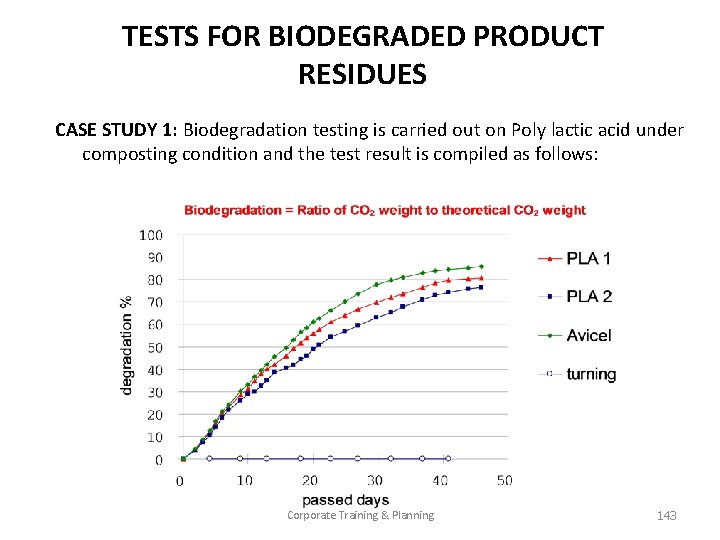
TESTS FOR BIODEGRADED PRODUCT RESIDUES CASE STUDY 1: Biodegradation testing is carried out on Poly lactic acid under composting condition and the test result is compiled as follows: Corporate Training & Planning 143

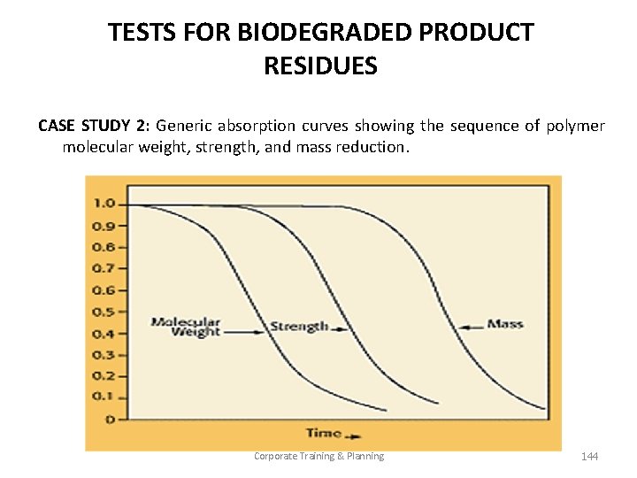
TESTS FOR BIODEGRADED PRODUCT RESIDUES CASE STUDY 2: Generic absorption curves showing the sequence of polymer molecular weight, strength, and mass reduction. Corporate Training & Planning 144

REFERENCES • Vishu shah, “Hand Book of Plastics Testing Technology” second edition, John Willy & Sons, 1998. • Related Indian & International Standard. • Handbook of plastics test methods, R. P. Brown, George Goodwin Publication • Testing and Evaluation of Plastics, A. B. Mathur, I. S. Bhardwaj, Allied Publication, New Delhi. • Allen. W. S and Baker, P. N, “Hand Book of Plastics Technology” Vol. 2, CBS Publishers, New Delhi, 2004. Corporate Training & Planning 145

 Pace theory
 Object permanence
 How does concurrent planning support permanence
 Do dogs have object permanence
 Wat is permanence
 3 types of weathering
 Three types of weathering
 Example of chemical weathering
 Physical weathering and chemical weathering venn diagram
 Associative property vs commutative property
 Doctrine of blending
 Chemical property definition
 Extensive properties and intensive properties
 Extensive property in thermodynamics
 Vẽ hình chiếu đứng bằng cạnh của vật thể
 Phản ứng thế ankan
 Quá trình desamine hóa có thể tạo ra
 Các môn thể thao bắt đầu bằng tiếng nhảy
 Sự nuôi và dạy con của hươu
 điện thế nghỉ
 Dạng đột biến một nhiễm là
 Biện pháp chống mỏi cơ
 Trời xanh đây là của chúng ta thể thơ
 Gấu đi như thế nào
 Thiếu nhi thế giới liên hoan
 Vẽ hình chiếu vuông góc của vật thể sau
 Các châu lục và đại dương trên thế giới
 Một số thể thơ truyền thống
 Thế nào là hệ số cao nhất
 Frameset trong html5
 Hệ hô hấp
 Tư thế ngồi viết
 Số nguyên là gì
 Hình ảnh bộ gõ cơ thể búng tay
 đặc điểm cơ thể của người tối cổ
 Mật thư anh em như thể tay chân
 Chụp tư thế worms-breton
 ưu thế lai là gì
 Thẻ vin
 Cái miệng nó xinh thế
 Các châu lục và đại dương trên thế giới
 Bổ thể
 Từ ngữ thể hiện lòng nhân hậu
 Diễn thế sinh thái là
 Tư thế ngồi viết
 V cc cc
 Thơ thất ngôn tứ tuyệt đường luật
 101012 bằng
 Chúa yêu trần thế
 Sự nuôi và dạy con của hươu
 đại từ thay thế
 Vẽ hình chiếu vuông góc của vật thể sau
 Công thức tính độ biến thiên đông lượng
 Tỉ lệ cơ thể trẻ em
 Thế nào là mạng điện lắp đặt kiểu nổi
 Lời thề hippocrates
 The rock
 Biological weathering animals
 Weathering erosion and deposition
 Deposition weathering definition
 Weathering non examples
 Erosion in piney woods
 Chapter 7 weathering erosion and soil
 Whats weathering
 Venn diagram of mechanical and chemical weathering
 How can a prairie dog cause physical weathering
 Ice weathering
 Unloading joints
 Weathering
 Mechanical weathering examples
 Chapter 14 weathering and erosion review answers
 Chemical weathering
 Spheroidal weathering
 Distinguish between weathering and erosion
 Weathering and erosion video
 Weathering vs erosion
 Effects of weathering
 Mechanical and chemical weathering venn diagram
 Mechanical weathering is more rapid in warm wet climates
 Identify three agents of mechanical weathering
 Oxidation weathering
 Mechanical weathering
 Whats the definition of weathering
 Geology.com
 Pathways of weathering
 Poryphory
 Weathering vs erosion
 Differentiate between chemical and physical weathering.
 Decomposition weathering
 What causes weathering
 Edwards plateau weathering
 Weathering and soil erosion
 Ice wedging
 Freeze thaw is an example of what type of weathering
 What affects rate of weathering
 Erosion and weathering
 Chapter 10 section 1 weathering
 Weathering
 Examples of mechanical weathering
 Venn diagram of chemical and mechanical weathering
 Weathering vs erosion vs deposition
 Weathering
 Wind erosion
 Sub aerial weathering
 G rocks
 How does weathering occur
 Expansion and contraction weathering
 Pedochemical weathering
 Weathering
 Weathering
 Type of weathering
 Weathering and erosion difference youtube video
 Salt wedging weathering
 Examples of chemical and mechanical weathering
 Mechanical and chemical weathering venn diagram
 Carbonation chemical weathering
 Weathering and erosion virtual field trip
 Feldspar hydrolysis
 Wietrzenie
 Mechanical and chemical weathering venn diagram
 Weathering by water
 Water abrasion
 Sub aerial weathering
 Mechanical weathering defintion
 Definiton of river
 Which type of weathering
 Types of weathering
 Physical weathering
 Weathering erosion
 Stages of soil development
 Weathering and erosion
 Soil formation begins with weathering of
 Fall
Fall How does ice affect weathering
 When did this happen
 Earth definition
 Hsess
Hsess Frost action
 Soil scavenger hunt
 Types of weathering
 Venn diagram of mechanical and chemical weathering
 Chemical weathering
 What is weathering in science
 Goldrich stability series
 Dust bowl 1930s
 Weathering
 Weathering and erosion agents


