Product Development Lead PDL Training Program Workshop PDL


![Example of a Pre-Environmental Test Flow Receiving Inspection/ Card Level Testing [561/461] C&DH Box Example of a Pre-Environmental Test Flow Receiving Inspection/ Card Level Testing [561/461] C&DH Box](https://slidetodoc.com/presentation_image_h2/67840409250a3273181bf596ca2526e9/image-85.jpg)


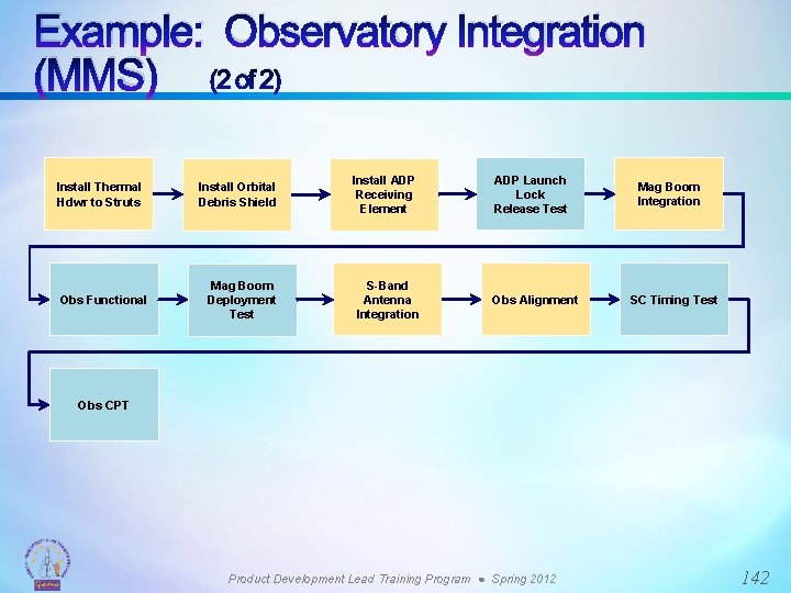
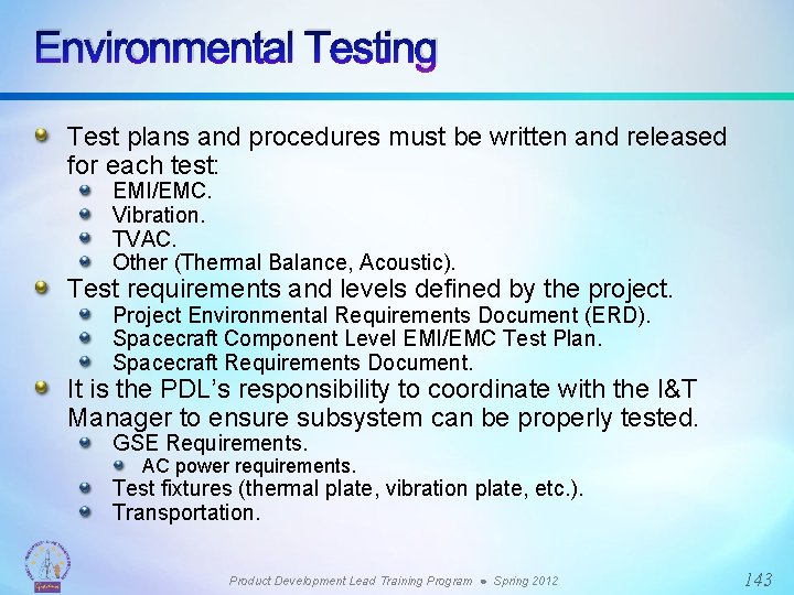
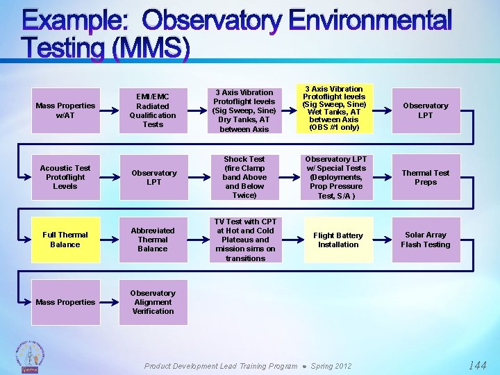
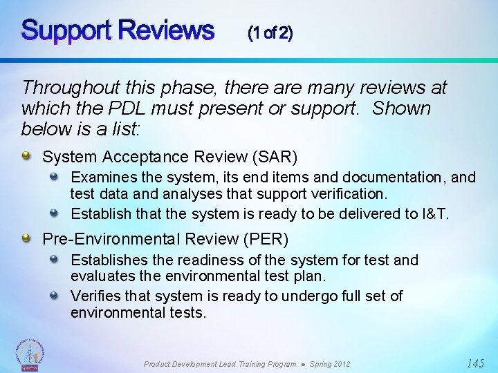
- Slides: 174

Product Development Lead (PDL) Training Program Workshop: PDL Role Throughout the Project Lifecycle Instructor: Craig Tooley (461) Session: PDL Training Program-1 ● Spring 2012 NASA Goddard Space Flight Center ● “Enabling the Reality of Tomorrow”

Workshop Goal and Learning Objectives Goal: To provide PDLs with an overview of their roles and responsibilities throughout each phase of the project lifecycle with an emphasis on proper planning. Learning Objectives: The PDLs will gain the knowledge required to properly plan for each phase of the project lifecycle. The PDLs will gain insight into the requirements imposed upon them by the customer regarding their deliverables. Product Development Lead Training Program ● Spring 2012 2

Message to PDLs Beyond what is outlined in this presentation, PDLs have other duties and they are as follows: Attending/organizing meetings (programmatic and technical) Planning/preparing for reviews (component level to box level) Organizing priorities and requests Leading team Preparing for ISO Audit Submitting New Technology Report (NTR) Product Development Lead Training Program ● Spring 2012 3

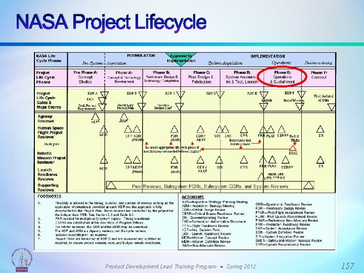
NASA Project/Mission Phases NASA organizes the execution of space flight projects into phases to enable management to track progress and to establish Key Decision Points (KDPs) at which the Agency commits to proceeding into, and funding, the next phase. KDPs are preceded by major external reviews which inform these decisions. NASA develops and executes missions on behalf of the Nation, with tax dollars. The goal of phased approach with KDPs is to prevent the expenditure of large amounts of money and effort in vain, i. e. determine things are not going well before it is too late to change course (KDPs are the events at which the decision authority determines the readiness of a program/project to progress to the next phase of the lifecycle (or to the next KDP). Product Development Lead Training Program ● Spring 2012 4

NASA Project/Mission Phases and the defining policies, responsibilities, and practices are extensively documented, the key resources include: NASA Space Flight Program and Project Management Requirements, NPR 7120. 5 (see NID 7120 -97) NASA System Engineering Handbook, NASA/SP-2007 -6105 The emphasis in this training is on the roles and responsibilities of NASA engineers, primarily Leads or PDLs, in each of the project phases, rather than the details of the management processes governing the progression thru the phases Product Development Lead Training Program ● Spring 2012 5

NASA Project/Mission Phases We’ll start here Product Development Lead Training Program ● Spring 2012 6

NASA Project/Mission Phases Key Decision Points Major Project Reviews precede each Key Decision Point and it is at KDP-C that NASA commits (Level 1 requirements, budget, schedule) for the mission FORMULATION IMPLEMENTATION A Pre-A Project Phases Key Decision Points Concept Studies B C D Concept & Preliminary Final Technology Design & Development Technology Fabrication Completion A B C E F System Operations & Closeout Assembly, Sustainment Test, & Launch D E F Mission Concept Review Systems Requirements Review Major Reviews Mission/System Definition Review Preliminary Design Review Critical Design Review Independent Cost Estimates Systems Integration Review Operational Readiness Review Flight Readiness Review Post Launch Assessment Review 8 Product Development Lead Training Program ● Spring 2012 7

NASA Project/Mission Phases Progression of Development Incremental Development Phases captured via baselines and bounded by Technical Reviews Phase A Phase B Phase C System Requirements Reviews System Definition Review Preliminary Design Review Phase D System Test Readiness Review Critical Design Review Phase E Post Launch Assessment Review Flight Readiness Review System Implementation System Requirements Definition Baselines Need System Design System Requirements Baseline Specify Preliminary Design Functional Baseline Detailed Design Allocated Baseline Decompose System Integration and Test System Installation and Acceptance Product Baseline Design Integrate Verify System Operations and Maintenance As Built Baseline Operational Baseline Operate Dispose 9 Product Development Lead Training Program ● Spring 2012 8

Technical Baseline Definitions (1 of 2) System Requirements Baseline (Phase A) The system requirements baseline is the approved system level functional and performance requirements. Established at the System Requirements Review (SRR). Functional Baseline (Phase A) The functional baseline is the approved documentation describing a system’s functional, performance, and interface requirements and the verifications required to demonstrate achievement of those specified characteristics. Established at the System Definition Review (SDR). Allocated Baseline a. k. a. the ‘Design-to’ Baseline (Phase B) The allocated baseline extends the top-level performance requirements of the functional baseline to sufficient detail for initiating manufacturing or coding. Established at the Preliminary Design Review (PDR). Product Development Lead Training Program ● Spring 2012 9

Technical Baseline Definitions (2 of 2) Product Baseline a. k. a. the ‘Build-to’ Baseline (Phase C) The product baseline describes detailed form, fit, and function characteristics; the selected functional characteristics designated for production acceptance testing; the production acceptance test requirements. Established at the Critical Design Review (CDR). ‘As-Built’ Baseline (Phase D) The as-built baseline describes the detailed form, fit, and function of the system as it was built. Established at the Flight Readiness Review (FRR). Operational Baseline a. k. a. ‘As-Deployed’ Baseline (Phase E) The as-deployed baseline occurs at the Operational Readiness Review (ORR). At this point, the design is considered to be functional and ready for flight. All changes will have been incorporated into the final documentation. Product Development Lead Training Program ● Spring 2012 10

The Engineering Activities in the Project Lifecycle Mission Requirements & Priorities Develop System Requirements & System Architecture Allocate Performance Specs & Build Verification Plan n& e itio nc os ue mp eq co n S De nitio fi De B Design Components Integrate System & Verify Performance Specs Component Integration & Verification Verify Component Performance Fabricate, Assemble, Code & Procure Parts C E D System Level Subsystems Ve In rifi teg ca ra tio n. S n& eq ue nc e A System Demonstration & Validation Components Time and Project Maturity Product Development Lead Training Program ● Spring 2012 11

The Progression of Requirements Lifecycle Relationships Phase B Phase A Concept Studies Concept & Technology Development Preliminary Design & Tech Completion Phase C Phase D Final Design & Fabrication System Assembly , Int & Test, Launch Phase E Operations & Sustainment Organizations & People Artifacts Problems Concepts Expectations CONOPS System Reqmts. Validation Plan Prelim. Design Subsystem Reqmts. Verification Plan Design-to Specs As-built Build-to Specs Verification Procedures Product Development Lead Training Program ● Spring 2012 As-verified Asdeployed Asoperated Anomalies 12

NASA Time Scales for Project Lifecycle (1 of 2) For a NASA Announcement of Opportunity (AO)-driven mission: The proposing team works Pre-Phase A in 1 st round and Phase A in 2 nd round (if they win). Lots of internal research and development (IRAD) dollars here. Official acceptance puts the mission/proposer into Phase B. Still has to go through confirmation review to enter Phase C. Product Development Lead Training Program ● Spring 2012 13

NASA Time Scales for Project Lifecycle (2 of 2) AO Mission Types Mission Class Level of Acceptable Risk Discovery Program example: A Minimum Risk Phase A Concept Study – 7 months B Risk/Cost Compromise Selection through launch ~ 7 years Mars Scout Program example: Single Purpose, Repeat Mission Possible, Some C Phase A Concept Study – 9 months Risk Allowed Selection through launch ~ 6 years Routine, Rapid Mission, or Proof of Concept, D Small Explorer Program example: More Risk Allowed Phase A Concept Study – 3 months Selection through launch ~ 3 -4 years For a facility-class telescope development, 10 -15 years depending on technology development required. For a human spacecraft development (Pre-phase A through Phase D/Launch), on the order of 10 -20+ years. Product Development Lead Training Program ● Spring 2012 14

Formulation – Pre-Phase A Formulation Pre-Phase A (Concept Studies) Purpose: To produce a broad spectrum of ideas and alternatives for missions from which new projects can be selected. Define the mission needs, goals and objectives. Perform studies of a broad range of mission concepts that contribute to goals and objectives. Develop draft project-level requirements, operations concept, and potential technology needs. Show that at least one mission concept can work. => Complete Mission Concept Review (MCR): review overall approaches as a baseline for Phase A. Product Development Lead Training Program ● Spring 2012 15

Formulation – Phase A Formulation Phase A (Concept & Technology Development) Purpose: To determine the feasibility of a suggested new system in preparation for seeking funding. Define mission success, and minimum mission. Perform trade studies to compare mission concept options. Develop a baseline mission concept, including best technical approach, project execution, cost and schedule. Complete the requirements to the subsystem level. Identify requirements flow between and across subsystems. Begin needed technology developments. => Complete System Requirements Review (SRR): Review requirements as baseline for final concept. Establishes the System Requirements baseline. => Complete System Definition Review (SDR/MDR): Review baseline for Phase B. Establishes the Functional baseline. Product Development Lead Training Program ● Spring 2012 16

GSFC Integrated Design Center The principal formal resource the Center uses for collaborative conceptual design activities is the Integrated Design Center (IDC). The Center has two dedicated facilities where design teams and customers collaborate in an environment that promotes rapid development and efficient trade studies of space system architectures, applications and concepts. The Mission Design Lab (MDL) offers conceptual end-to-end mission design and analysis while the Instrument Design Lab (IDL) offers conceptual design and analysis of instrument systems. Formulation Teams use the IDC to develop conceptual designs that are then worked and matured during formulation phases. Other methodologies are also used that are less structured than the IDC in which the engineering teams works in a tiger team or Skunkworks mode to develop conceptual designs. Product Development Lead Training Program ● Spring 2012 17

PDL Role in Formulation Phases (1 of 2) PDL is part of the engineering team charged with first answering the question “can it be done? ”, progressing to “what is the best baseline technical approach that should be pursued? ” and finally culminating in “what are the requirements necessary to commence with Preliminary Design of the conceptual baseline? ” Key aspects of the work: Aspects of the mission that do not push the boundaries of technology (high Technology Readiness Level (TRL) areas) are engineered based on historic analogies and parametric trades. The developmental aspects (lower TRL levels) of a potential mission are characterized by research and more detailed trade/feasibility studies. Product Development Lead Training Program ● Spring 2012 18

PDL Role in Formulation Phases (2 of 2) The Team’s Product consists of: A system architecture that is evolved from straw-man to a conceptual baseline. Expressed as box level block diagram with characteristics for each box/block. Level 1 -Level 3 requirements established by the time Phase A is complete. Technical resource estimates (mass, power, bandwidth, CPU capability, etc. ). An analogy/parametrics-based cost estimate. An understanding of the major risks, i. e. , the tall-poles and challenges. Product Development Lead Training Program ● Spring 2012 19

PDL Role in Formulation – Key Advice (1 of 3) The objective of this phase is establishing feasibility for decisional purposes and then a baseline from which to go forward with planning the development For aspects of the mission that are not technological challenges, the key focus is on scoping the technical resources and the cost. A detailed level of design is not required but design concepts drawn from experience (parametric and analogy based) are prone to being judged simpler and cheaper than what the real world will actually yield so always keep this in mind. Product Development Lead Training Program ● Spring 2012 20

PDL Role in Formulation – Key Advice (2 of 3) For technological developments sufficient design, analysis, and research must be done to establish “proof-of-concept” and develop a “ball-park” estimate of the technical resources and cost. Confidence in the boundaries of the estimates needs to be high as go-forward decisions will be based on them. Avoid overconfidence that “we’ll figure it out” when we get into the details. Technology Readiness Level (TRL) – Provides a scale against which to measure the maturity of a technology. TRLs range from 1, Basic Technology Research, to 9, Systems Test, Launch, and Operations. Typically, a TRL of 6 (i. e. , technology demonstrated in a relevant environment) is required for a technology to be integrated into the mission. Product Development Lead Training Program ● Spring 2012 21

PDL Role in Formulation – Key Advice (2 of 3) There will often be pressure to “keep it in the box” from a cost and schedule standpoint and design-to -cost is a valid request. But, you must be able to stand behind your results. So, be prepared to withstand some pressure to simply lower the estimates to “make it fit”. Product Development Lead Training Program ● Spring 2012 22

Examples of Formulation Work at GSFC (1 of 2) MMS – The mission concept was developed in the GSFC MDL and a significant number of the current PDLs (MMS is in Phase C now) were involved beginning with the MDL conceptual design. The MMS SRR package is available as a reference and example of the culmination of mission/spacecraft Phase A work. LRO – The LRO mission was on a accelerated schedule with a combined Phase A/B and not pre-Phase-A. The Phase work was done by the assigned PDL in a “skunkworks” type mode and proceeded directly into development. The LRO SRR package is available as a reference and example of the culmination of mission/spacecraft Phase A work. Product Development Lead Training Program ● Spring 2012 23

Examples of Formulation Work at GSFC (2 of 2) Exploration Flagships Flight Servicing Vehicle (FSV) – This was a pre-Phase A/Phase A assignment GSFC took for HQ to examine the feasibility of an element of a potential new program. It is a good example of PDL work on a mission which was clearly for NASA decisional purposes and known from the onset to not be a forthcoming GSFC project. The MDL report on the effort is available as a reference and example of work supporting program definition. ICESat-2/ATLAS Instrument – Phase development was initiated in the GSFC IDL and the mission and instrument have moved on into Phase B. The i. SRR/i. SDR package is a good example of Phase A instrument development work and is available as a reference. Product Development Lead Training Program ● Spring 2012 24

Reference and Tutorial Resources NASA Space Systems Engineering Website: http: //spacese. spacegrant. org Excellent source for NASA engineers, the source for some of the content of this module NASA Chief Engineer's Office: http: //oce. nasa. gov/oce/home/index. html NASA Academy of Program/Project & Engineering Leadership (APPEL) - Case Studies: http: //www. nasa. gov/offices/oce/appel/knowledge/publications/32. html Goddard Systems Engineering Seminar Series: http: //ses. gsfc. nasa. gov/ GSFC Integrated Design Center: http: //idconline. gsfc. nasa. gov/idc/ Goddard Directives Management System: http: //gdms. gsfc. nasa. gov/gdmsnew/home. jsp MMS SRR Briefing Package: https: //aetdwiki. gsfc. nasa. gov LRO SRR Briefing Package: https: //aetdwiki. gsfc. nasa. gov Exploration Flagships Flight Servicing Vehicle (FSV) MDL Final Report: https: //aetdwiki. gsfc. nasa. gov ICESat-2/ATLAS Instrument SRR/SDR (i. SRR/i. SDR) Briefing Package: https: //aetdwiki. gsfc. nasa. gov Product Development Lead Training Program ● Spring 2012 25

PHASE B Team Members: Dave Content/551, Kenny Harris/543, Bill Yuknis/561 26

Agenda (1 of 2) Knowledge of Configuration Management/Risk Management Maintain Communication Channels with Stakeholders and Customers Identify Staffing Needs Identify Launch Vehicle Requirements and Constraints Develop Safety Plan (Hardware and Personnel) Develop Trade Studies Define Subsystem Requirements Allocate Requirements to Components Product Development Lead Training Program ● Spring 2012 27

Agenda (2 of 2) Identify Verification Approach Develop Verification Matrix Generate Top-Level Design Partition Design into Work Packages Design the Subsystem Analyze Subsystem Performance Generate RFIs and RFPs Start Long Lead Procurements Conduct Subsystem Lifecycle Reviews Develop Schedule and Cost Estimates Product Development Lead Training Program ● Spring 2012 28

NASA Project Lifecycle Product Development Lead Training Program ● Spring 2012 29

Phase B Definition Phase B Preliminary Design and Technology Competition. Purpose To define the project in enough detail to establish an initial baseline capable of meeting mission needs. Product Development Lead Training Program ● Spring 2012 30

Configuration Management (1 of 2) Every project must establish a configuration management system (as NID 7120 -97). Configuration Management (CM) is the process of storing and managing documentation associated with a project. Examples include: Interface Control Documents Schematics Drawings End-Item-Data Packages Reviews Analyses Flight Software Code (typically uses their own internal CM) Flight Software Test Procedures Product Development Lead Training Program ● Spring 2012 31

Configuration Management (2 of 2) The PDL needs to work with the project to establish Configuration Change Boards (CCBs) that are responsible for reviewing and approving documentation. The PDL must ensure that all team members generate and submit documentation to CM for release. Work cannot proceed without documentation being formally released for flight products and, depending on the project, ETUs as well. Product Development Lead Training Program ● Spring 2012 32

Risk Management Risk management is required by NPG 7120 (NID 712097), see also NPR 8000. 4, Risk Management is a process in which the PDL must identify elements of risk and pass them up to the project for monitoring. Risks must be monitored at the project level with respect to their impact and likelihood. The PDL is responsible for identifying risks to the schedule or design and devising contingency plans to mitigate the risk. Risk correlates with cost. Risk management continues throughout the project lifecycle. Product Development Lead Training Program ● Spring 2012 33

Maintain Communication with Stakeholders One of the most important things that a PDL can do is to maintain clear, consistent, and effective communication with the stakeholders throughout the entire project lifecycle. Stakeholders include: Stakeholders (dealt with often) Stakeholders (dealt with infrequently) Project Senior Management NASA Center Management Systems Engineering Collaborating Partners Directorate/Division/Branch Management Facilities Team Members Launch Site Personnel Procurement Mission Operations Personnel Product Development Lead Training Program ● Spring 2012 34

Identify Staffing Needs (1 of 2) Typically, Phase A identifies major elements for a subsystem but more specific staffing needs need to be identified down to the component level – individual roles and tasks. Identify all roles and tasks for the remaining phases, not just B. Identify individuals by name. Identify type of staffing (Civil Servant or Contractor). Example staffing profile Product Development Lead Training Program ● Spring 2012 35

Identify Staffing Needs (2 of 2) Devise a staffing profile in terms of fractional Full-Time Equivalents (FTEs) (or Work-Year Equivalents (WYE)). Can be broken down by month or by quarter (work with the project to determine how to best fill their needs). It is important that you get approval from your branch management before submitting your staffing needs to the project. Once you receive project authorization, work with your branch to assign staff. A key document and deliverable item is the staffing profile organized by roles and phasing. Product Development Lead Training Program ● Spring 2012 36

Identify LV Requirements and Constraints The selection of a launch vehicle has a tremendous impact on the resulting design and approach. Available Volume for the payload. Launch environment. Mass allocations. Electrical and mechanical interfaces. Choice of propulsion and handling processes. EMI/EMC considerations (communications, electrical subsystems). Contamination handling. Thermal management (i. e. , pre-launch activities). Key documents are the interface control documents. Electrical. Mechanical. Propulsion. Product Development Lead Training Program ● Spring 2012 37

Develop Safety Plans for Hardware and Personnel are required as per 500 -PG-8715. 1. 2 B. Safety plans address that hardware is not damaged or that personnel is not injured during the course of assembling and testing hardware. Key manufacturing processes may require additional safety plans. Safety plans include, where applicable [go to the PDL Wiki website for latest forms]: Lift Operations Electrostatic Discharge Training High Voltage Training Operation of Pressure Vessels Cryogenic Electromagnetic Radiation Nuclear Radiation Hazard Analysis Some PDLs are required to write a Safety Plan. Product Development Lead Training Program ● Spring 2012 38

Develop Trade Studies During this early stage, decisions may need to be made to select one approach over another, examples include: Network Topology Printed Wiring Board Material Processors Flight Software Trade Studies [e. g. , Operating Systems] Material for Structural Components Fabrication and Testing Approaches Includes Make/Buy decisions. All ongoing trades should be resolved by no later than CDR. Product Development Lead Training Program ● Spring 2012 39

Define Subsystem Requirements Project requirements flow down and frequently need to be derived into lower level requirements to your specific subsystem. This requires effective communication with the project and interface elements. The following are examples of a Level 3 and Level 4 requirements for a C&DH subsystem with identifying links to parent requirements. CDH, Level 3 CDH S-Comm, Level 4 Product Development Lead Training Program ● Spring 2012 40

Identify Verification Approach All requirements must be verified and traceable to specific test documents. In order to facilitate this, an approach needs to be identified (e. g. , a using spreadsheet). In addition to a spreadsheet, individual requirements need to be called out and determined how it will be verified such as by analysis, inspection, test, or demonstration. Software tools such as DOORS or MKS are often used here. Flight Software development includes generation of a Verification Test Plan. Product Development Lead Training Program ● Spring 2012 41

Develop Verification Matrix The verification matrix identifies means by which each requirement is verified. Methods include test, analysis, inspection, demonstration. Helps assign responsibility for verification. Helps ensure all requirements are verified. A simplified example of a verification matrix is shown below: Verification Stage Para # Requirement Statement Development 6. 2 Vehicle design factors and reliability included Analysis 3. 2 High reliability parts used Component Analysis 3. 3. 1. 1. 3 Can discharge electrical potential Analysis Qualification Acceptance Record View Pre. Launch Flight/ Operational Postflight/ Disposal Test Data taken from NASA Systems Engineering Handbook, Appendix b-9. Product Development Lead Training Program ● Spring 2012 42

Partition Design into Work Packages Any complex engineering problem can be partitioned into smaller problems – always remember this rule of thumb. It’s one of the best tools for not being overwhelmed by large or complex problems. Partitioning is the process of breaking down a complex system into groups of simpler systems. These simpler systems are usually easier to manage from a task and resource standpoint. Example: Break down an electronics box into structure and individual card level, or break down an instrument into components and structure. Product Development Lead Training Program ● Spring 2012 43

Design the Subsystem (1 of 2) Mission, science, and vehicle requirements are gathered. Overall design becomes more concrete in terms of specific interfaces (electrical, mechanical, thermal). The layout and form factor become defined. Detailed designs are driven by communication, alignment, field of views, and propulsion considerations. Schematics and assembly drawings are produced. Progress from system level – subsystems, components, etc. Example: Power Control Box Pre-Phase A – Power Control Box Phase A – Block Diagram to card level: high and low voltage cards, power management, etc. Phase B – Design cards, layout box structure and interfaces Phase C – Detailed requirements, parts identification, detailed design, procurement plan, etc. Product Development Lead Training Program ● Spring 2012 44

Design the Subsystem (2 of 2) Consider the long view with respect to integration, testing, shipping and handling. For Mechanical Systems: Ensure that analysis and tests performed confirm that the design meets the requirements. Analyze performance over range of likely conditions (e. g. , temperature range, voltage range, radiation environment, likely variation range of material properties, etc. ). Product Development Lead Training Program ● Spring 2012 45

Pre-Procurement: Generate RFIs and RFPs Procurement lead times are long. Procurement has a table of procurement time needed vs. dollar value. Can be up to a year, depending on size. Identify (preferably multiple) potential sources early. RFI is Request For Information. Is a non-binding way to generate information to help develop procurement specifications and lists of sources. RFP is Request for Proposal. Initial procurement activity. Product Development Lead Training Program ● Spring 2012 46

Start Long Lead Procurements Identify long lead procurements. Estimate dollar value and time needed early in Phase B. Work with project planner to understand relationship of these procurements to the subsystem and system schedule critical path. This helps prioritize the procurements. Procurement will need at least the following info: Dollar value, delivery time, and phasing of money needed. Statement of Work (SOW). List of potential sources. If only one source is available, a justification is needed for other than competitive procurement. Specifications. Identify any eligible small businesses or set-aside companies. Product Development Lead Training Program ● Spring 2012 47

Subsystem Lifecycle Reviews For Phase B, PDLs are responsible for the following review: Preliminary Design Review (PDR). Prior to PDR, PDLs are responsible for various peer reviews such as: Documentation Review Interface Control Document (ICD) Requirements Document Specification Document Component Design Review (e. g. Single Board Computer Design Review) Code Walk Through (e. g. FPGA VHDL Code Walk Through) Product Development Lead Training Program ● Spring 2012 48

PDL State of Mind Product Development Lead Training Program ● Spring 2012 49

PDR (1 of 16) The purpose of the PDR is to demonstrate project readiness to proceed with the detailed design and to complete the flight and ground system development and mission operations in order to meet mission performance requirements within the identified cost and schedule constraints. To that end, the project demonstrates that the preliminary design meets all system requirements with acceptable risk. It shows that the correct design option has been selected, resource allocations have been made, interfaces have been identified, and verification methods have been identified. Supportive design analyses confirm compliance with requirements (GSFC-STD-1001). Product Development Lead Training Program ● Spring 2012 50

PDR (2 of 16) Criteria: Design Description (including Requirements, Evolution and Heritage): A complete and comprehensive definition of the entire design exists to the component level Current status of compliance with the Goddard Rules (GSFCSTD-1000) reflects adequate progress of activities to date and satisfactory plans for future activities. Any required waivers/deviations have been approved. Results of trade studies and rationale for selected alternatives are defined. Remaining trade studies are identified and potential impacts are understood. Product Development Lead Training Program ● Spring 2012 51

PDR (3 of 16) Requirements flowdown and traceability to the appropriate subsystem of each system element, and, to the extent practical, to the component, has been completed. A preliminary verification matrix has been defined that includes the selected verification method for each requirement, including the compatibility of units of measurement, where applicable. Requirements and design changes since MDR and SDR and their rationale are documented. Appropriate descopes have been identified: Plans and trigger points have been identified. Impact to science objectives and deliverables has been defined. Potential impacts to mass, power, software and other resources have been quantified. Budget and schedule impacts have been estimated. Product Development Lead Training Program ● Spring 2012 52

PDR (4 of 16) Long lead items and their acquisition plans have been identified. Any fabrication needed prior to CDR has been identified. Proof of heritage applicability (similarity) has been assessed. Required analyses and/or tests of heritage designs to address all design modifications, changes in the expected environment and operational differences has been identified. EEE Parts Considerations: Parts Stress Analysis (PSA) requirements have been defined. Radiation tolerance requirements have been defined. Selection, de-rating, screening and qualification test criteria are defined. Preliminary parts lists are complete. Long lead acquisitions are planned. Risk mitigations are defined. Product Development Lead Training Program ● Spring 2012 53

PDR (5 of 16) Software Considerations: Preliminary requirements are identified, including language, structure, logic flow, CPU throughput and memory loading, re-use, safety, and security. Nominal operating scenarios are identified, along with fault detection, isolation, and recovery strategies. Design and development plans are defined including lines of code estimates, number of builds, tools, and procedures. Verification strategies are defined including test environments. Preliminary system performance estimates exist. IV&V plans are identified. Product Development Lead Training Program ● Spring 2012 54

PDR (6 of 16) Total System Performance (budgets/projections/margins for combined optical, thermal, mechanical, control, etc. ): Budgets and margins for system performance (pointing, throughput, etc. ) are defined. Preliminary system performance estimates are complete. Estimates of critical resource margins (i. e. , mass, power, delta V, CPU throughput and memory, etc. ) have been delineated based on design maturity. Sufficient margin exists based on applicable standards. Risk mitigation strategies are defined for margins below guidelines. Preliminary analyses are completed for: Mechanical loads, stress, fracture control, and torque margins. Thermal environment, including predicted performance and margins. Product Development Lead Training Program ● Spring 2012 55

PDR (7 of 16) Radiation protection requirements and design margins. Expected lifetime and margins for limited life items. Design Analyses: Preliminary analyses critical to proof of design are complete. Analyses required to enable detailed design should be complete. Rationale and risk assessment exists for outstanding analyses that may, at completion, impact the design baseline, i. e. , mass, power, volume, interfaces. Status and schedule of final analyses are defined. Development Test Activities: Breadboard and engineering model development activities have been defined. Test objectives and criteria have been identified. Product Development Lead Training Program ● Spring 2012 56

PDR (8 of 16) Completed breadboard and engineering model test results have been iterated into the design. Required life tests have been identified and are planned for completion by CDR. Risk Management: A risk management process that meets GPR requirements is defined and utilized. All significant risks, problems, and open items are identified and tracked (including programmatic, development and flight performance related items). Risk mitigation plans are appropriate and credible. Lessons learned have been appropriately researched and adapted. Product Development Lead Training Program ● Spring 2012 57

PDR (9 of 16) Initial reliability analyses are completed and results have been factored into the design. Analyses include: Fault Tree Analysis (FTA). Probabilistic Risk Assessment (PRA), as appropriate. Failure Mode and Effects Analysis (FMEA). Single Point Failure (SPF) assessment and retention rationale. Reliability driver (weak design links) assessment. Worst Case Analysis (WCA). Safety: An approved safety plan identifies all requirements as well as any planned tailoring approaches or intended non-compliances. Preliminary hazards, controls, and verification methods are identified and documented. Any open safety issues are identified with plans for resolution. Plans and schedules for all required safety submittals are defined and documented. Product Development Lead Training Program ● Spring 2012 58

PDR (10 of 16) Assurance Activities: Quality Assurance plans are complete including the problem reporting system. Preliminary production planning and process controls (including strategy for control/verification of units of measurement) have been identified. Applicable workmanship standards have been defined. Special materials considerations have been identified. Implementation Plans: Equipment and facilities for the development and test of hardware and software have been identified. Preliminary planning for Systems Integration and Test activities, including science validation and calibration, as well as operations compatibility testing, has been defined. Facilities are available and, if needed, utilization agreements are in work. Product Development Lead Training Program ● Spring 2012 59

PDR (11 of 16) Risks associated with I&T have been characterized and preliminary mitigations have been defined. Contamination requirements and preliminary control plans are defined. Interface Control Documents: Preliminary ICDs, with external systems as well as between system elements, are complete. “TBD”s are clearly identified. Plans and schedules exist for their definition. Qualification/Environmental Test Plans and Test Flow: Approach to Qualification/Proto- flight/Acceptance testing has been defined. Environmental verification flow is traceable from component to system level. Product Development Lead Training Program ● Spring 2012 60

PDR (12 of 16) Interleaving of environmental and functional test flow has been defined. Preliminary identification of all mechanical and electrical GSE has been completed. Special test requirements have been defined. Test facilities have been defined. Facilities are available and, if needed, utilization agreements are in work. Logistics: Transportation methods are identified including environmental control and monitoring considerations. Preliminary identification of all GSE has been completed. Transportation container requirements have been identified. Product Development Lead Training Program ● Spring 2012 61

PDR (13 of 16) Launch Vehicle Interfaces: Preliminary ICD is complete. “TBD”s are clearly identified. Plans and schedules exist for their definition. Payload-driven first flight/mission unique items have been identified and mission implications are understood. Potential launch vehicle related risk items are identified. Preliminary vehicle Orbital Debris Assessment has been completed. Preliminary integrated payload/launch vehicle activity flow has been defined. Preliminary schedule of all vehicle/payload inter-related activities has been defined. Preliminary coupled loads analysis has been initiated. Product Development Lead Training Program ● Spring 2012 62

PDR (14 of 16) Ground Operations, Mission Operations, End-of- Life: Science and mission operations concepts are defined. Launch site and mission operations unique ground systems have been defined. Preliminary plans are defined for launch site activities, launch and early orbit operations. Preliminary planning for involvement and training of launch site and of mission operations teams are defined. Preliminary Orbital Debris Assessment is complete. Potential trades have been determined. End-of-life requirements and design accommodations are understood. Programmatics: Organization and staffing plans delineate clear responsibilities and adequate assignment of current and future staff. Product Development Lead Training Program ● Spring 2012 63

PDR (15 of 16) Appropriate processes and metrics are in place to track and control cost, schedule, and technical activities throughout the remaining life-cycle. Appropriately detailed schedules show realistic event times as well as appropriate funded slack and are compatible with approved launch dates. Cost to complete shows adequate spending profiles and financial reserves, and is compatible with allocations. Project and Independent Review Activity: Timely response to RFAs from previous IIRT reviews has occurred. Resultant actions have been implemented effectively. Schedule for completion of any outstanding RFAs is defined. Product Development Lead Training Program ● Spring 2012 64

PDR (16 of 16) An appropriate set of engineering peer reviews has been conducted and documented in compliance with GPR requirements. Resultant actions have been effectively dispositioned and executed. Appropriate additional reviews are planned. Recommendations from other project or external review activity that is applicable to the subject matter of the PDR have been adequately implemented. Product Development Lead Training Program ● Spring 2012 65

Update Schedule and Cost Estimates Labor (Civil Servants and Contractors) Procurement Travel Training EEE and Mechanical Parts Fabrication and Assembly Equipment Laboratory Maintenance Environmental Test Facilities Product Development Lead Training Program ● Spring 2012 66

PHASE C Team Members: Dave Raphael/561, Mark Walters/582 67

Agenda Knowledge of Problem Reporting Process Maintain Communication Channels with Stakeholders and Customers Establish a Team Finalize Verification Matrix Build Subsystem Components Build GSE/Test Tools Test GSE/Test Tools Certify GSE Test Subsystem Components Integrate Subsystem Components Perform Interface Test Conduct Subsystem Lifecycle Reviews Develop Schedule and Cost Estimates Product Development Lead Training Program ● Spring 2012 68

NASA Project Lifecycle Product Development Lead Training Program ● Spring 2012 69

Phase C Definition Phase C Final Design, Fabrication and Test. Purpose To complete the detailed design of the system (and its associated subsystems, including its operations systems), fabricate hardware, code software, and test the system. Product Development Lead Training Program ● Spring 2012 70

Stakeholders and Customers Stakeholder: n. 1. a person or group owning a significant percentage of a company’s shares 2. a person or group not owning shares in an enterprise but affected by or having an interest in its operations, such as the employees, customers, local community, etc. Branch, Division, and Directorate Management Customer: n. One that buys goods and services Project Management It is imperative for a PDL to maintain communications with the stakeholders and customers especially during Phase C since the goal is to finalize the design, fabricate and test the hardware. Missing or not implementing requirements into the final design can be costly and generate a major schedule slip. Product Development Lead Training Program ● Spring 2012 71

Team Organization PDLs need to be proactive and assertive when establishing their team, i. e. , staffing needs should have been identified in the previous phase (Phase B) and be in place by the time Phase C starts. The goal is to make certain that all engineers and technicians (civil servants and/or contractors) and all tasks are in place since there always concurrent projects/R&D undertakings competing for the same manpower, thus the need to be proactive and aggressive beforehand. Product Development Lead Training Program ● Spring 2012 72

Example of a Team Organization C&DH PDL Dave Raphael/561 System Engineering EEE Parts Antonio Reyes/MEI C&DH Deputy PDL Noosha Haghani/561 Radiation Mike Xapsos/561 Reliability Thiago Pires/SRS Space. Wire Chris Dailey/QSS Processor Card Lead Engineer Robert Stone/561 Communication Card Lead Engineer Damaris Guevara/561 FPGA Engineer Locksley Haynes/MEI Verification Engineer Omar Haddad/QSS Diagnostics Engineer Victor Bigio/582 Analog Card Lead Engineer Alex Kisin/MEI FPGA Engineer(s) Damaris Guevara/561 Tom Winkert/587 Verification Engineer(s) Noosha Haghani/561 Shahana Pagen/MEI Backplane Lead Engineer James Fraction/561 Mechanical Lead Engineer Milton Davis/596 Manufacturing Lead Engineer(s) Dave Raphael/561 Cindi Lewis/MEI I&T Lead Engineer(s) Dave Raphael/561 Noosha Haghani/561 Cindi Lewis/MEI FPGA Engineer Brian Smith/Stargazer Mechanical Design Matt Colvin/OSC Signal Integrity Analysis Dennis Albaijes/561 Verification Engineer(s) James Fraction/561 Victor Bigio/582 Structural Analysis Eric Gorman/596 PWB Layout NG Thermal Analysis Matt Colvin/OSC PWB Fabrication NG PWB Assembly Aeroflex, NG Product Development Lead Training Program ● Spring 2012 73

Verification Matrix (1 of 2) Verification proves that a realized product for any system model within the system structure conforms to the “build-to” requirements (for software elements) or “realize-to” specifications and design descriptive documents (for hardware elements, manual procedures, or composite products of hardware, software, and manual procedures). Types of Verification: Analysis: The use of mathematical modeling and analytical techniques to predict the correctness of a design. Demonstration: Showing that the use of an end product achieves the individual specified requirement. Inspection: The visual examination of a realized end product (typically used to verify physical design features). Test: The use of an end product to obtain detailed data needed to verify performance, or provide sufficient information to verify performance through further analysis. Product Development Lead Training Program ● Spring 2012 74

Verification Matrix (2 of 2) When finalizing the Verification Matrix, it is highly recommended to meet with Systems Engineering (it will most likely be several meetings) and ensure that they are onboard with the method, strategy, etc. chosen to verify each requirement. It is also imperative to keep the Verification Matrix up-to-date. Please do not wait until the end of environmental testing and/or Spacecraft I&T to accomplish this task as certain details may be missed and/or forgotten. Product Development Lead Training Program ● Spring 2012 75

Example of a Verification Matrix RUI Req. Section # Req. Title Verification Method Verification Tier RCDH_0267 4. 1. 5. 6 SRAM Capacity Inspection Component RCDH_0251 4. 1. 6 Test Subsystem RCDH_0083 4. 1. 7. 1 Health and Status Telemetry Data Storage Volume Inspection Component RCDH_0084 4. 1. 7. 2 Data Storage EDAC Analysis Component RCDH_0085 4. 1. 7. 3 Data Storage Memory Scrubbing Test Component RCDH_0108 4. 2. 1 Mass Allocation Test Subsystem RCDH_0109 4. 2. 2 Nominal Power Allocation Test Subsystem RCDH_0282 4. 3. 1. 1 Operating Voltage Range Test Component Subsystem RCDH_0993 4. 3. 1. 2 Spacecraft Survival Critical Test Voltage Component Subsystem RCDH_0283 4. 3. 1. 3 Abnormal Voltage Component Inspection V. Strategy V. Planning I: Processor Card Specification T: Box ATP 461 -CDH-SPEC-0011, Section 3. 5. 3 461 -CDH-PROC-0015, Section 4. 30/32/5. 30/32 I: Processor Card 461 -CDH-SPEC-0011, Section Specification 3. 5. 4 I: EEE PCB Approval Verified by part data sheet for (PIMS Report) the SRAM 461 -CDH-LIST-0022 T: Processor Card SDRAM is scrubbed via 461 ATP CDH-PROC-0008, Section 10. 4. 17 T: Electrical Integration 461 -CDH-PROC-0013, Section 5. C&DH box also will be weighed before integration to the spacecraft deck (probably by the MECH group) T: Electrical Integration 461 -CDH-PROC-0013, Section TBD T: Thermal Vacuum 461 -CDH-PROC-0019 tests this Test at high and low Voltages at hot and cold plateaus LVPS schematic shows that the three DC-DC converters part #s (S 2803 R 3 S, LS 2803 R 3 S, SMSA 2812 D-00). They are rated for 0 -40 Volts, drawing #2148500. Parts list CCB is 461 -CDH-LIST-0051 Product Development Lead Training Program ● Spring 2012 76

Subsystem Components Whether subsystem components are being developed in-house or procured, PDLs need to make certain that all the necessary reviews take place and all documentation are approved/released prior to building hardware. Once the design is achieved, it is imperative to hold a peer review for each component (card design, FPGA design, chassis design, etc. ) to ensure not only all requirements are met, but also that proper design techniques are being followed. Proper and thorough reviews will help prevent issues in the long run. Product Development Lead Training Program ● Spring 2012 77

Example of a Board Assembly Process Board Design PWB Layout (Component Placement) PWB Component Placement Review PWB Layout (Routing) Signal Integrity Analysis PWB Routing Review PWB Drawing Formulation PWB Drawing Review PWB Bare Board Procurement PWB Assembly Drawing Formulation PWB Assembly Drawing Review Work Instructions Formulation PWB Coupon Analysis Manufacturing Readiness Review Board Assembly GSFC Contractor GSFC & Contractor Product Development Lead Training Program ● Spring 2012 78

GSE During the course of a project, most ACS components, instruments, etc. by and large don’t show up until spacecraft I&T. Therefore, it is vital for PDLs to ensure all requirements/interfaces can be tested effectively using a GSE. It may be a surprise to some that a high percentage of issues discovered during troubleshooting of hardware is attributed to GSE failures. GSE typically doesn’t get the attention and appropriate funding that it truly deserves; therefore, it is in the PDL’s interest, prior to building GSE, to make sure that: Proper requirements are submitted to the GSE Lead. PDLs work continually with the GSE team to ensure that any changes in the hardware (typically requirements changes) are reflected in the GSE, as well. Proper design reviews take place and all action items are dealt with correctly. Adequate funding is provided to the GSE team in order to build an appropriate level of fidelity GSE to verify requirements. Product Development Lead Training Program ● Spring 2012 79

Example of an EGSE MMS CGSE Front/Back Product Development Lead Training Program ● Spring 2012 80

GSE Test/Certification Process (1 of 2) Similar to subsystem components, any GSE built needs to go through the same rigor of testing to verify that each requirement is met and it is safe to interface with your hardware. PDLs need to review all test procedures and test data once the GSE has been fully tested. In addition to the GSE getting tested, various reports need to be approved/ released such as Tip-Over Analysis, FMEA, Safety Checklist as well as Drawings and Procedures. Contact the Project Reliability Engineer and Safety Engineer when generating the aforementioned analyses. Product Development Lead Training Program ● Spring 2012 81

GSE Test/Certification Process (1 of 2) Due to the nature of GSE, there is a certification process that is typically associated with it. QA/Safety, working in tandem with the PDL, generate a set of basic requirements that needs to be met and how often they need to be checked out. Calibration of internal equipment is a big part of that. Product Development Lead Training Program ● Spring 2012 82

Subsystem Components Testing/Integration Subsystem components need to go through very thorough testing to not only verify that each requirement is met but to also ensure there were no issues with the assembly. PDLs need to review all test procedures and test data once the components have been fully tested. Subsystem integration involves mechanical and electrical integration, as well as the use of software. While a component within a subsystem may work in a stand-alone environment, the whole subsystem may not. Thus, the reason this test is one of the most critical tests performed. Subsystem integration not only involves functional testing but environmental testing, as well. Product Development Lead Training Program ● Spring 2012 83

Example of an Integrated Subsystem MMS C&DH in the Thermal Chamber Before/After GSE I/F Product Development Lead Training Program ● Spring 2012 84
![Example of a PreEnvironmental Test Flow Receiving Inspection Card Level Testing 561461 CDH Box Example of a Pre-Environmental Test Flow Receiving Inspection/ Card Level Testing [561/461] C&DH Box](https://slidetodoc.com/presentation_image_h2/67840409250a3273181bf596ca2526e9/image-85.jpg)
Example of a Pre-Environmental Test Flow Receiving Inspection/ Card Level Testing [561/461] C&DH Box Assembly with Backplane [596] C&DH Box Assembly Safe-to-Mate/Electrical Integration [561] C&DH Box Functional Testing [561] C&DH Cards Conformal Coating [SAIC/OSC] C&DH Box Heater/Thermostat Installation [545/596] C&DH Cards De-magnetization Process [561] C&DH Box Assembly with Remaining Cards [561/596] C&DH Box Assembly with Backplane [596] C&DH Box Assembly Safe-to-Mate/Electrical Integration [561] C&DH Box Workmanship Thermal Cycle Testing [561] C&DH Cards Receiving Inspection [561/461] C&DH Box Assembly with Remaining Cards [561/596] C&DH Box Functional Testing [561] Product Development Lead Training Program ● Spring 2012 85

Example of an Environmental Test Flow EMI Testing Vibration Testing Thermal Vacuum Testing Deliver to S/C #1 Sleep, I need sleep… Product Development Lead Training Program ● Spring 2012 86

Interface Testing For certain subsystems such as C&DH, performing interface tests prior to spacecraft I&T is ideal. Making modifications to hardware once they have been integrated to the spacecraft may be costly and, most importantly, may push the launch date. Performing an interface test beforehand may help prove that: The design meets all requirements included in the ICD. The electrical and mechanical interfaces are correct. Throughput and data format requirements are met. The software behaves as expected. Product Development Lead Training Program ● Spring 2012 87

Example of Interface Testing MMS C&DH to CIDP I/F Test (done at Flat. Sat – S/C Testbed) Product Development Lead Training Program ● Spring 2012 88

Subsystem Lifecycle Reviews For Phase C, PDLs are responsible for the following reviews: Critical Design Review (CDR) Test Readiness Review (TRR) System Integration Review (SIR) Product Development Lead Training Program ● Spring 2012 89

CDR (1 of 17) The purpose of a CDR is to demonstrate that the maturity of the design is appropriate to support proceeding with full scale fabrication, assembly, integration, and test, and that the technical effort is on track to complete the flight and ground system development and mission operations to meet mission performance requirements within the identified cost and schedule constraints. To that end, the project demonstrates that the final detailed design, as represented by completed drawings and analyses, supported by results of breadboard and engineering model evaluation, will meet the final performance and interface specifications and the required design objectives (GSFCSTD-1001). Product Development Lead Training Program ● Spring 2012 90

CDR (2 of 17) Criteria: Design Description (including Requirements, Evolution and Heritage): A complete and comprehensive definition of the entire design exists to the piece-part level. Current status of compliance with the Goddard Rules (GSFCSTD-1000) reflects adequate progress of activities to date and satisfactory plans for future activities. Any required waivers/deviations have been approved. Trade studies and rationale for selected alternatives are complete. Impacts of trade decision have been fully integrated into systems requirements, design, verification, operations, etc. Requirements flowdown and traceability has been completed. A verification matrix exists that will incorporate reference to documented results for each requirement, including the compatibility of units of measurement, where applicable. Product Development Lead Training Program ● Spring 2012 91

CDR (3 of 17) Requirements and design changes since PDR and attendant rationale are documented. Potential de-scopes have been identified. Plans and trigger points have been identified. Impact to science objectives and deliverables has been defined. Impacts to mass, power, software and other resources have been quantified. Budget and schedule impacts have been determined. Verification of heritage applicability (similarity) has been completed. Results of analyses and tests of heritage designs to address all design modifications, changes in the expected environment and operational differences have been documented. Deficiencies have been corrected. Product Development Lead Training Program ● Spring 2012 92

CDR (4 of 17) A high percentage of drawings (>80 %) are completed: Number and title of all drawings has been identified. Status and schedule of drawing completion (e. g. , draft/preliminary/under review/final) have been defined. Rationale for outstanding drawings is defined and impact understood. EEE Parts Considerations: Radiation tolerance requirements have been defined. Selection, de-rating criteria, screening and qualification test criteria are defined. Parts lists are complete. Waivers to requirements are approved. Parts stress analysis is complete. Non-conformances have been acceptably resolved. Acquisitions and risk mitigations are on-track. Product Development Lead Training Program ● Spring 2012 93

CDR (5 of 17) Software Considerations: Requirements changes since PDR are identified, including those to language, structure, logic flow, CPU throughput and memory loading, re-use, safety, and security. Current operating scenarios are identified, along with fault detection, isolation, and recovery strategies. Current software performance estimates exist. Results meet requirements. Software Requirements Specification is approved. Document includes verification matrix mapping requirements to subsystems or CSCIs. Software Management Plan is approved and includes lines of code estimate, number of builds, tools, and procedures to be utilized, and the verification strategy including planned test environments. IV&V plans are approved. Activities are on-track. Results to date have been considered. Product Development Lead Training Program ● Spring 2012 94

CDR (6 of 17) Total System Performance (budgets/projections/ margins for combined optical, thermal, mechanical, control, etc. ): Budgets and margins for system level performance (pointing, throughput, etc. ) are fully defined. System performance estimates are complete. Margins are adequate or viable corrective actions are in work. Current estimates of critical resource margins (i. e. , mass, power, delta V, CPU throughput and memory, etc. ) are regularly updated based on design maturity. Sufficient margin exists based on applicable standards. Viable corrective actions are defined for margins below guidelines. Analyses are completed for: Product Development Lead Training Program ● Spring 2012 95

CDR (7 of 17) Mechanical loads, stress, fracture control, and torque margins. Thermal environment, including predicted performance and margins. Radiation protection requirements and design margins. Expected lifetime and margins for limited life items. Design Analyses: All analyses critical to proof of design are complete. Additional outstanding analyses have acceptable completion dates and potential impacts are understood and can be reasonably accommodated. Schedules for required updates of analyses are defined. Product Development Lead Training Program ● Spring 2012 96

CDR (8 of 17) Development Test Activities: Breadboard and engineering model development activities have been completed. Results are understood and have been iterated into the final design. Viable rationale exists for any outstanding testing which may at completion impact the design baseline, i. e. , mass, power, volume, interfaces. All required life testing is complete. Where necessary, the design has been modified to accommodate results. Potential impact of other outstanding activity is understood and can be reasonably accommodated. Product Development Lead Training Program ● Spring 2012 97

CDR (9 of 17) Risk Management: A risk management process that meets GPR requirements is defined and utilized. All significant risks, problems, and open items are defined and tracked (including programmatic, development and flight performance related items). Risk mitigation plans are credible and will retire risks in a timely fashion. Lessons learned have been appropriately researched and adapted. Reliability analyses have been updated with appropriate results factored into the design. Analyses include: Fault Tree Analysis (FTA), Probabilistic Risk Assessment (PRA), as appropriate, Failure Mode and Effects Analysis (FMEA), Single Point Failure (SPF) assessment and retention rationale Reliability driver (weak design links) assessment, and Worst Case Analysis (WCA) Product Development Lead Training Program ● Spring 2012 98

CDR (10 of 17) Safety: An approved up-to-date safety plan identifies all requirements, as well as any planned tailoring approaches or intended non-compliances. Analysis of system hazards, identification of control methods, and definition of verification methods is complete. Documentation has been approved. Verification of hazard controls is on-track. Preliminary safety data package has been submitted to launch range. Timely updates are scheduled. Hazardous integration and test procedures and appropriate controls have been identified. Product Development Lead Training Program ● Spring 2012 99

CDR (11 of 17) Assurance Activities: Quality Assurance plans are complete including the problem reporting system. Preliminary production planning and process controls (including strategy for control/verification of units of measurement) have been identified. Applicable workmanship standards have been defined. Special materials usages have been approved. Product Development Lead Training Program ● Spring 2012 100

CDR (12 of 17) Implementation Plans: Equipment and facilities for the development and test of hardware and software have been identified. Design for mission unique items has been completed. Planning for Systems Integration and Test activities, including science validation and calibration, as well as operations compatibility testing, is defined. Facilities are available. Needed utilization agreements are complete. Risks associated with I&T have been characterized and mitigations are on track for timely closure. Contamination requirements and control plans are defined. Required implementation activities are complete. Product Development Lead Training Program ● Spring 2012 101

CDR (13 of 17) Interface Control Documents: Up-to dates ICDs, with external systems as well as between system elements, are approved. No TBDs exist. Qualification/Environmental Test Plans and Test Flow: Qualification/Proto-flight/Acceptance test plans are complete. Environmental verification flow is traceable from component to system level. Appropriate interleaving of environmental and functional test has been planned. Design of all mechanical and electrical GSE has been completed. Special test requirements have been fully defined. Compliance activities are on track. Test facilities have been defined. Facilities are available and, if needed, utilization agreements are complete. Product Development Lead Training Program ● Spring 2012 102

CDR (14 of 17) Logistics: Transportation considerations have been fully defined including environmental control and monitoring requirements. Preliminary design of all GSE has been completed. Preliminary transportation container design has been completed. Launch Vehicle Interfaces: ICD is complete. First flight/mission unique items have been identified and mission implications are understood. Launch vehicle related risk items are identified. Appropriate mitigations are on-track for timely completion. Vehicle Orbital Debris Assessment has been approved. Product Development Lead Training Program ● Spring 2012 103

CDR (15 of 17) Integrated payload/launch vehicle activity flow has been defined. Schedule of all vehicle/payload inter-related activities has been defined. Coupled loads analysis has been completed. Ground Operations, Mission Operations, End-of- Life: Science and mission operations concepts are fully defined. Design of launch site and mission operations unique ground systems is complete. Plans are defined for launch site activities, launch and early orbit operations. Planning for involvement and training of launch site and of mission operations teams are defined. Orbital Debris Assessment is approved. End-of- life requirements and plans are defined. Product Development Lead Training Program ● Spring 2012 104

CDR (16 of 17) Programmatics: Organization and staffing plans delineate clear responsibilities and adequate assignment of current and future staff. Appropriate processes and metrics are in place to track and control cost, schedule, and technical activities throughout the remaining life-cycle. Appropriately detailed schedules show realistic event times as well as appropriate funded slack and are compatible with approved launch dates. Cost to complete shows adequate spending profiles and financial reserves, and is compatible with allocations. Product Development Lead Training Program ● Spring 2012 105

CDR (17 of 17) Project and Independent Review Activity: Timely response to RFAs from previous IIRT reviews has occurred. Resultant actions have been implemented effectively. Schedule for completion of any outstanding RFAs is defined. An appropriate set of engineering peer reviews has been conducted and documented in compliance with GPR requirements. Resultant actions have been effectively dispositioned and executed. Appropriate additional reviews are planned. Recommendations from other project or external review activity that is applicable to the subject matter of the CDR have been adequately implemented. Product Development Lead Training Program ● Spring 2012 106

TRR (1 of 3) A TRR ensures that the test article (hardware/software), test facility, support personnel, and test procedures are ready for testing and data acquisition, reduction, and control. A TRR is held prior to commencement of verification or validation testing. Criteria: The objectives of the testing have been clearly defined and documented, and all of the test plans, procedures, environment, and configuration of the test item(s) support those objectives. Product Development Lead Training Program ● Spring 2012 107

TRR (2 of 3) Configuration of the system under test has been defined and agreed to. All interfaces have been placed under configuration management or have been defined in accordance with an agreed to plan, and a version description document has been made available to TRR participants prior to the review. All applicable functional, unit-level, subsystem, and qualification testing has been conducted successfully. All TRR-specific materials, such as test plans, test cases, and procedures, have been available to all participants prior to conducting the review. Product Development Lead Training Program ● Spring 2012 108

TRR (3 of 3) All known system discrepancies have been identified and disposed in accordance with an agreed-upon plan. All previous design review success criteria and key issues have been satisfied in accordance with an agreed-upon plan. All required test resources people (including a designated test director), facilities, test articles, test instrumentation, and other test enabling products have been identified and are available to support required tests. Roles and responsibilities of all test participants are defined and agreed to. Test contingency planning has been accomplished, and all personnel have been trained. Product Development Lead Training Program ● Spring 2012 109

SIR (1 of 3) An SIR ensures that the system is ready to be integrated. Segments, components, and subsystems are available and ready to be integrated into the system. Integration facilities, support personnel, and integration plans and procedures are ready for integration. SIR is conducted at the end of Phase C and before Phase D begins. Criteria: Integration plans and procedures have been completed and approved. Segments and/or components are available for integration. Product Development Lead Training Program ● Spring 2012 110

SIR (2 of 3) Mechanical and electrical interfaces have been verified against the interface control documentation. All applicable functional, unit-level, subsystem, and qualification testing has been conducted successfully. Integration facilities, including clean rooms, ground support equipment, handling fixtures, overhead cranes, and electrical test equipment, are ready and available. Support personnel have been adequately trained. Handling and safety requirements have been documented. All known system discrepancies have been identified and disposed in accordance with an agreed-upon plan. Product Development Lead Training Program ● Spring 2012 111

SIR (3 of 3) All previous design review success criteria and key issues have been satisfied in accordance with an agreed-upon plan. The quality control organization is ready to support the integration effort. Product Development Lead Training Program ● Spring 2012 112

Schedule Development (1 of 2) At this phase of the project, a subsystem schedule needs to be: Comprehensive Realistic Highly integrated Thousands of relationships between activities Component development and I&T activity flows are very detailed Durations based on experience with similar projects Product Development Lead Training Program ● Spring 2012 113

Schedule Development (2 of 2) It is also imperative for PDLs to: Be honest in your assessments. Meet with the Project Planner on as required basis and update the schedule accordingly. Always have a back-up plan for all issues when they occur. Ask for Branch Management and Project Management support when an activity keeps falling behind and it is completely out of your control. Product Development Lead Training Program ● Spring 2012 114

Example of a Top-Level Schedule Product Development Lead Training Program ● Spring 2012 115

Cost Development At this phase of the project, a subsystem cost needs to be very detailed and as good as it can be. It needs to include at a minimum: Staffing Needs Civil Servants and/or Contractors CAE Tools Design/Simulation, Signal Integrity, IBIS Models, etc. Software Tools EEE Parts Breadboard, ETU and Flight Layout/Assembly/Materials GSE and Simulators Laboratory Maintenance Equipment (Calibration) Equipment (ESD) Cleanroom Environmental Facilities Travel Training Product Development Lead Training Program ● Spring 2012 116

PHASE D Team Members: Roberto Arocho/563, Beverly Settles/565 117

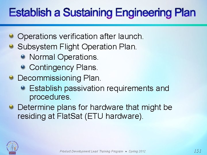
Agenda The Project Lifecycle: Phase D Responsibilities Update Staffing Needs – to I&T Deliver Supporting Documentation Deliver Subsystem and GSE to I&T Support Higher Level Integration Interface with Science Team Ship to Launch Site Support Launch Site Operations Establish Sustaining Engineering Plan Lessons Learned and Helpful Advice Product Development Lead Training Program ● Spring 2012 118

NASA Project Lifecycle Product Development Lead Training Program ● Spring 2012 119

A Major Milestone is Reached A Reason to Celebrate! PDL’s are often very happy and relieved to reach this milestone because at this phase, the subsystem design and all testing (both ambient and environmental) have been successfully completed and the subsystem has been delivered. It is ready for spacecraft or instrument level integration and test. Let the fun begin!!! Product Development Lead Training Program ● Spring 2012 120

PDL Key External Interfaces During this phase, the PDL must now also interface with the I&T Manager. Project Management Quality Assurance Systems Engineers PDL Contamination Engineers Task Management I&T Manager Product Development Lead Training Program ● Spring 2012 More Interaction 121

PDL Responsibilities What is the PDL required to do during this phase? Requirement Activity Update Staffing Needs Determine who on your team will support higher level I&T activities Deliver Supporting Documentation Generate documentation that shows how the system was designed, tested and verified Deliver Subsystem to I&T Transport to I&T and perform final stand-alone functional testing Deliver GSE Transport any test equipment required to support the test your system. Perform testing on the GSE to make sure it survived the move Integrate subsystem components at spacecraft or instrument I&T Perform or support electrical and mechanical installation and functional check-out Support Higher Level Integration and Test activities Provide test support during spacecraft or instrument I&T activities including environmental test activities Ship to Launch Site Develop a transportation plan that identifies any special requirements for the system Support Launch site operations Verify performance of subsystem Establish Sustaining Engineering Plan Determine needs for the ETU or Flat. Sat Software Migration Migrate Flight Software Management to Project Management Product Development Lead Training Program ● Spring 2012 122

Update Staffing Needs The PDLs entire development team will not support Post. Delivery I&T activities. Most often subsystem designers ramp down and are only utilized on as needed basis after delivery to I&T. However, be sure that some level of effort has been planned for their support during this phase. Confirm with project and I&T Manager the support that will be required especially for those activities that require multiple shifts. This should be documented in the manpower profile planning that occurs during Phases B/C. C&DH PDL Designer Component Designer Deputy PDL Designer GSE Lead C&DH PDL Support Mechanical Lead Product Development Lead Training Program ● Spring 2012 123

Deliver Supporting Documentation The PDL will be required to deliver supporting documentation verifying the system meets its requirements and is ready for the next level of integration. This supporting documentation is known as the End. Item-Data-Package or EIDP. Shown below are some typical contents of the EIDP. Requirements & Specifications documents List of Open Problem Reports and Problem Failure Reports Analysis Reports (Thermal, Structural, Parts Safe-to-Mate Logs Stress, Worst Case) Parts & Materials List As Built Photos Environmental Test Reports Interface Control Documents (Electrical, Mechanical, H/W-S/W) Test Plans and As-Run Test Procedures (as required) Acceptance Review Verification Matrix Product Development Lead Training Program ● Spring 2012 124

Example: Requirements Verification Matrix (MMS EPS) Product Development Lead Training Program ● Spring 2012 125

Preparing for I&T Delivery (1 of 2) Prior to official delivery to I&T, the PDL does the following: Confirm contamination requirements: The flight hardware may have to be cleaned and wrapped prior to I&T delivery. Verify, in advance, that a suitable area is available in the I&T area to support this test and that the test area meets the necessary requirements (i. e. , ESD, cleanliness, temperature and humidity). Confirm latest build of Flight Software has been completed and tested and the final build has been loaded and verified. Perform a functional checkout after the subsystem arrives at the I&T facility. This is usually performed with its GSE and it, too, must undergo a functional checkout before it is mated with the flight hardware. Product Development Lead Training Program ● Spring 2012 126

Preparing for I&T Delivery (2 of 2) The procedures for integrating the subsystem to the spacecraft or instrument must be developed prior to delivering to I&T. These procedures can usually be leveraged from existing procedures. The PDL must to work with I&T Manager in advance to define roles and responsibilities. Any special hardware handling requirements must be clearly defined. Product Development Lead Training Program ● Spring 2012 127

Preparing for I&T Delivery: Training Make sure you and your support team are properly trained to support I&T. Work with the I&T Manager to determine which training is applicable. Training Applicable Personnel ESD Training Anyone near electrical hardware Technical Certification Training As needed Safety Training As needed Magnetics Training Anyone near flight hardware Cleanroom Training Anyone going into the cleanroom Contamination Training Anyone near flight hardware WOA Users Training Anyone who touches a WOA PR System Training PDLs, Systems, Task Leads, TC’s, I&T VIPR System Training PDLs, Systems, Task Leads, TC’s, I&T Mishap Reporting Training PDLs, Systems, Task Leads, TC’s, I&T Thermal Vacuum Training Anyone working TVAC Launch Site Training Anyone going to the launch site Product Development Lead Training Program ● Spring 2012 128

If You Built It, They Will Test and Integrate It The I&T Manager during Phase D Product Development Lead Training Program ● Spring 2012 129

Supporting I&T When the subsystem is delivered for integration into the instrument or spacecraft, PDLs and their support teams often become part of a larger I&T Team in a supporting role. The Integration and Test Manager now assumes the lead role. Integration and Test Manager I&T Test Conductor Mechanical Systems PDL C&DH PDL Power System PDL Flight Software PDL Support PDL Support Product Development Lead Training Program ● Spring 2012 130

Example: MMS I&T Organization (4 Observatories) Project Management Systems OBS 1: I&T Manager OBS 1: Test Conductor Lead OBS 1: Mechanical Lead Observatory Management SMA I&T Manager CM, Schedulers, Logistics OBS 2: I&T Manager OBS 2: Test Conductor Lead OBS 2: Mechanical Lead Subsystem Support Engineers & Technicians Odd TEAM OBS 3: I&T Manager OBS 4: I&T Manager OBS 3: Test Conductor Lead OBS 3: Mechanical Lead OBS 4: Test Conductor Lead OBS 4: Mechanical Lead Subsystem Support Engineers & Technicians Even TEAM The PDL would be a part of either team Product Development Lead Training Program ● Spring 2012 131

Supporting I&T (1 of 3) During I&T, the PDL will support the I&T Manager, as required, so that the subsystem can be successfully integrated and tested. Work with I&T Manager and test conductors to train them in the use of the subsystem. PDL must relinquish ownership. Subsystem is being “handed over” and is no longer the PDL’s possession. PDLs needs to step back and realize that they no longer own the subsystem, but need to be available in case any issues come up. Product Development Lead Training Program ● Spring 2012 132

Supporting I&T (2 of 3) Shown below are some typical activities that the PDL will perform: Complete verification of any requirements that can only be verified after the system has been integrated (Ex: Impedance measurements). Support I&T stand-up meetings. Support test execution – Review and evaluation of system performance. Lead effort to resolve any subsystem issues and generate problem reports. Monitor spacecraft telemetry to assess system performance. Support spacecraft or instrument environmental testing. Close out any open paper work (Work Order Authorizations). It is a good idea to bring a binder that contains all design documentation relevant to your subsystem that can be easily referenced. Product Development Lead Training Program ● Spring 2012 133

Supporting I&T (3 of 3) The level of the PDL’s support after delivery and integration of your subsystem to I&T will depend on the project, the application of the subsystem and the defined responsibilities of the spacecraft or instrument I&T team. For example, subsystems with major spacecraft functions and interfaces (i. e. , C&DH, Power, etc. ) may expect to support post delivery I&T activities full-time. The support of post delivery activities required for the PDL of an instrument subsystem will vary depending on the project. Product Development Lead Training Program ● Spring 2012 134

Example: Typical Component Integration Sequence (MMS) Monitor chassis current during integrations. Mechanical and Thermal Installation Check chassis ground Install Break Out Box Open Circuit Power On component Verify interface Signal Characteristics Open Circuit Power Off component Send NOP command Verify interface Signal Characteristics Closed Circuit Power off, Remove BOB, Mate Flight connectors Perform Isolation and continuity measurements Connect signal lines Connect power lines Verify telemetry Run component level functional Product Development Lead Training Program ● Spring 2012 135

Example: Typical Component Integration Sequence FSW (MMS) Develop individual flight softrware Components Integrate flight software components with Engineering Test Unit hardware Run Integration Tests Perform Build Tests Product Development Lead Training Program ● Spring 2012 Deliver completed Build to FLATSAT or spacecraft 136

Product Development Lead Training Program ● Spring 2012 137

Typical I&T Tests (1 of 2) Tests must be defined and documented for all subsystems delivered to I&T. Usually this consists of an Aliveness Test, a Limited Performance Test, and a Comprehensive Performance Test. Aliveness Test (AT). A short test in which a component, IS, or Observatory is briefly powered to demonstrate that it is functional and the “intelligence” is intact. This is a demonstration that there is no gross change in performance. Aliveness tests typically run. After moving/changing GSE configurations. Changing mechanical configuration. Moving from one facility to another. Product Development Lead Training Program ● Spring 2012 138

Typical I&T Tests (2 of 2) Limited Performance Test (LPT). A subset of the CPT intended to validate full functionality within a limited time frame. Should demonstrate that the primary hardware and software functions meets performance requirements within allowable tolerances based on available GSE and environmental constraints. Typically, the LPT is executed in a single, normal operations mode. Also considered the “copper path” test. LPT Performed between environmental tests. Comprehensive Performance Test (CPT). Verifies that the observatory hardware and software meets mission requirements within the given ambient environment and configuration constraints. Performed pre- and post- environmental testing and during thermal vacuum at hot and cold plateaus. Product Development Lead Training Program ● Spring 2012 139

Example: Spacecraft Bus Integration (MMS) Install Harness onto Deck PSEES Integration C&DH Integration Battery Integration Optical Bench 1 st Integration Transponder & RF Switch Integration MOC Data Flow Test Spacecraft Deck EMI/EMC Radiated Tests Install Accel into Prop Module Install ADP Boom Into Prop Module Integrate SC Deck To Prop Module Tie down Prop To SC Deck Integrate Prop Harness Prop Functional Test Navigator Integration Prop Blanket Installation Spacecraft = Avionics, Propulsion, Harness, etc. (includes everything except the science instruments) Product Development Lead Training Program ● Spring 2012 140

Example: Observatory Integration (MMS) (1 of 2) SC Bus Functional FSW Upload Sim Command Authentication Sim GNC Phasing Test & End to End Testing FDC Testing CIDP EM to SC Electrical Integration RF Compatibility Testing DSS Integration IS Deck Delivery Integrate IS Deck to Prop Mod/SC Deck Install Struts Tie Prop to IS Deck Electrically Integrate CIDP to SC Integrate FEEPS & SCM To SC Deck IS Functional OB Alignment & Final Installation Wrap harness Install GPS Antennas Navigator End to End Test Install interior Blankets Observatory = Spacecraft + Science Instruments The Science Instruments are the Spacecraft’s payload Product Development Lead Training Program ● Spring 2012 141

Example: Observatory Integration (MMS) (2 of 2) Install Thermal Hdwr to Struts Obs Functional Install Orbital Debris Shield Install ADP Receiving Element Mag Boom Deployment Test S-Band Antenna Integration ADP Launch Lock Release Test Obs Alignment Mag Boom Integration SC Timing Test Obs CPT Product Development Lead Training Program ● Spring 2012 142

Environmental Testing Test plans and procedures must be written and released for each test: EMI/EMC. Vibration. TVAC. Other (Thermal Balance, Acoustic). Test requirements and levels defined by the project. Project Environmental Requirements Document (ERD). Spacecraft Component Level EMI/EMC Test Plan. Spacecraft Requirements Document. It is the PDL’s responsibility to coordinate with the I&T Manager to ensure subsystem can be properly tested. GSE Requirements. AC power requirements. Test fixtures (thermal plate, vibration plate, etc. ). Transportation. Product Development Lead Training Program ● Spring 2012 143

Example: Observatory Environmental Testing (MMS) EMI/EMC Radiated Qualification Tests 3 Axis Vibration Protoflight levels (Sig Sweep, Sine) Dry Tanks, AT between Axis 3 Axis Vibration Protoflight levels (Sig Sweep, Sine) Wet Tanks, AT between Axis (OBS #1 only) Observatory LPT Acoustic Test Protoflight Levels Observatory LPT Shock Test (fire Clamp band Above and Below Twice) Observatory LPT w/ Special Tests (Deployments, Prop Pressure Test, S/A ) Thermal Test Preps Full Thermal Balance Abbreviated Thermal Balance TV Test with CPT at Hot and Cold Plateaus and mission sims on transitions Flight Battery Installation Solar Array Flash Testing Mass Properties Observatory Alignment Verification Mass Properties w/AT Product Development Lead Training Program ● Spring 2012 144

Support Reviews (1 of 2) Throughout this phase, there are many reviews at which the PDL must present or support. Shown below is a list: System Acceptance Review (SAR) Examines the system, its end items and documentation, and test data and analyses that support verification. Establish that the system is ready to be delivered to I&T. Pre-Environmental Review (PER) Establishes the readiness of the system for test and evaluates the environmental test plan. Verifies that system is ready to undergo full set of environmental tests. Product Development Lead Training Program ● Spring 2012 145

Support Reviews (2 of 2) Pre-Ship Review (PSR) Assess the readiness of the observatory and/or system to be shipped to the launch range. Determines whether the Observatory and/or system flight qualification criteria has been attained. Flight Readiness Review (FRR) Review system preparedness for launch. Held at the launch site to assess the overall readiness of the total system to support the flight objectives of the mission. Product Development Lead Training Program ● Spring 2012 146

Interfacing with Project Monthly project cost and schedule reviews. Prepare charts and update schedule accordingly. Need to be on schedule and budget or suffer excruciating pain. Recovery plan will be needed to get back on schedule and within budget. Requirements Verification Matrix. All requirements have already been defined, but what is the compliance plan? How are the requirements being met? Test, Analysis, etc. Continuous Risk Assessment. Weekly status report to the project. Product Development Lead Training Program ● Spring 2012 147

Launch Site Activities (1 of 2) Pre-ship review will take place prior to transporting subsystem to launch site. PDL must demonstrate subsystem is ready to fly. In conjunction with the I&T Manager/ Transportation Lead, the PDL must develop a transportation plan. Special handling requirements. Shock sensors. Safety considerations. Product Development Lead Training Program ● Spring 2012 148

Launch Site Activities (2 of 2) Once at the launch site, procedures and plans should be in place that clearly defines how the subsystem will be tested. Could be leveraged from existing I&T procedures. Range safety will affect how/what can be tested at the launch site. Batteries. RF Transmitter. Laser. Propulsion. Flight/Launch Readiness Review. Product Development Lead Training Program ● Spring 2012 149

Launch Site Processing Arrive at Launch Processing Facility Observatory Visual Inspections Observatory CPT Observatory Leak Check Observatory Fueling Stack Observatories on PLA and each other getting final mass Encapsulation Transport to LC-41 and lift onto Atlas V I/F F-9 Umbilicals connected and EGSE STM F-8 Observatory AT F-7 MMS Powered for IST & LV Ordnance Arming Plugs installed F-5, F-4 VIF Observatory FT F-3 MOC Launch Rehearsal F-3 Ordnance Arming plugs installed, final access closeouts F-2 LV Closeouts & GSE removal F-1 Roll to Pad, Launch Countdown, Power and Config LAUNCH! Product Development Lead Training Program ● Spring 2012 150

Establish a Sustaining Engineering Plan Operations verification after launch. Subsystem Flight Operation Plan. Normal Operations. Contingency Plans. Decommissioning Plan. Establish passivation requirements and procedures. Determine plans for hardware that might be residing at Flat. Sat (ETU hardware). Product Development Lead Training Program ● Spring 2012 151

Lessons Learned and Helpful Advice (1 of 3) If there were one nugget of wisdom that I could share, it would be to pay attention when you're learning new things because it may be you that will have to do it the next time. I cannot tell you how many times that I was glad I paid attention when someone demoed or explained how to do things in a certain way. And an equal number of times that I wished I paid better attention the first time around and I ended up spending a lot of hours relearning things. Bill Yuknis – LRO C&DH PDL I experienced a failure of my subsystem during the worst possible phase of development, Phase D. It was very stressful but I had a very strong technical team to support me. Looking back, I now realize that this failure was a tremendous learning opportunity that provided me with experience that I would not otherwise gained. No matter how bad things may seem, remain positive. Beverly Settles – Swift BAT IPE PDL Product Development Lead Training Program ● Spring 2012 152

Lessons Learned and Helpful Advice (2 of 3) Surround yourself with knowledgeable people, as your team is only as good as the people in it. Know when to defer and seek input from other “seasoned” engineers and keep your eyes and ears open as you might actually learn a thing or two about putting a spacecraft together. Project management tend to emphasize cost and schedule over engineering. Engineers tend to concentrate more on development and testing and for the most part can care less about cost and schedule. It is the job of the PDL to balance the delicate act of engineering, cost, and schedule: delivering a product that works as expected on time and schedule (easier said than done). Robert Arocho – MMS PSE PDL Product Development Lead Training Program ● Spring 2012 153

Lessons Learned and Helpful Advice (3 of 3) I would say that (1) Phase D being mostly S/C I&T, they need to have a good grasp on time management since lots of hours will be required of them and their team for support and (2) To take the opportunity to grow as individuals by learning how all components are integrated and how they communicate amongst each other. Dave Raphael – MMS C&DH PDL Almost every day that you come to work, you will be faced with new situations that you never dreamed you’d be dealing with in your position. Embrace the fact that you will be asked to make decisions on topics in which you have no experience and be prepared to “find” the answers you need; either by researching the subject yourself or by working with others that may have more experience. Brian Clemmons – JWST NIRSpec FPI PDL Product Development Lead Training Program ● Spring 2012 154

PHASE E Team Members: Eric Holmes/590, Ken Mc. Caughey/596 155

Agenda Phase E Definition and Purpose Phase E Activities Role of the PDL During Phase E Ramping Down and Transitioning Product Development Lead Training Program ● Spring 2012 156

NASA Project Lifecycle Product Development Lead Training Program ● Spring 2012 157

Phase E Definition and Purpose Phase E Definition Operations and Sustainment. Phase E Purpose To Conduct the Mission and meet the initially identified need and maintain support for that need. Product Development Lead Training Program ● Spring 2012 158

Phase E Activities (1 of 6) Early Activation “Turning On” Subsystem Post Launch/Separation. Arrange for Discipline Experts to be “on console” during launch, separation, and other key phases of the early Mission Timeline. Make sure that the Design Reference Material for each subsystem element is on hand for quick access. Commissioning Management of Subsystem Support Team. Scheduling of key subsystem personnel must be planned to cover a 24 -hr schedule (typically two 12 -hr shifts). Product Development Lead Training Program ● Spring 2012 159

Phase E Activities (2 of 6) Match the expertise of the individual with the events of the timeline. Be mindful of personnel burn-out. In the excitement, it’s tempting to hang out after your shift is over. Go Home and Rest! Maintain discipline in the MOC. Understand the personalities of the team members. Calibrate for those who overreact and underreact. Individuals handle high pressure situations very differently. Product Development Lead Training Program ● Spring 2012 160

Phase E Activities (3 of 6) Evaluation of Subsystem Health. Continually monitor the health of the subsystem. Are all telemetry points as expected? If not, are they understood? Are the trends nominal and not moving toward an anomalous value? Address unexpected trends before telemetry reaches nominal limits. e. g. , Thruster Catbed Temperatures (not much direct experience before launch). Establish a Log Book to communicate activities and observations across shifts. Product Development Lead Training Program ● Spring 2012 161

Phase E Activities (4 of 6) Subsystem Characterization. Establish “real world” nominal values. Only after on-orbit use do we know what the telemetry values will be. e. g. , Star Tracker performance. Real stars, real occultations, real KF conversion. Subsystem Calibration. Some subsystems require calibration to achieve the required performance levels. Gyro Calibration. Star Tracker Alignment. Thruster Calibration. Science Instrument. Product Development Lead Training Program ● Spring 2012 162

Phase E Activities (5 of 6) Anomaly Resolution. Be prepared to execute contingency procedures as necessary. Think First – DO NO HARM. FSW Transition to Sustaining Engineering. FSW transitioned to Multi-Mission Sustaining Engineering Team. Prior to transition, ensure that budget/task for Sustaining Engineering team is in place (usually completed at the end of Phase D). Ensure that the Sustaining Engineering Plan has been completed prior to S/C Launch (usually completed towards the end of Phase D). Product Development Lead Training Program ● Spring 2012 163

Phase E Activities (6 of 6) FSW labs (including selected GSE, BB’s, ETU’s, Servers, etc. ) are moved to Sustaining Engineering Facility (currently located in Building 1). The move usually occurs when the spacecraft is in transit to the Cape, or other launch site. FSW changes to code and FSW tables are now handled by Sustaining Engineering CCB. Product Development Lead Training Program ● Spring 2012 164

Role of the PDL During Phase E Transitioning To Normal Operations. Ramp down subsystem team support as required. Turn over relevant documents or notes to the FOT. You’re Done! However, expect a phone call if an anomaly arises during the Mission Life. You will likely have an occasional consultation role as needed. Product Development Lead Training Program ● Spring 2012 165

PHASE F Team Members: Eric Holmes/590, Ken Mc. Caughey/596 166

Agenda Phase F Definition and Purpose Closeout Activities PDL Role in Closeout Other Post-Commissioning Activities Value Added Opportunities Product Development Lead Training Program ● Spring 2012 167

NASA Project Lifecycle Product Development Lead Training Program ● Spring 2012 168

Phase F Definition and Purpose Phase F Definition Closeout. Phase F Purpose To implement the systems decommissioning/disposal plan developed in Phase C and analyze any returned data and samples. Product Development Lead Training Program ● Spring 2012 169

Closeout Activities Extended Mission Evaluation. Evaluate subsystem life. Estimates can determine path forward. Can require “digging up” component test data. Can require locating subsystem experts to participate. Closeout Activities (Mission Dependent). Remove from Mission Orbit. Boost higher. Perform controlled re-entry. GRO Re-Entry. Dug out documentation from archives. Sought original subsystem engineers and designers. Passivate Spacecraft. Deplete pressurized vessels. Power down boxes. Product Development Lead Training Program ● Spring 2012 170

PDL Role in Closeout. Most have little or no role. Possible consultation role. GN&C, Propulsion, Fight Software, etc. for controlled re-entry. Product Development Lead Training Program ● Spring 2012 171

Other Post-Commissioning Activities (1 of 2) Other Post-Commissioning Activities Management of Hardware on the Ground Flight Spares Other Projects may be interested in this hardware PDLs are often best qualified to convey key information to these interested projects Can also be a historical resource for missions considering the same hardware solution ETUs Can be utilized by other projects Can be utilized for troubleshooting in the case of an anomaly Spare EEE Parts PDLs often know the availability of spare parts or they may know who to ask Product Development Lead Training Program ● Spring 2012 172

Other Post-Commissioning Activities (2 of 2) PDLs Become a Valuable Resource for Engineers on Future Projects Lessons Learned can be very valuable for other projects on Center Product Development Lead Training Program ● Spring 2012 173

Value Added Opportunities In a perfect world where PDLs had “decompression time” before being assigned their next PDL role, other valuable opportunities exist. Collect and document “Lessons Learned”. Augment an existing subsystem team and use recent experiences to assist/mentor the PDL on that team. Re-energize before taking on the next flight project. Spend some of that restored Use or Lose! Product Development Lead Training Program ● Spring 2012 174