Network Pajek Introduction Pajek is a program for


 decomposition of a large network into")


 file.")
 (see test 2.")

 *Vertices 5 1 ”a”")
 are given in the matrix form")


")


![Strong component of cite network ¥ ¥ Network/Create Partition/Components/Strong [2] Operations/Network+Partition/Extract Sub. Network [1](https://slidetodoc.com/presentation_image/2e7c077e9ed9bb4015177ae3203a6b6f/image-41.jpg "Strong component of cite network ¥ ¥ Network/Create Partition/Components/Strong [2] Operations/Network+Partition/Extract Sub. Network [1")

![Bibliographic coupling network ¥ ¥ ¥ [Read Cite. net] Network/Create New Network/Transform/1 -mode to](https://slidetodoc.com/presentation_image/2e7c077e9ed9bb4015177ae3203a6b6f/image-43.jpg "Bibliographic coupling network ¥ ¥ ¥ [Read Cite. net] Network/Create New Network/Transform/1 -mode to")
![Co-citation network ¥ ¥ ¥ ¥ [Read Cite. net] Network/Create Partitions/Degree/Output Operations/Network+Partition/Extract sub. Network](https://slidetodoc.com/presentation_image/2e7c077e9ed9bb4015177ae3203a6b6f/image-44.jpg "Co-citation network ¥ ¥ ¥ ¥ [Read Cite. net] Network/Create Partitions/Degree/Output Operations/Network+Partition/Extract sub. Network")


, then result is stored in cluster Draw the")

")


- Slides: 77
Network Pajek
Introduction ¥ Pajek is a program, for Windows, for analysis and visualization of large networks having some thousands or even millions of vertices. In Slovenian language the word pajek means spider.
Application ¥ Pajek should provide tools for analysis and visualization of such networks: ¥ ¥ ¥ ¥ ¥ collaboration networks, organic molecule in chemistry, protein-receptor interaction networks, genealogies, Internet networks, citation networks, diffusion (AIDS, news, innovations) networks, data-mining (2 -mode networks), etc. See also collection of large networks at: ¥ http: //vlado. fmf. uni-lj. si/pub/networks/data/
Main goals ¥ to support abstraction by (recursive) decomposition of a large network into several smaller networks that can be treated further using more sophisticated methods; ¥ to provide the user with some powerful visualization tools; ¥ to implement a selection of efficient (subquadratic) algorithms for analysis of large networks.
six data structures in pajek ¥ network – main object (vertices and lines - arcs, edges): ¥ ¥ partition ¥ ¥ reordering of vertices. Default extension: . per cluster ¥ ¥ Values of vertices numerical property of vertices. Default extension: . vec permutation ¥ ¥ To which cluster a vertex belongs, Nominal property of vertices. Default extension: . clu vector ¥ ¥ graph, valued network, 2 -mode or temporal network subset of vertices (e. g. a class from partition). Default extension: . cls. hierarchy ¥ hierarchically ordered clusters and vertices. Default extension: . hie
Network –. net ¥ ¥ Network can be defined in different ways on input file. Look at three of them: 1. List of neighbours (Arcslist / Edgeslist)(see test 1. net) *Vertices 5 1 ”a” 2 ”b” 3 ”c” 4 ”d” 5 ”e” *Arcslist 1 2 4 2 3 3 1 4 4 5 *Edgeslist 1 5
Explanation ¥ ¥ ¥ ¥ Data must be prepared in an input (ASCII) file. Program Note. Pad can be used for editing. Much better is a shareware editor, Text. Pad. Words, starting with *, must always be written in first column of the line. They indicate the start of a definition of vertices or lines. Using *Vertices 5 we define a network with 5 vertices. This must always be the first statement in definition of a network. Definition of vertices follows after that – to each vertex we give a label, which is displayed between “ and ”. Using *Arcslist, a list of directed lines from selected vertices are declared (1 2 4 means, that there exist two lines from vertex 1, one to vertex 2 and another to vertex 4). Similarly *Edgeslist, declares list of undirected lines from selected vertex. In the file no empty lines are allowed – empty line means end of network.
Network –. net ¥ 2. Pairs of lines (Arcs / Edges) (see test 2. net) *Vertices 5 1 ”a” 2 ”b” 3 ”c” 4 ”d” 5 ”e” *Arcs 1 2 1 1 4 1 2 3 1 1 3 4 2 4 5 1 *Edges 1 5 1
Explanation Directed lines are defined using *Arcs, undirected lines are defined using *Edges. The third number in rows defining arcs/edges gives the value/weight of the arc/edge. ¥ In the previous format (Arcslist / Edgeslist) values of lines are not defined ¥ ¥ the format is suitable only if all values of lines are 1. If values of lines are not important the third number can be omitted (all lines get value 1). ¥ In the file no empty lines are allowed – empty line means end of network. ¥
Network –. net ¥ 3. Matrix (see test 3. net) *Vertices 5 1 ”a” 2 ”b” 3 ”c” 4 ”d” 5 ”e” *Matrix 0 1 1 0 0 2 0 0 0 0 0 1 1 0 0
Explanation ¥ In this format directed lines (arcs) are given in the matrix form (*Matrix). If we want to transform bidirected arcs to edges we can use “Network>create new network>Transform>Arcs to Edges>Bidirected only”
Additional definition of network ¥ ¥ Additionally, Pajek enables precise definition of elements used for drawing networks (coordinates of vertices, shapes and colors of vertices and lines, . . . ). Example: (see test 4. net) *Vertices 5 1 “a” box 2 “b” ellipse 3 “c” diamond 4 “d” triangle 5 “e” empty. . .
Draw ¥ Layout of networks ¥ Energy: The network is presented like a physical system, and we are searching for the state with minimal energy Kamada-Kawai: using separate components, you can tile connected components in a plane ¥ Fruchterman-Reingold: draw in a plane or space and selecting the repulsion factor ¥ ¥ Eigen Values: Selecting 2 or 3 eigenvectors to become the coordinates of vertices. Can obtain nice pictures
Partition –. clu ¥ Partitions are used to describe nominal properties of vertices. ¥ e. g. , 1 -men, 2 -women ¥ Definition in input file (see test. clu) *Vertices 5 1 2 2 2 1
Vector – . vec ¥ Vectors are used to describe numerical properties of vertices (e. g. , centralities). ¥ Definition in input file (see test. vec) *Vertices 5 0. 58 0. 25 0. 08 0. 25
Pajek project files ¥ It is time consuming to load objects one by one. Therefore it is convenient to store all data in one file, called Pajek project file (. paj). (see test. paj) ¥ Project files can be produced manually by using “File>Pajek Project File>Save” ¥ To load objects stored in Pajek project file select “File>Pajek Project File>Read”
Menu structure ¥ ¥ ¥ Commands are put to menu according to the following criterion: commands that need only a network as input are available in menu Net, commands that need as input two networks are available in menu Networks, commands that need as input two objects (e. g. , network and partition) are available in menu Operations, commands that need only a partition as input are available in menu Partition. . .
Global and local views on network
Global and local views on network Local view is obtained by extracting subnetwork induced by selected cluster of vertices. ¥ Global view is obtained by shrinking vertices in the same cluster to new (compound) vertex. In this way relations among clusters of vertices are shown. ¥ Combination of local and global view is contextual view: Relations among clusters of vertices and selected vertices are shown. ¥
Example ¥ Import and export in 1994 among 80 countries are given. They is given in 1000$. (See Country_Imports. net) ¥ Partition according to continents (see Country_Continent. clu) ¥ 1 – Africa, 2 – Asia, 3 – Europe, 4 – N. America, 5 – Oceania, 6 – S. America.
Extracting Subnetwork ¥ Operations>Network+Partition>Extract Subnetwork
Removing lines with low values ¥ Network>Info>Line Values
Removing lines with low values ¥ Network>Create New Network>Transform>Remove>Lines with value>lower than (340000)
Resources ¥ Download ¥ ¥ Text file into Pajek ¥ ¥ http: //vlado. fmf. unilj. si/pub/networks/pajek/Wo. S 2 Pajek/default. htm Tutorial ¥ ¥ http: //vlado. fmf. uni-lj. si/pub/networks/pajek/howto/text 2 pajek. htm Wo. S to Pajek ¥ ¥ The latest version of Pajek is freely available, for non-commercial use, at its home page: http: //vlado. fmf. unilj. si/pub/networks/pajek/ Exploratory Social Network Analysis with Pajek visit Pajek wiki for more information ¥ http: //pajek. imfm. si/doku. php
http: //pajek. imfm. si/doku. php? id=wos 2 pajek/ WOS TO PAJEK
Web of Science S 519
Output S 519
Output S 519
wos 2 pajek ¥ The download link: ¥ http: //pajek. imfm. si/doku. php? id=wos 2 pajek ¥ The new tutorial slides: ¥ http: //pajek. imfm. si/lib/exe/fetch. php? media=f aq: wos 2 pajek 07. pdf
Monty. Lingua ¥ Download from: http: //web. media. mit. edu/~hugo/montyling ua/ ¥ Unpack it and copy ‘montylingua-2. 1’ to C: Program Files (x 86)Python 27Libsitepackages ¥ Set up a new environment variable named ‘MONTYLINGUA’ and set the variable value as C: Program Files (x 86)Python 27Libsite-
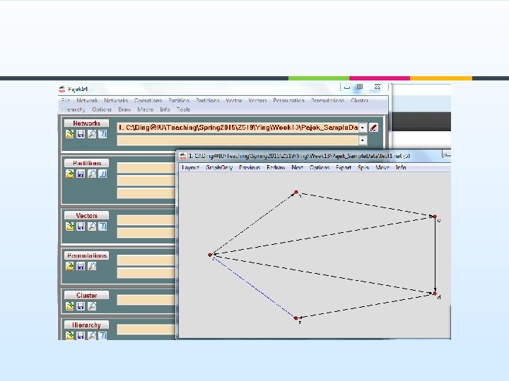
wos 2 pajek ¥ Download the latest version of Wo. S 2 Pajek. ¥ http: //pajek. imfm. si/doku. php? id=wos 2 pajek ¥ Unpack it, and double click on Wo. S 2 Pajek. py to show the main interface of program:
You can also put all wos files in a folder
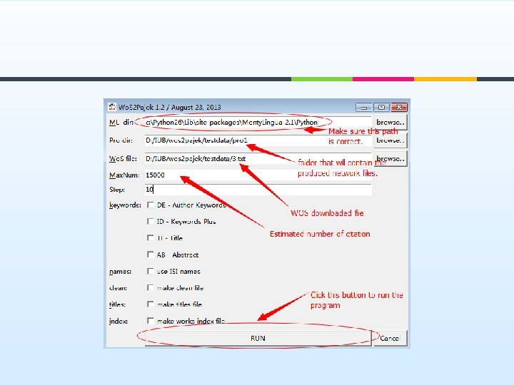
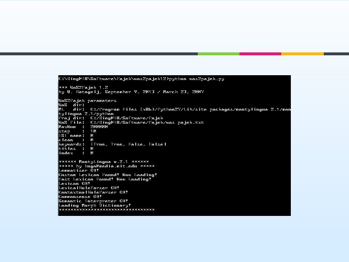
Wo. S 2 Pajek Program ¥ The current version of Wo. S 2 Pajek requires 7 parameters to be given by the user: ¥ ¥ ¥ ¥ Monty. Lingua directory: path to the directory in which the Monty. Lingua package is installed; project directory: where the output files are saved; Wo. S file; maxnum – estimate of the number of all vertices (number of records+number of cited Works) – 30*number of records; step – prints info about each k*step record as a trace; step= 0– no trace. use ISI name / short name; make a clean Wo. S file without duplicates; boolean list[DE, ID, TI, AB] specifying which fields are sources of keywords.
Wos-pajek. txt
Cite. net ¥ ¥ ¥ Network/Info/General Network/Create New Network/Transform/Remove/Loops Network/Create New Network/Transform/Remove/Multiple lines/Single line
Cite. New. net ¥ Paper citation network ¥ Questions What are highly cited articles? ¥ The diameter of the network? ¥ What are the major clusters? ¥ More questions? ¥
Strong component of cite network ¥ ¥ Network/Create Partition/Components/Strong [2] Operations/Network+Partition/Extract Sub. Network [1 -*] Operations/Network+Partition/Transform/Remove Lines/Between Cluster Save citestrong. clu
Co-author network ¥ Read WA. net Network/2 -mode network/2 -mode to 1 -mode/Columns Network/Create Partition/Components/Weak [2] Operations/Network+Partition/Extract Sub. Network[1 -*] Network/Create New Network/Transform/Remove/Loops ¥ WANew. net (which is a co-author network) ¥ Questions: ¥ ¥ ¥ The author with highest co-authors?
Bibliographic coupling network ¥ ¥ ¥ [Read Cite. net] Network/Create New Network/Transform/1 -mode to 2 mode Network/2 -mode to 1 -mode/Rows Network/Create Partition/Components/Weak [2] Operations/Network + Partition/Extract Sub. Network [1 -*]
Co-citation network ¥ ¥ ¥ ¥ [Read Cite. net] Network/Create Partitions/Degree/Output Operations/Network+Partition/Extract sub. Network [1 -*] Network/Create New Network/Transform/1 -mode to 2 mode Network/2 -mode network/2 -mode to 1 -mode/Columns Network/Create Partition/Components/Weak [2] Operations/Network+Partition/Extract Sub. Network [1 -*]
NETWORK ANALYSIS
Two-mode network ¥ One-mode network ¥ each vertex can be related to each other vertex. ¥ Two-mode network ¥ vertices are divided into two sets and vertices can only be related to vertices in the other set.
Example ¥ Suppose we have data as below: ¥ ¥ ¥ ¥ ¥ P 1: Au 1, Au 2, Au 5 P 2: Au 2, Au 4, Au 5 P 3: Au 4 See two_mode. net P 4: Au 1, Au 5 P 5: Au 2, Au 3 P 6: Au 3 P 7: Au 1, Au 5 P 8: Au 1, Au 2, Au 4 P 9: Au 1, Au 2, Au 3, Au 4, Au 5 P 10: Au 1, Au 2, Au 5 *vertices 15 10 1 "P 1" 2 "P 2" 3 "P 3" 4 "P 4" 5 "P 5" 6 "P 6" 7 "P 7" 8 "P 8" 9 "P 9" 10 "P 10" 11 "Au 1" 12 "Au 2" 13 "Au 3" 14 "Au 5" 15 "Au 5" *edgeslist 1 11 12 15 2 12 14 15 3 14 4 11 15 5 12 13 6 13 7 11 15 8 11 12 14 9 11 12 13 14 15 10 11 12 15
Transforming to valued networks ¥ The network is transformed into an ordinary network, where the vertices are elements from the first subset, using ¥ “Network>2 mode network>2 -Mode to 1 -Mode>Rows”.
Transforming to valued networks ¥ If we want to get a network with elements from the second subset we use ¥ “Network>2 mode network>2 -Mode to 1 Mode>Columns”.
Basic information about a network ¥ Basic information can be obtained by “Network>Info>General” which is available in the main window of the program. We get ¥ ¥ ¥ number of vertices number of arcs, number of directed loops number of edges, number of undirected loops density of lines Additionally we must answer the question: ¥ ¥ Input 1 or 2 numbers: +/highest, -/lowest where we enter the number of lines with the highest/lowest value or interval of values that we want to output. If we enter 10 , 10 lines with the highest value will be displayed. If we enter -10, 10 lines with the lowest value will be displayed. If we enter 3 10 , lines with the highest values from rank 3 to 10 will be displayed.
Metformin Network ¥ Load metformin network to Pajek
Entity. Metrics Entitymetrics is defined as using entities (i. e. , evaluative entities or knowledge entities) in the measurement of impact, knowledge usage, and knowledge transfer, to facilitate knowledge discovery. Ding, Y. , Song, M. , Han, J. , Yu, Q. , Yan, E. , Lin, L. , & Chambers, T. (2013). Entitymetrics: Measuring the impact of entities. PLo. S One, 8(8): 1 -14.
Entity. Metrics
Diameter of the network ¥ Network/Create New Network/Sub. Network with Paths/Info on Diameter ¥ Pajek returns only the two vertices that are the furthest away.
Component ¥ Strongly connected components ¥ ¥ ¥ Weakly connected components ¥ ¥ ¥ A weakly connected component is a maximal group of nodes that are mutually reachable by violating the edge directions. Network>Create Partition>Components>Weak Result is represented by a partition ¥ ¥ Every vertex is reachable from every other vertex Network>Create Partition>Components>Strong vertices that belong to the same component have the same number in the partition. Example ¥ component. net
Component. net
Weak Component ¥ Go to partition weak component, ¥ Partition>make network>random network>Input ¥ Visualize the new random network
Weak Component
Strong Component
Strong Component
Bicomponent ¥ A cut-vertex is a vertex whose deletion increases the number of components in the network. ¥ A bi-component is a component of minimum size 3 that does not contain a cut -vertex.
Bicomponent example
Bicomponent ¥ ¥ Network/Create New Network/. . . with Bi-Connected Components stored as Relation Numbers Bicommponents are stored in hierarchy Load USAir 97. net Get bicomponents with (14 of them) with component size >3
Bicomponent ¥ The largest component is 244 airports
Bicomponents ¥ ¥ Hierarchy>Extract Cluster (13), then result is stored in cluster Draw the cluster
Bicomponents ¥ Operations>Network+Cluster>Extract Sub. Network
Bicomponents ¥ ¥ Operations>Network+Cluster>Extract Sub. Network The info about the largest cluster (244)
Bicomponents ¥ Network>Create Partition>Degree>Input ¥ Busy airports
K-Cores ¥ ¥ ¥ A subset of vertices is called a k-core if every vertex from the subset is connected to at least k vertices from the same subset. K-Cores can be computed using “Network>Create Partitions>K-Core” and selecting Input, Output or All core. Result is a partition: for every vertex its core number is given. In most cases we are interested in the highest core(s) only. The corresponding subnetwork can be extracted using “Operations>Extract from Network>Partition” and typing the lower and upper limit for the core number. Example ¥ See k_core. net
K_core. net
Clustering Coefficients ¥ How three nodes are connected ¥ Calculation of local Clustering Coefficients: Network>Create Vector>Clustering Coefficients>CC 1 ¥ K_core. net ¥
Degree Centrality ¥ Degree centrality ¥ Network>Create Partition>Degree, or ¥ Network/Create Vector/Centrality/Degree; Example: Metformin network ¥
Betweenness Centrality ¥ ¥ How nodes are connecting different clusters Betweenness centrality ¥ Network>Create vector>Centrality>Betweenness
Betweenness Centrality ¥ The betweenness centrality value for each node
Closeness Centrality ¥ Closeness centrality ¥ ¥ Network>Create Vector>Centrality>Closeness Showing how one node is close to all other nodes in the network
Shortest Path ¥ ¥ Network/Create New Network/Sub. Network with Paths/. . . One Shortest Path between Two Vertices Enter two vertices ¥ Forget values on lines ¥ ¥ ¥ Identify vertices in source network ¥ ¥ ¥ Yes, if searching for the shortest path is based on lengths No, if searching for the shortest path is based on value of lines No Result will be a new subnetwork containing the two selected vertices Layout>Energy>Kamada Kawai>Fix first and last
Shortest Path ¥ ¥ Network/Create New Network/Sub. Network with Paths/. . . One Shortest Path between Two Vertices (17 -7045) Network/Create New Network/Sub. Network with Paths/. . . All Shortest Paths between Two Vertices (17 -7045) 17: GENE_otc 7045: GENE_ube 2 v 1