Informetric methods seminar Tutorial 2 Using Pajek for


- Slides: 30
Informetric methods seminar Tutorial 2: Using Pajek for network properties Qi Yu
Content Two mode network Basic information about a network Global and local views on network Degrees Centrality and Centralization Component Biconnected components Cores Slice Diameter Clustering Coefficients
Content Two mode network Basic information about a network Global and local views on network Degrees Centrality and Centralization Component Biconnected components Cores Slice Diameter Clustering Coefficients
Two-mode network One-mode network each vertex can be related to each other vertex. Two-mode network vertices are divided into two sets and vertices can only be related to vertices in the other set.
Example Suppose we have data as below: P 1: Au 1, Au 2, Au 5 P 2: Au 2, Au 4, Au 5 P 3: Au 4 P 4: Au 1, Au 5 P 5: Au 2, Au 3 P 6: Au 3 P 7: Au 1, Au 5 P 8: Au 1, Au 2, Au 4 P 9: Au 1, Au 2, Au 3, Au 4, Au 5 P 10: Au 1, Au 2, Au 5 *vertices 15 10 1 "P 1" 2 "P 2" 3 "P 3" 4 "P 4" 5 "P 5" 6 "P 6" 7 "P 7" 8 "P 8" 9 "P 9" 10 "P 10" 11 "Au 1" 12 "Au 2" 13 "Au 3" 14 "Au 5" 15 "Au 5" *edgeslist 1 11 12 15 2 12 14 15 3 14 4 11 15 5 12 13 6 13 7 11 15 8 11 12 14 9 11 12 13 14 15 10 11 12 15 See two_mode. net
Transforming to valued networks The network is transformed into an ordinary network, where the vertices are elements from the first subset, using If we want to get a network with elements from the second subset we use “Net>Transform>2 -Mode to 1 -Mode>Rows”. “Net>Transform>2 -Mode to 1 -Mode>Columns”. Network with or without loops can be generated: “Net>Transform>2 -Mode to 1 -Mode>Include Loops”. We store values of loops into vector using “Net>Vector>Get Loops” and use later this vector to determine We can generate network with multiple lines – for each common event a line between corresponding two women: “Net>Transform>2 -Mode to 1 -Mode>Multiple Line”.
Content Two mode network Basic information about a network Global and local views on network Degrees Centrality and Centralization Component Biconnected components Cores Slice Diameter Clustering Coefficients
Basic information about a network Basic information can be obtained by “Info>Network>General” which is available in the main window of the program. We get number of vertices number of arcs, number of directed loops number of edges, number of undirected loops density of lines Additionally we must answer the question: Input 1 or 2 numbers: +/highest, -/lowest where we enter the number of lines with the highest/lowest value or interval of values that we want to output. If we enter 10 , 10 lines with the highest value will be displayed. If we enter -10, 10 lines with the lowest value will be displayed. If we enter 3 10 , lines with the highest values from rank 3 to 10 will be displayed.
Content Two mode network Basic information about a network Global and local views on network Degrees Centrality and Centralization Component Biconnected components Cores Slice Diameter Clustering Coefficients
Global and local views on network
Global and local views on network Local view is obtained by extracting sub-network induced by selected cluster of vertices. Global view is obtained by shrinking vertices in the same cluster to new (compound) vertex. In this way relations among clusters of vertices are shown. Combination of local and global view is contextual view: Relations among clusters of vertices and selected vertices are shown.
Example Import and export in 1994 among 80 countries are given. They is given in 1000$. (See Country_Imports. net) Partition according to continents (see Country_Continent. clu) 1 – Africa, 2 – Asia, 3 – Europe, 4 – N. America, 5 – Oceania, 6 – S. America. Operations>Extract from Network>Partition Operations>Shrink Network>Partition
Content Two mode network Basic information about a network Global and local views on network Degrees Centrality and Centralization Component Biconnected components Cores Slice Diameter Clustering Coefficients
Degrees In Pajek degrees are computed using “Net>Partitions>Degree” and selecting Input, Output or All. Vertices with the highest degree can be displayed using Info>Partition. For smaller networks the result can be displayed by: double clicking the partition window, or selecting “File>Partition>Edit” or selecting the corresponding icon. Normalized degree can be found in the vector window.
Content Two mode network Basic information about a network Global and local views on network Degrees Centrality and Centralization Component Biconnected components Cores Slice Diameter Clustering Coefficients
Centrality and Centralization Degree centrality is available in “Net>Partitions>Degree”; Closeness centrality can be found in “Net>Vector>Centrality>Closeness”. Betweenness centrality can be found in “Net>Vector>Centrality>Betweenness”. When computing centrality according to degree and closeness we must additionally select Input, Output or All. In the report window the network centralization index is given. List of the selected number of most central vertices can be obtained by “Info>vector”.
Centralization expresses the extent to which a network has a center. A network is more centralized if the vertices vary more with respect to their centrality. More variation in the centrality scores of vertices yields a more centralized the network. Take degree centralization for example: Degree centralization of a network is the variation in the degrees of vertices divided by the maximum degree variation which is possible in a network of the same size. (Variation is the summed (absolute) differences between the centrality scores of the vertices and the maximum centrality score among them) Star- and line-networks.
Content Two mode network Basic information about a network Global and local views on network Degrees Centrality and Centralization Component Biconnected components Cores Slice Diameter Clustering Coefficients
Component Strongly connected components are computed using “Net>Components>Strong” Weakly connected components using “Net>Components>Weak”. Result is represented by a partition vertices that belong to the same component have the same number in the partition. Example See component. net
Content Two mode network Basic information about a network Global and local views on network Degrees Centrality and Centralization Component Biconnected components Cores Slice Diameter Clustering Coefficients
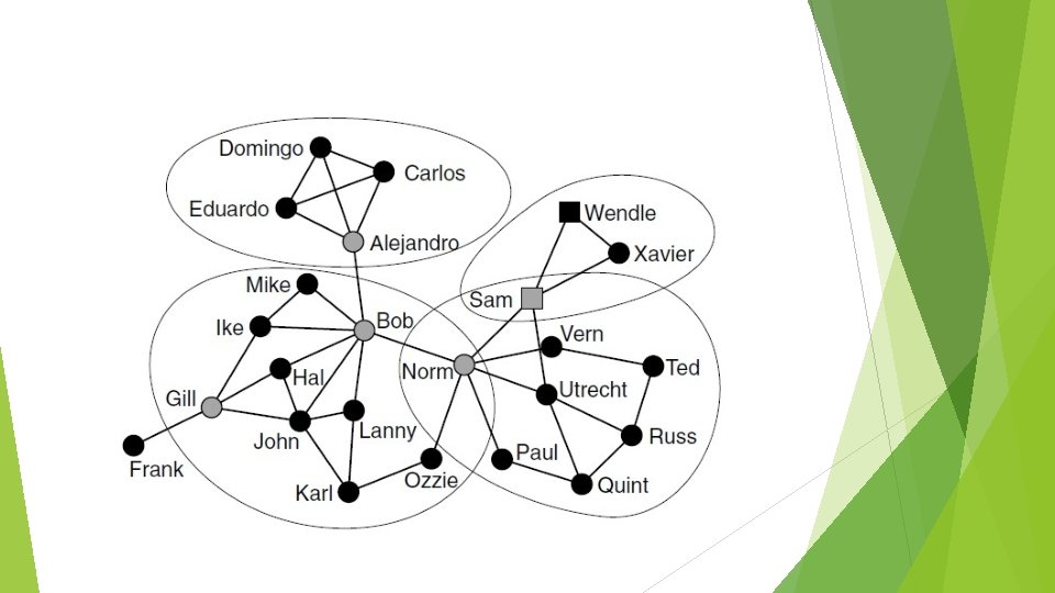
Biconnected components A cut-vertex is a vertex whose deletion increases the number of components in the network. A bi-component is a component of minimum size 3 that does not contain a cut -vertex. To compute bicomponents use: “Net>Components>Bi-components” Biconnected components are stored to hierarchy. Example See bicomponent. net
Content Two mode network Basic information about a network Global and local views on network Degrees Centrality and Centralization Component Biconnected components Cores Slice Diameter Clustering Coefficients
Cores A subset of vertices is called a k-core if every vertex from the subset is connected to at least k vertices from the same subset. Cores can be computed using “Net>Partitions>Core” and selecting Input, Output or All core. Result is a partition: for every vertex its core number is given. In most cases we are interested in the highest core(s) only. The corresponding subnetwork can be extracted using “Operations>Extract from Network>Partition” and typing the lower and upper limit for the core number. Example See k_core. net
Content Two mode network Basic information about a network Global and local views on network Degrees Centrality and Centralization Component Biconnected components Cores Slice Diameter Clustering Coefficients
Slice An m-slice is a maximal subnetwork containing the lines with a multiplicity equal to or greater than m and the vertices incident with these lines. M-slice can be calculated in Pejek by following: 1. select “Use max instead of sum” in option “Net>Partitions>Valued Core”; 2. select “Net>Partitions>Valued Core>First Threshold and Step” Result is a partition with class numbers corresponding to the highest m-slice each vertex belongs to. Example See metformin_nonloop. net
Content Two mode network Basic information about a network Global and local views on network Degrees Centrality and Centralization Component Biconnected components Cores Slice Diameter Clustering Coefficients
Diameter means the length of the longest shortest path in network. Calcultation: “net>Pathsbetween 2 vertices>diameter” Full search is performed, so the operation may be slow for very large networks (number of vertices larger than 2000) Result is – the length of the longest shortest path in network and corresponding two vertices Then we can find all the longest shortest path between above two vertices from “net>Paths between 2 vertices> All Shortest”
Content Two mode network Basic information about a network Global and local views on network Degrees Centrality and Centralization Component Biconnected components Cores Slice Diameter Clustering Coefficients
Clustering Coefficients