Optical Mineralogy Use of the petrographic microscope John







- Slides: 105
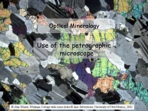
Optical Mineralogy Use of the petrographic microscope © John Winter, Whitman College with some slides © Jane Selverstone, University of New Mexico, 2003
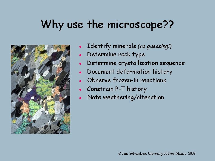
Why use the microscope? ? l l l l Identify minerals (no guessing!) Determine rock type Determine crystallization sequence Document deformation history Observe frozen-in reactions Constrain P-T history Note weathering/alteration © Jane Selverstone, University of New Mexico, 2003
The petrographic microscope Also called a polarizing microscope In order to use the scope, we need to understand a little about the physics of light, light and then learn some tools and tricks… tricks © Jane Selverstone, University of New Mexico, 2003
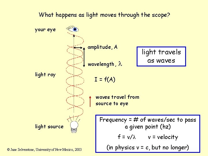
What happens as light moves through the scope? your eye amplitude, A wavelength, light ray l light travels as waves I = f(A) waves travel from source to eye light source Frequency = # of waves/sec to pass a given point (hz) f = v/l © Jane Selverstone, University of New Mexico, 2003 v = velocity (in physics v = c, but no longer)
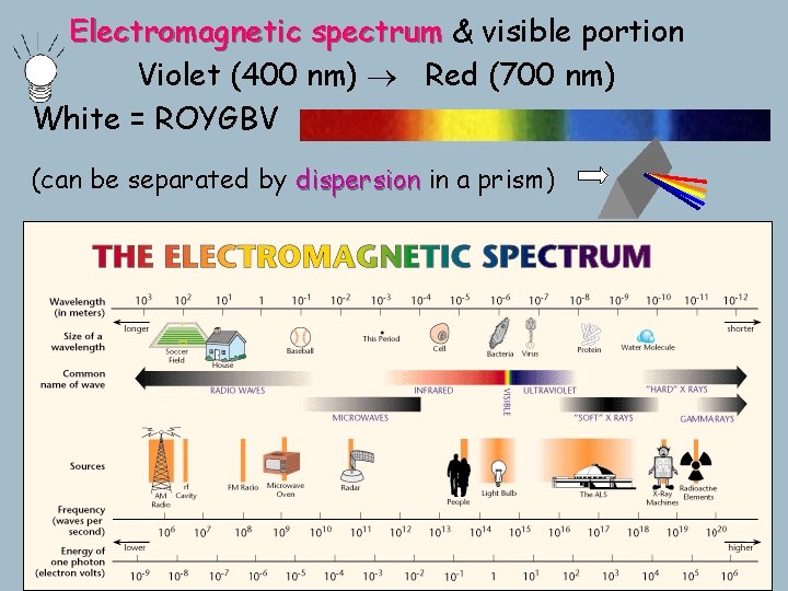
Electromagnetic spectrum & visible portion Violet (400 nm) Red (700 nm) White = ROYGBV (can be separated by dispersion in a prism)
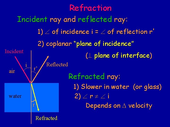
Refraction Incident ray and reflected ray: 1) of incidence i = of reflection r' 2) coplanar “plane of incidence” Incident air (^ plane of interface) i r’ Reflected Refracted ray: 1) Slower in water (or glass) 2) r i Depends on D velocity water r Refracted
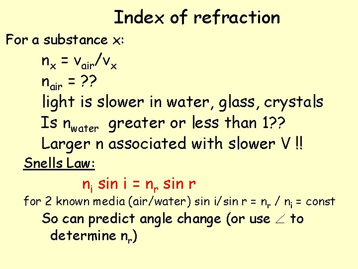
Index of refraction For a substance x: nx = vair/vx nair = ? ? light is slower in water, glass, crystals Is nwater greater or less than 1? ? Larger n associated with slower V !! Snells Law: ni sin i = nr sin r for 2 known media (air/water) sin i/sin r = nr / ni = const So can predict angle change (or use to determine nr)
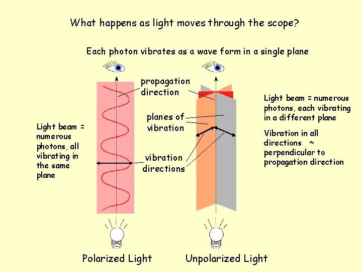
What happens as light moves through the scope? Each photon vibrates as a wave form in a single plane propagation direction Light beam = numerous photons, all vibrating in the same planes of vibration directions Polarized Light beam = numerous photons, each vibrating in a different plane Vibration in all directions ~ perpendicular to propagation direction Unpolarized Light
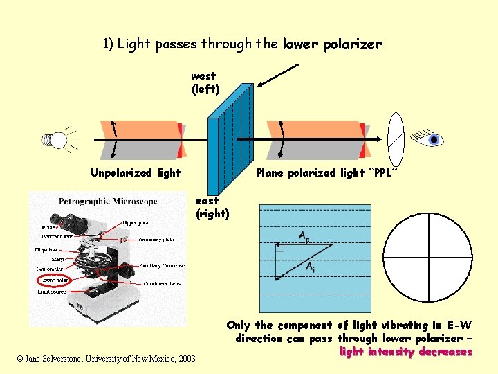
1) Light passes through the lower polarizer west (left) Unpolarized light Plane polarized light “PPL” east (right) © Jane Selverstone, University of New Mexico, 2003 Only the component of light vibrating in E-W direction can pass through lower polarizer – light intensity decreases
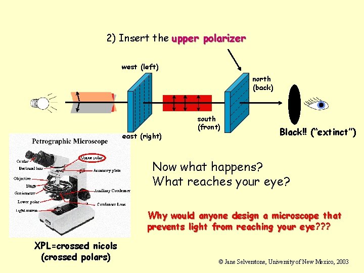
2) Insert the upper polarizer west (left) north (back) east (right) south (front) Black!! (“extinct”) Now what happens? What reaches your eye? Why would anyone design a microscope that prevents light from reaching your eye? ? ? XPL=crossed nicols (crossed polars) © Jane Selverstone, University of New Mexico, 2003
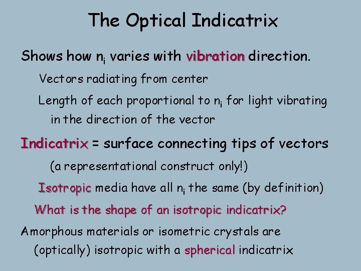
The Optical Indicatrix Shows how ni varies with vibration direction. Vectors radiating from center Length of each proportional to ni for light vibrating in the direction of the vector Indicatrix = surface connecting tips of vectors (a representational construct only!) Isotropic media have all ni the same (by definition) What is the shape of an isotropic indicatrix? Amorphous materials or isometric crystals are (optically) isotropic with a spherical indicatrix
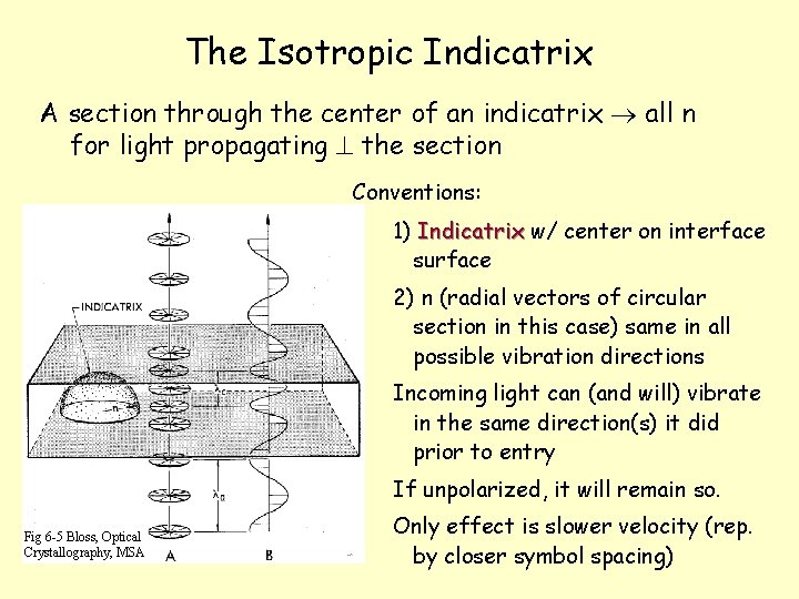
The Isotropic Indicatrix A section through the center of an indicatrix all n for light propagating ^ the section Conventions: 1) Indicatrix w/ center on interface surface 2) n (radial vectors of circular section in this case) same in all possible vibration directions Incoming light can (and will) vibrate in the same direction(s) it did prior to entry If unpolarized, it will remain so. Fig 6 -5 Bloss, Optical Crystallography, MSA Only effect is slower velocity (rep. by closer symbol spacing)
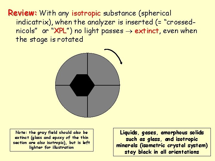
Review: With any isotropic substance (spherical indicatrix), when the analyzer is inserted (= “crossednicols” or “XPL”) XPL no light passes extinct, extinct even when the stage is rotated Note: the gray field should also be extinct (glass and epoxy of the thin section are also isotropic), but is left lighter for illustration Liquids, gases, amorphous solids such as glass, and isotropic minerals (isometric crystal system) stay black in all orientations
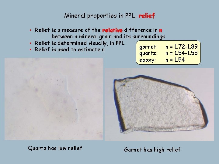
Mineral properties in PPL: relief • Relief is a measure of the relative difference in n between a mineral grain and its surroundings • Relief is determined visually, in PPL garnet: n = 1. 72 -1. 89 • Relief is used to estimate n quartz: n = 1. 54 -1. 55 epoxy: n = 1. 54 Quartz has low relief Garnet has high relief
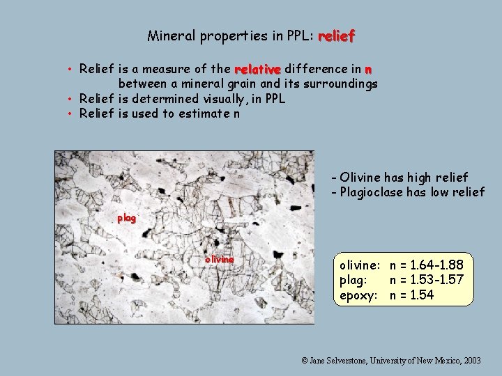
Mineral properties in PPL: relief • Relief is a measure of the relative difference in n between a mineral grain and its surroundings • Relief is determined visually, in PPL • Relief is used to estimate n - Olivine has high relief - Plagioclase has low relief plag olivine: n = 1. 64 -1. 88 plag: n = 1. 53 -1. 57 epoxy: n = 1. 54 © Jane Selverstone, University of New Mexico, 2003
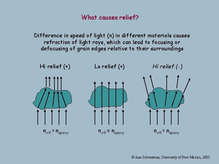
What causes relief? Difference in speed of light (n) in different materials causes refraction of light rays, which can lead to focusing or defocusing of grain edges relative to their surroundings Hi relief (+) Lo relief (+) nxtl > nepoxy nxtl = nepoxy Hi relief (-) nxtl < nepoxy © Jane Selverstone, University of New Mexico, 2003
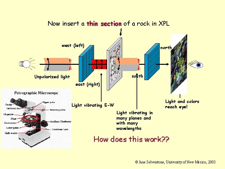
Now insert a thin section of a rock in XPL west (left) north south Unpolarized light east (right) Light vibrating E-W Light vibrating in many planes and with many wavelengths Light and colors reach eye! How does this work? ? © Jane Selverstone, University of New Mexico, 2003
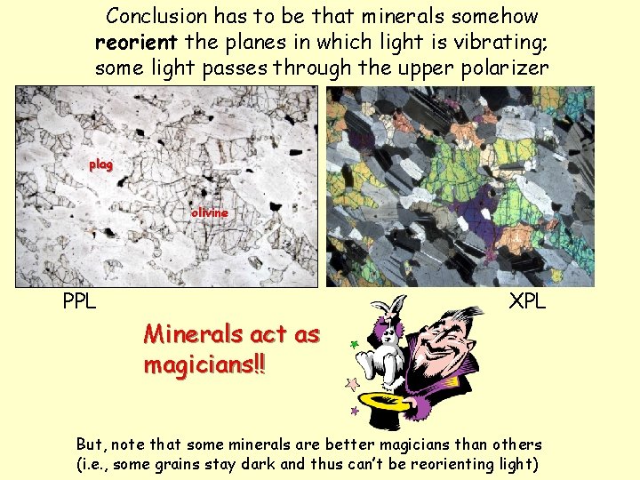
Conclusion has to be that minerals somehow reorient the planes in which light is vibrating; some light passes through the upper polarizer plag olivine PPL Minerals act as magicians!! XPL But, note that some minerals are better magicians than others (i. e. , some grains stay dark and thus can’t be reorienting light)
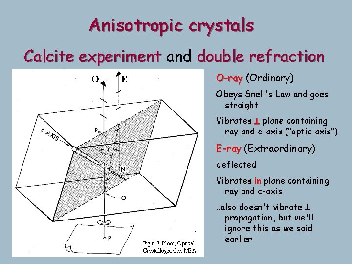
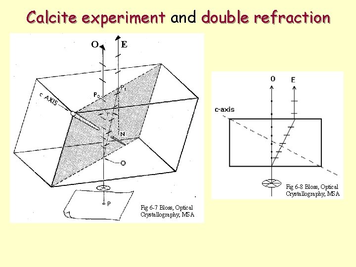
Anisotropic crystals Calcite experiment and double refraction O O-ray (Ordinary) Double images: E Obeys Snell's Law and goes Ray 2 rays with straight different Vibrates ^ plane containing propagation andaxis”) ray and c-axis (“optic vibration directions E-ray (Extraordinary) deflected Each is polarized ( ^ Vibrates plane containing eachinother) ray and c-axis Fig 6 -7 Bloss, Optical Crystallography, MSA . . also doesn't vibrate ^ propagation, but we'll ignore this as we said earlier
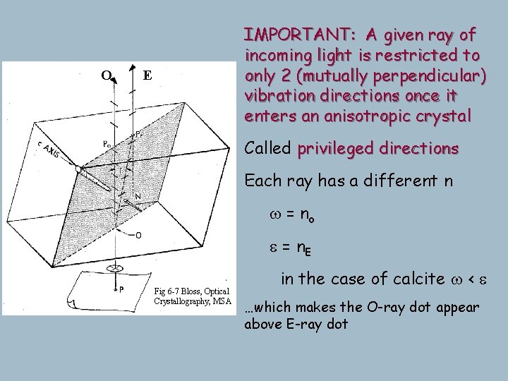
O IMPORTANT: A given ray of incoming light is restricted to Both rays vibrate parallel to only 2 (mutually perpendicular) the incident surface forit vibration directions once normalanincident light, crystal so the enters anisotropic interface x-section of the indicatrix is stilldirections valid, even Called privileged for the E-ray Each ray has a different n Thus our simplification of w = no ^ propagation works vibration well e = enough n E E Fig 6 -7 Bloss, Optical Crystallography, MSA From nowcase on we'll treat these in the of calcite w<e two rays as collinear, but not …which makes the O-ray dot appear interacting, because it's the above E-ray dot vibration direction that counts
Some generalizations and vocabulary l l l Amorphous materials and isometric minerals (e. g. , garnet) are isotropic – they cannot reorient light. These minerals are always extinct in crossed polars (XPL). All other minerals are anisotropic – they are all capable of reorienting light (acting as magicians). All anisotropic minerals contain one or two special propagation directions that do not reorient light. s Minerals with one special direction are called uniaxial s Minerals with two special directions are called biaxial © Jane Selverstone, University of New Mexico, 2003
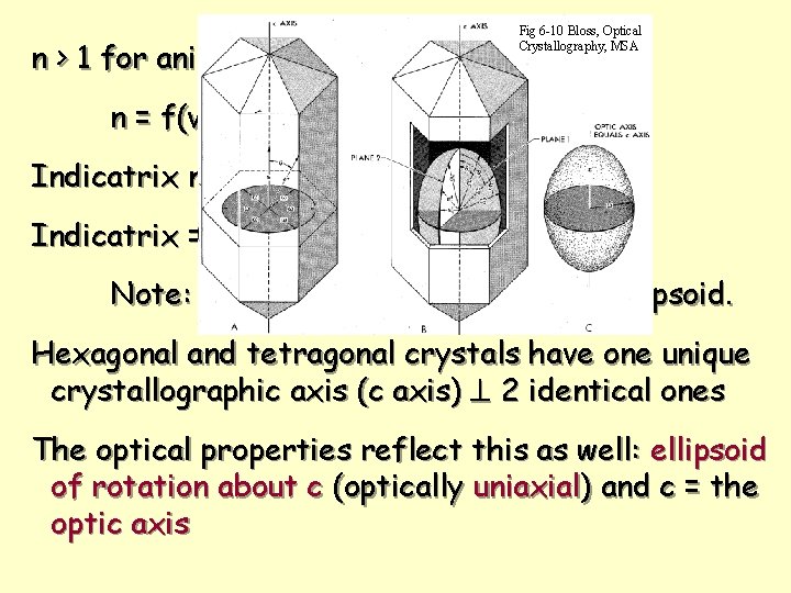
n > 1 for anisotropic substances Fig 6 -10 Bloss, Optical Crystallography, MSA n = f(vibration direction) Indicatrix no longer a sphere Indicatrix = ellipsoid Note: continuous function, smooth ellipsoid. Hexagonal and tetragonal crystals have one unique crystallographic axis (c axis) ^ 2 identical ones The optical properties reflect this as well: ellipsoid of rotation about c (optically uniaxial) and c = the optic axis
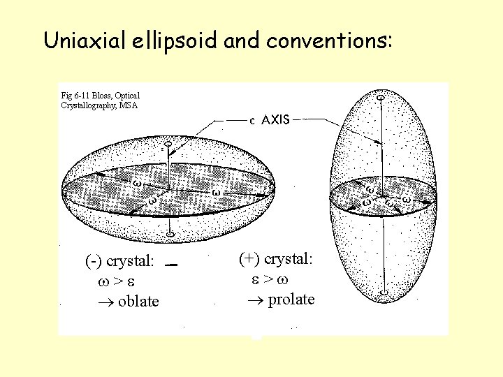
Uniaxial ellipsoid and conventions: Fig 6 -11 Bloss, Optical Crystallography, MSA (-) crystal: w>e oblate (+) crystal: e>w prolate
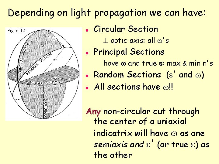
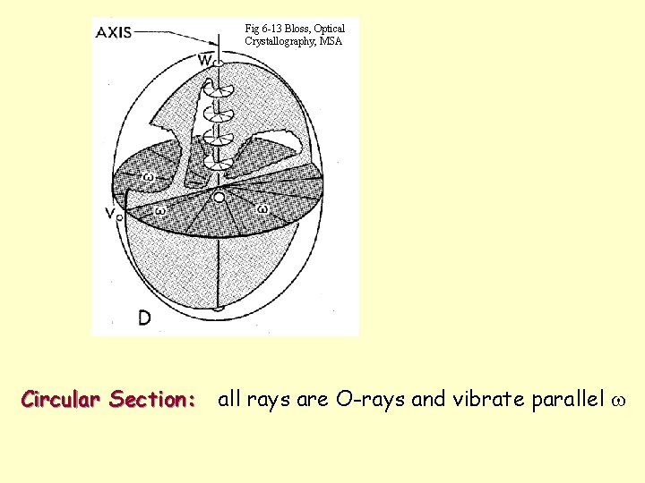
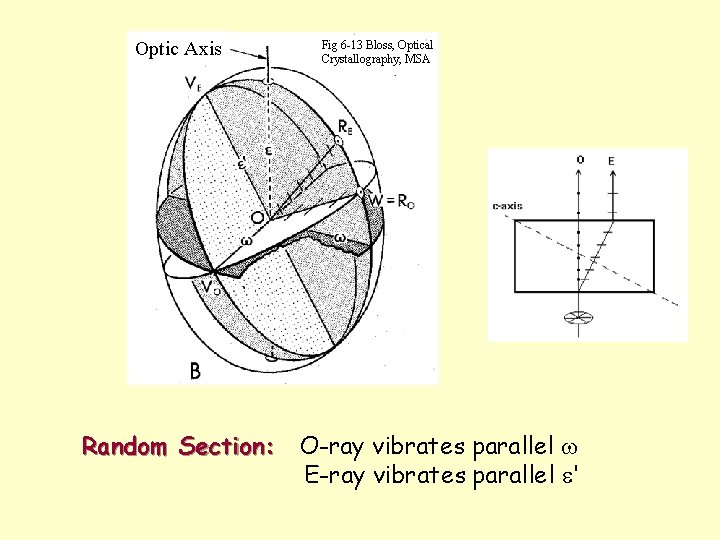
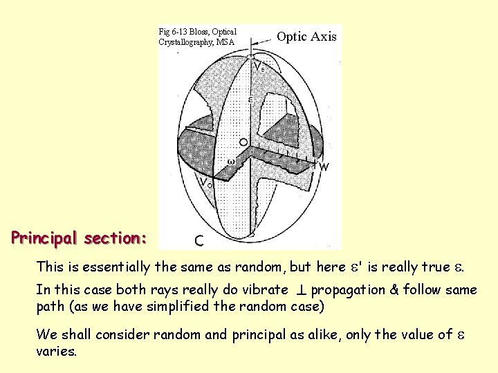
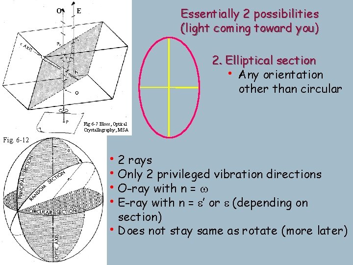
Depending on light propagation we can have: Fig. 6 -12 l Circular Section ^ optic axis: all w's l Principal Sections have w and true e: max & min n's l l Random Sections (e' and w) All sections have w!! Any non-circular cut through the center of a uniaxial indicatrix will have w as one semiaxis and e' (or true e) as the other
Calcite experiment and double refraction O E Fig 6 -8 Bloss, Optical Crystallography, MSA Fig 6 -7 Bloss, Optical Crystallography, MSA
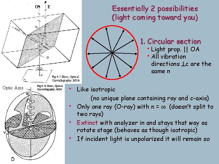
Fig 6 -13 Bloss, Optical Crystallography, MSA Circular Section: all rays are O-rays and vibrate parallel w
Optic Axis Fig 6 -13 Bloss, Optical Crystallography, MSA Random Section: O-ray vibrates parallel w E-ray vibrates parallel e'
Fig 6 -13 Bloss, Optical Crystallography, MSA Optic Axis Principal section: This is essentially the same as random, but here e' is really true e. In this case both rays really do vibrate ^ propagation & follow same path (as we have simplified the random case) We shall consider random and principal as alike, only the value of varies. e
O Essentially 2 possibilities (light coming toward you) E 1. Circular section • Light prop. || OA • All vibration directions ^c are the same n Fig 6 -7 Bloss, Optical Crystallography, MSA Optic Axis Fig 6 -13 Bloss, Optical Crystallography, MSA • Like isotropic • • • (no unique plane containing ray and c-axis) Only one ray (O-ray) with n = w (doesn’t split to two rays) Extinct with analyzer in and stays that way as rotate stage (behaves as though isotropic) If incident light is unpolarized it will remain so
O Essentially 2 possibilities (light coming toward you) E 2. Elliptical section • Any orientation other than circular Fig 6 -7 Bloss, Optical Crystallography, MSA Fig. 6 -12 • 2 rays • Only 2 privileged vibration directions • O-ray with n = w • E-ray with n = e’ or e (depending on section) • Does not stay same as rotate (more later)
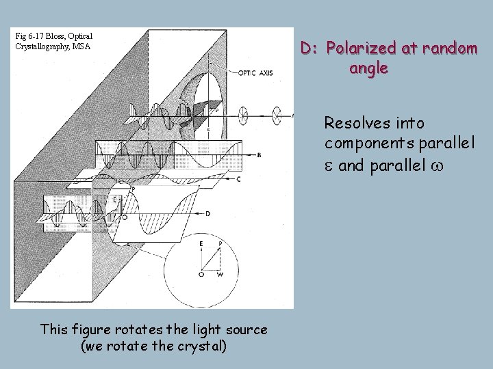
Fig 6 -17 Bloss, Optical Crystallography, MSA B-C: Polarized parallel e and w at random D: Polarized Transmits only one ray! (no angle component parallel to the other privileged direction) Note convention here: Resolves into Light slows upon entering xl. components parallel Since frequency (& color) is e same, and parallel wis about the slowing illustrated by more compressed wave forms (they spend more time in the xl), so vibrate more times (vibrate more per length traveled) A: Unpolarized Ray splits into This figure rotates the light source (we rotate the crystal) e and w
Rotating the stage Anisotropic minerals with an elliptical indicatrix section change color as the stage is rotated; these grains go black 4 times in 360° rotation-exactly every 90 o polarizer Isotropic: glass or isometric minerals or look down optic axis of anisotropic minerals
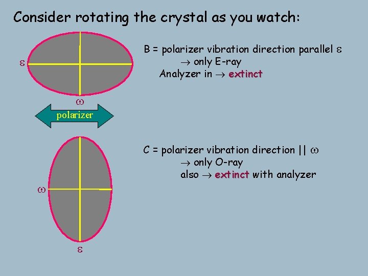
Consider rotating the crystal as you watch: B = polarizer vibration direction parallel only E-ray Analyzer in extinct e w polarizer C = polarizer vibration direction || w only O-ray also extinct with analyzer w e e
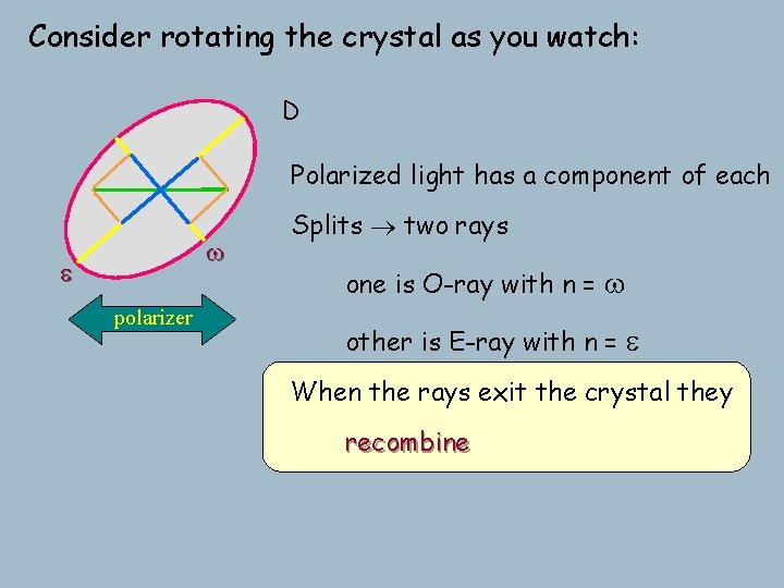
Consider rotating the crystal as you watch: D Polarized light has a component of each w e polarizer Splits two rays one is O-ray with n = w other is E-ray with n = e When the rays exit the crystal they recombine
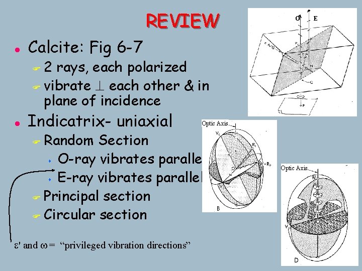
REVIEW l O Calcite: Fig 6 -7 2 rays, each polarized F vibrate ^ each other & in plane of incidence F l Indicatrix- uniaxial Optic Axis Random Section s O-ray vibrates parallel w s E-ray vibrates parallel e' F Principal section F Circular section F e' and w = “privileged vibration directions” Optic Axis E
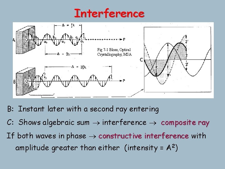
Interference Fig 7 -1 Bloss, Optical Crystallography, MSA A: Particles inlater phase if displaced from rest position Path Difference (D) =with distance between any 2 points by on asame waveamount form in B: Instant a second ray entering same direction usually expressed as xl C: F Shows algebraic sum interference composite ray F a 1 - a 2 - a 3 are all in phase F D between any 2 points in phase = il (i=any integer) F b 1 - b 2 - b 3 are also all in phase (but not with a 1…) If both waves in phase constructive interference with (2 i+1) F D between anyout 2 of points out of phasedisplacement =( / 2) l l particles perfectly phase: equal-but-opposite phaseperf. 2 amplitude greater than either (intensity = A ) s b 1 and c 1 are not, since in an instant it won't work
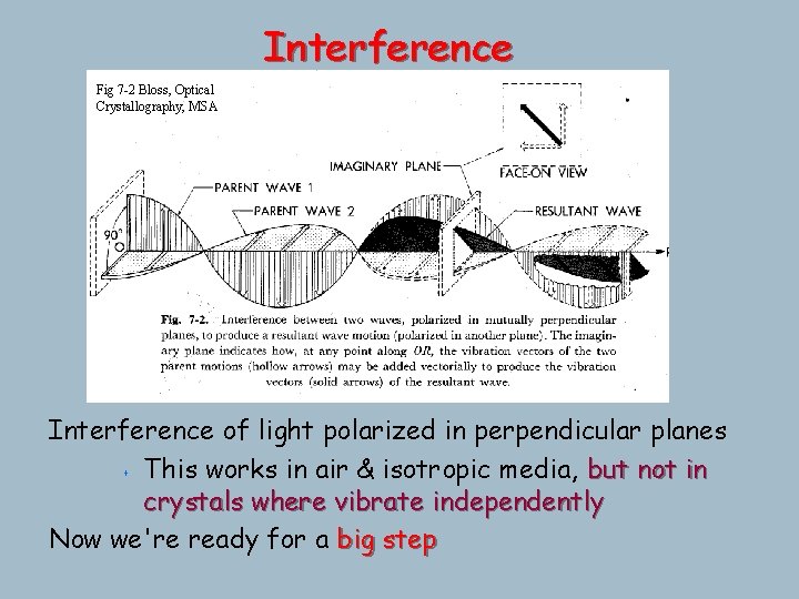
Interference Fig 7 -2 Bloss, Optical Crystallography, MSA Interference of light polarized in perpendicular planes s This works in air & isotropic media, but not in crystals where vibrate independently Now we're ready for a big step
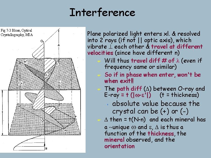
Interference Fig 7 -3 Bloss, Optical Crystallography, MSA Plane polarized light enters xl. & resolved into 2 rays (if not || optic axis), which vibrate ^ each other & travel at different velocities (since have different n) F Will thus travel diff # of l (even if frequency same or similar) F So if in phase when enter, won't be when exit!! F The path diff dif (D) between O-ray and E-ray = t (|w-e'|) (t = thickness) s F absolute value because the crystal can be (+) or (-) D then = t(N-n) and each mineral has a ~unique w and e, D is thus a function of the thickness, thickness the mineral observed, and the orientation
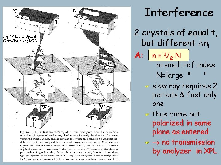
Interference N N S S 2 crystals of equal t, but different Dni A: n = 1/2 N Fig 7 -4 Bloss, Optical Crystallography, MSA F W E F F n=small ref index N=large " " slow ray requires 2 periods & fast only one thus come out polarized in same plane as entered no transmission by analyzer in XPL
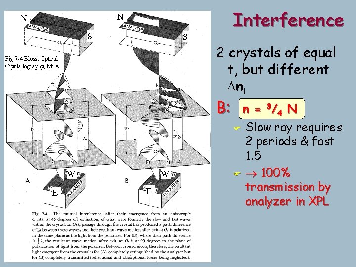
Interference N N S S 2 crystals of equal t, but different Dni Fig 7 -4 Bloss, Optical Crystallography, MSA B: W E n = 3/ 4 N F Slow ray requires 2 periods & fast 1. 5 F 100% transmission by analyzer in XPL
Transmission by the Analyzer Determined by: a) Angle between analyzer and polarizer (fixed at 90 o) b) Angle between polarizer and closest privileged direction of xl s s When polarizer || either privileged vibration direction extinct, since only one ray & it's cancelled Every crystal goes extinct 4 times in 360 o rotation (unless isotropic)
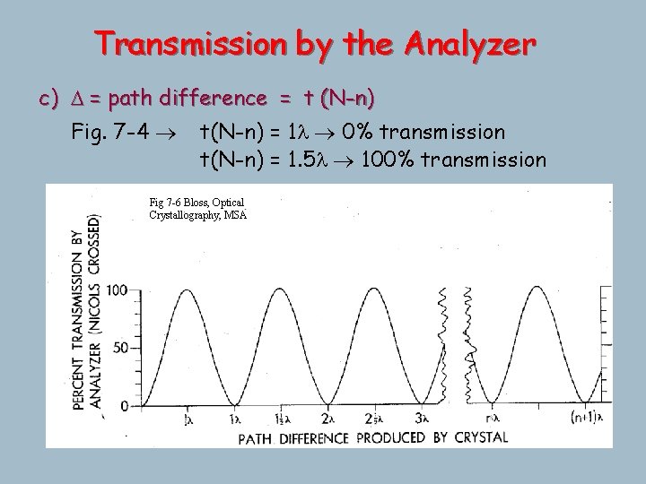
Transmission by the Analyzer c) D = path difference = t (N-n) Fig. 7 -4 t(N-n) = 1 l 0% transmission t(N-n) = 1. 5 l 100% transmission Fig 7 -6 Bloss, Optical Crystallography, MSA
Transmission by the Analyzer Determined by: d) l of light a new concept s in part (c) D has been expressed in terms of l s . . . but it's really an absolute retardation, some finite # of nm (or A or miles…) s If the transmitted light is white (mixed), each wavelength will be retarded t(N-n) by the same absolute distance, which will be a different x/l
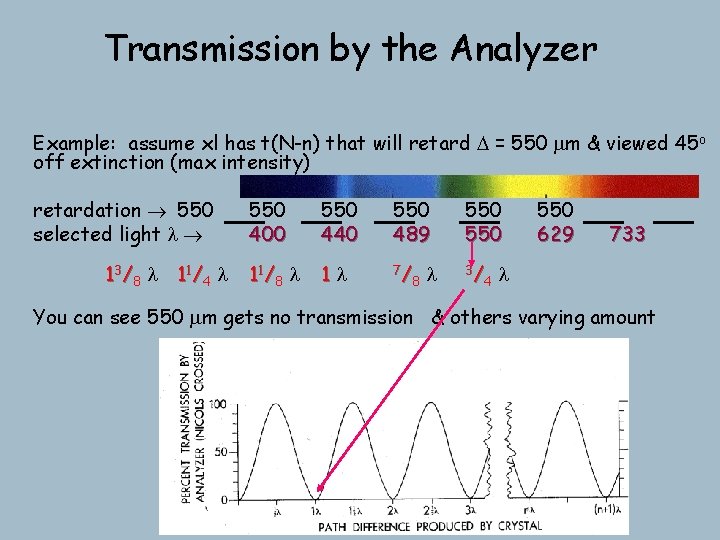
Transmission by the Analyzer Example: assume xl has t(N-n) that will retard D = 550 mm & viewed 45 o off extinction (max intensity) retardation 550 selected light l 13/8 l 11/4 l 550 400 550 440 550 489 550 11 / 8 l 1 l 7/ 8 3/ 4 l 550 629 733 l You can see 550 mm gets no transmission & others varying amount
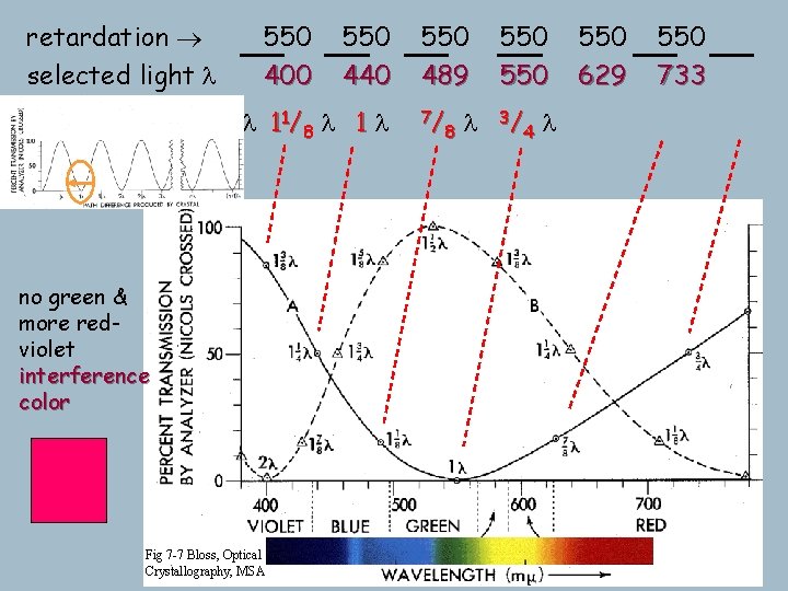
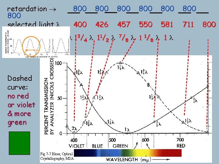
retardation selected light l 550 400 550 440 1 3 / 8 l 1 1/ 4 l 1 1/ 8 l 1 l no green & more redviolet interference color Fig 7 -7 Bloss, Optical Crystallography, MSA 550 489 550 7/ 8 3/ 4 l l 550 629 550 733
retardation 800 selected light l 2 l 800 800 800 400 426 457 550 581 711 1 7 / 8 l 1 3 / 4 l 1 1/ 2 l 7 / 8 l 1 1/ 8 l 1 l Dashed curve: no red or violet & more green Fig 7 -7 Bloss, Optical Crystallography, MSA 800
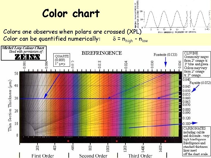
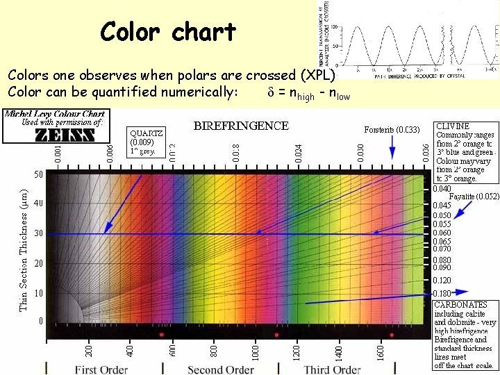
Color chart Colors one observes when polars are crossed (XPL) Color can be quantified numerically: d = nhigh - nlow
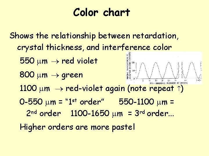
Color chart Shows the relationship between retardation, crystal thickness, and interference color 550 mm red violet 800 mm green 1100 mm red-violet again (note repeat ) 0 -550 mm = “ 1 st order” 550 -1100 mm = 2 nd order 1100 -1650 mm = 3 rd order. . . Higher orders are more pastel
Estimating birefringence 1) Find the crystal of interest showing the highest colors (D depends on orientation) 2) Go to color chart thickness = 30 microns use 30 micron line + color, follow radial line through intersection to margin & read birefringence Suppose you have a mineral with second-order green What about third order yellow?
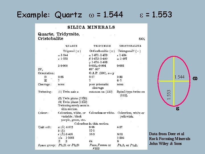
e = 1. 553 1. 544 1. 553 Example: Quartz w = 1. 544 e Data from Deer et al Rock Forming Minerals John Wiley & Sons w
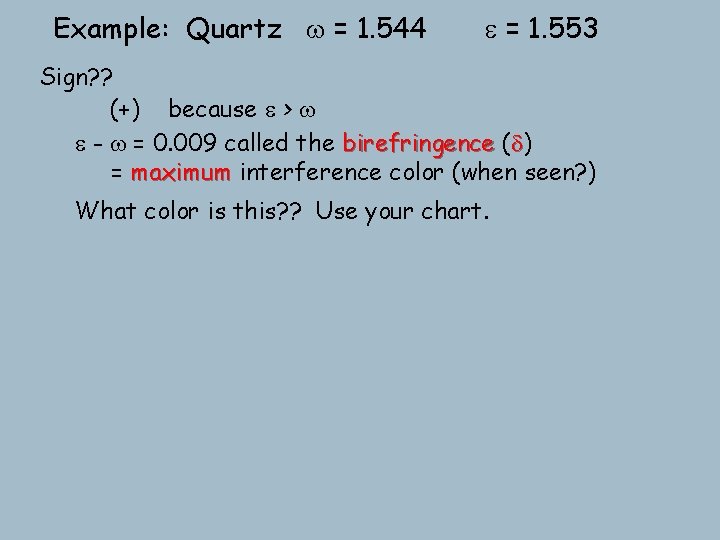
Example: Quartz w = 1. 544 e = 1. 553 Sign? ? (+) because e > w e - w = 0. 009 called the birefringence (d) = maximum interference color (when seen? ) What color is this? ? Use your chart.
Color chart Colors one observes when polars are crossed (XPL) Color can be quantified numerically: d = nhigh - nlow
Example: Quartz w = 1. 544 e = 1. 553 Sign? ? (+) because e > w e - w = 0. 009 called the birefringence (d) = maximum interference color (when see this? ) What color is this? ? Use your chart. For other orientations get e' - w progressively lower color Rotation of the stage changes the intensity, but not the hue Extinct when either privileged direction N-S (every 90 o) and maximum interference color brightness at 45 o 360 o rotation 4 extinction positions exactly 90 o apart
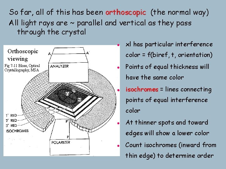
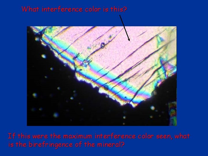
So far, all of this has been orthoscopic (the normal way) All light rays are ~ parallel and vertical as they pass through the crystal l Orthoscopic viewing Fig 7 -11 Bloss, Optical Crystallography, MSA xl has particular interference color = f(biref, t, orientation) l Points of equal thickness will have the same color l isochromes = lines connecting points of equal interference color l At thinner spots and toward edges will show a lower color l Count isochromes (inward from thin edge) to determine order
What interference color is this? If this were the maximum interference color seen, what is the birefringence of the mineral?
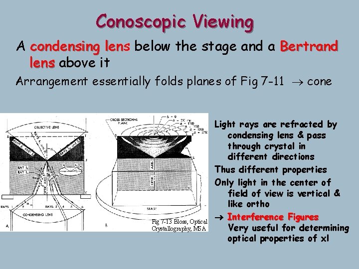
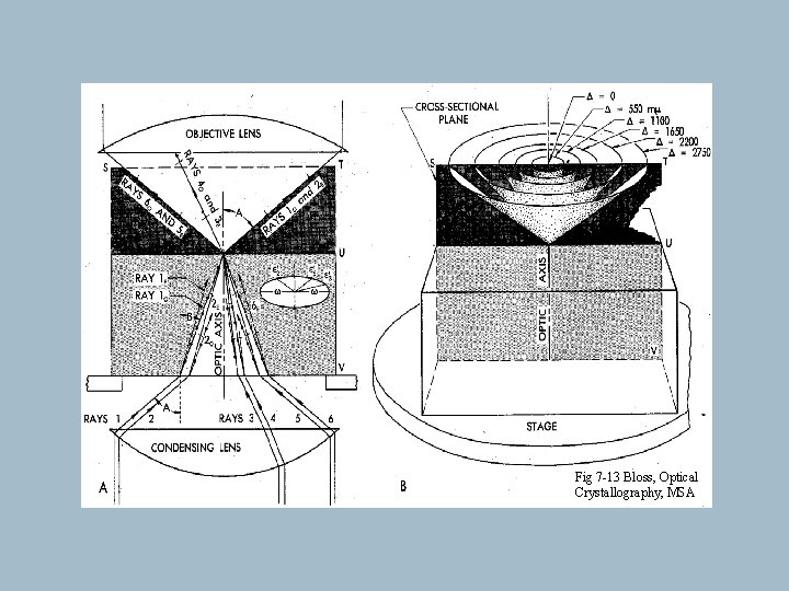
Conoscopic Viewing A condensing lens len below the stage and a Bertrand lens above it Arrangement essentially folds planes of Fig 7 -11 cone Fig 7 -13 Bloss, Optical Crystallography, MSA Light rays are refracted by condensing lens & pass through crystal in different directions Thus different properties Only light in the center of field of view is vertical & like ortho ® Interference Figures Very useful for determining optical properties of xl
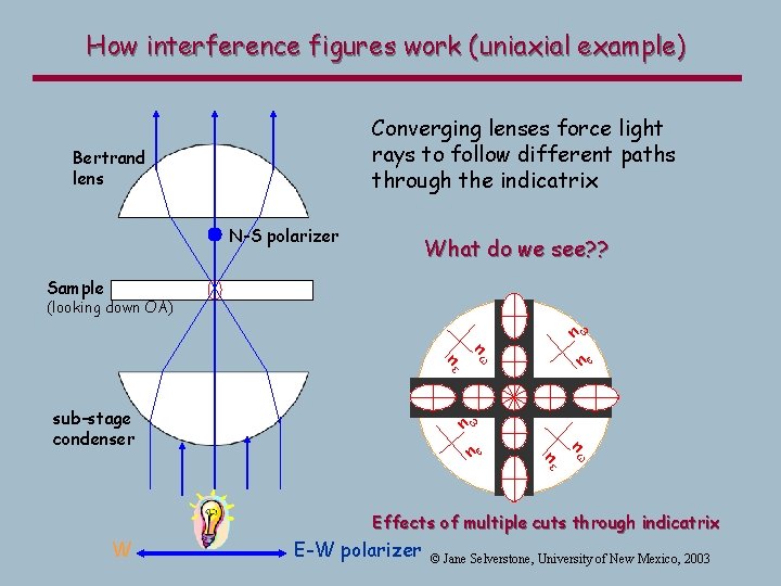
How interference figures work (uniaxial example) Converging lenses force light rays to follow different paths through the indicatrix Bertrand lens N-S polarizer What do we see? ? Sample (looking down OA) n e sub-stage condenser nw n ne w nw ne n w Effects of multiple cuts through indicatrix W E-W polarizer © Jane Selverstone, University of New Mexico, 2003
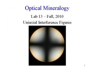
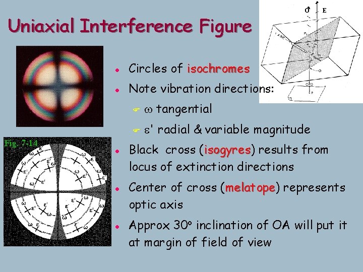
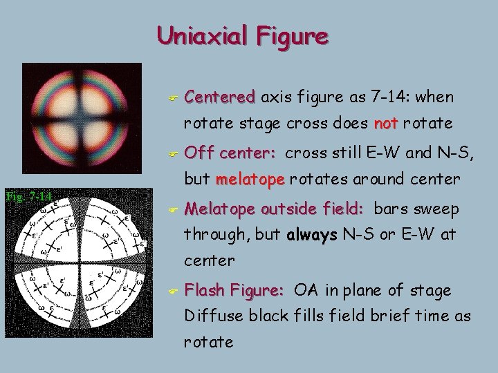
Uniaxial Interference Figure Fig. 7 -14 l Circles of isochromes l Note vibration directions: l l l O F w tangential F e' radial & variable magnitude E Black cross (isogyres) isogyres results from locus of extinction directions Center of cross (melatope) melatope represents optic axis Approx 30 o inclination of OA will put it at margin of field of view
Uniaxial Figure F Centered axis figure as 7 -14: when rotate stage cross does not rotate F Off center: cross still E-W and N-S, but melatope rotates around center Fig. 7 -14 F Melatope outside field: bars sweep through, but always N-S or E-W at center F Flash Figure: OA in plane of stage Diffuse black fills field brief time as rotate
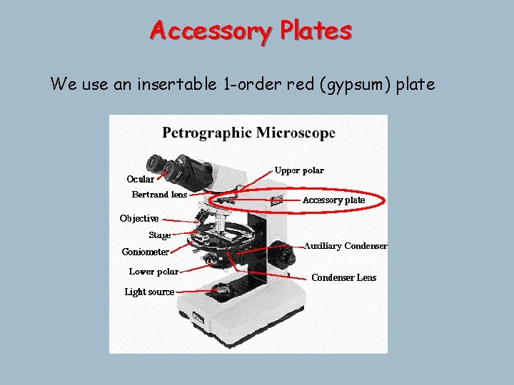
Accessory Plates We use an insertable 1 -order red (gypsum) plate
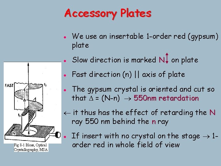
Accessory Plates l We use an insertable 1 -order red (gypsum) plate l Slow direction is marked N on plate l Fast direction (n) || axis of plate l The gypsum crystal is oriented and cut so that D = (N-n) 550 nm retardation it thus has the effect of retarding the N ray 550 nm behind the n ray l Fig 8 -1 Bloss, Optical Crystallography, MSA If insert with no crystal on the stage 1 order red in whole field of view
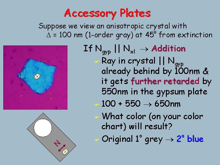
Accessory Plates N Suppose we view an anisotropic crystal with D = 100 nm (1 -order gray) at 45 o from extinction If Ngyp || Nxl Addition F Ray in crystal || Ngyp already behind by 100 nm & it gets further retarded retarde by 550 nm in the gypsum plate F 100 + 550 650 nm F What color (on your color chart) will result? o o F Original 1 grey 2 blue
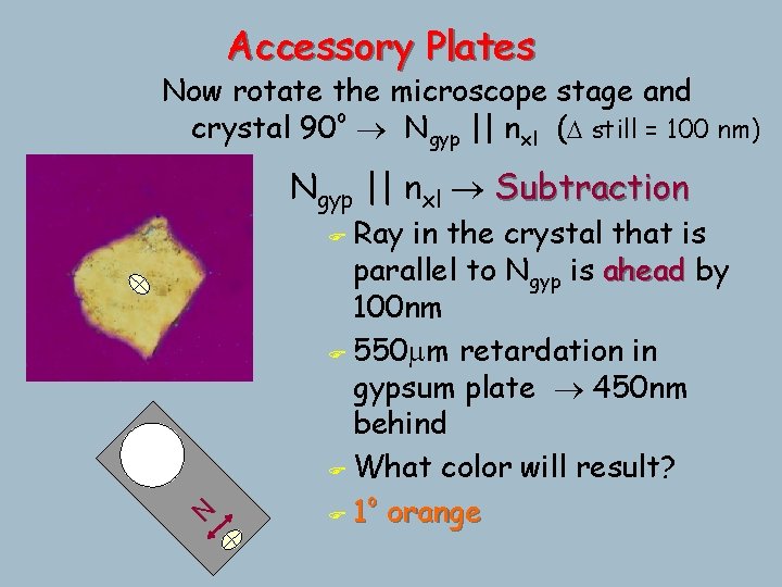
Accessory Plates Now rotate the microscope stage and crystal 90 o Ngyp || nxl (D still = 100 nm) Ngyp || nxl Subtraction Ray in the crystal that is parallel to Ngyp is ahead by 100 nm F 550 mm retardation in gypsum plate 450 nm behind F What color will result? o F 1 orange N F
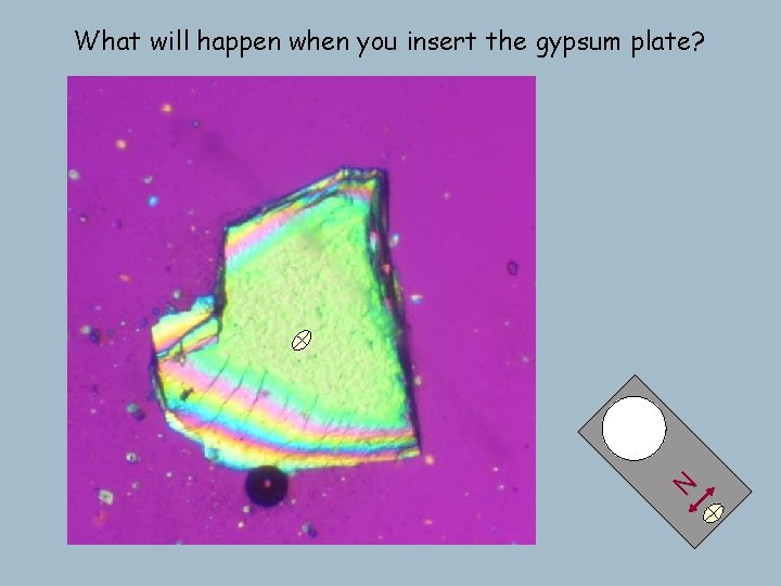
N What will happen when you insert the gypsum plate?
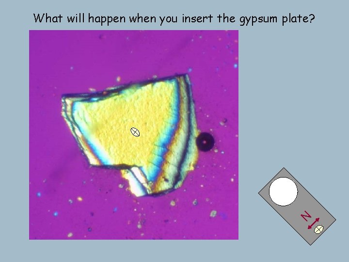
N What will happen when you insert the gypsum plate?
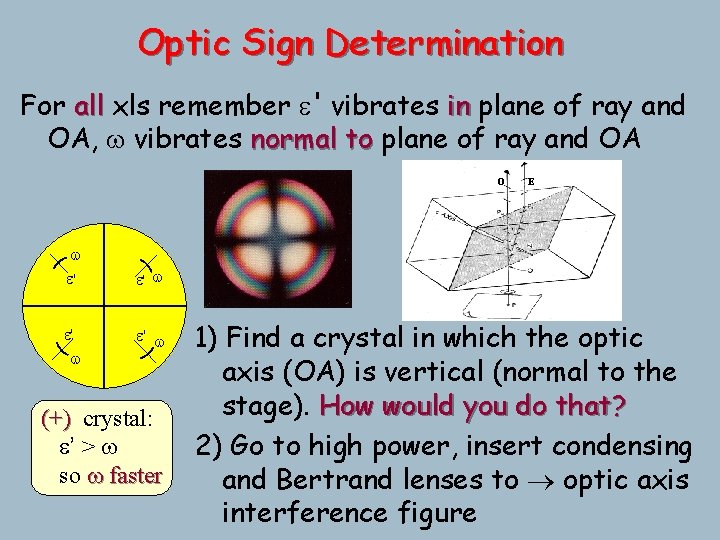
Optic Sign Determination For all xls remember e' vibrates in plane of ray and OA, w vibrates normal to plane of ray and OA O w e' e' w E e' w (+) crystal: e’ > w so w faster 1) Find a crystal in which the optic axis (OA) is vertical (normal to the stage). How would you do that? 2) Go to high power, insert condensing and Bertrand lenses to optic axis interference figure
Fig 7 -13 Bloss, Optical Crystallography, MSA
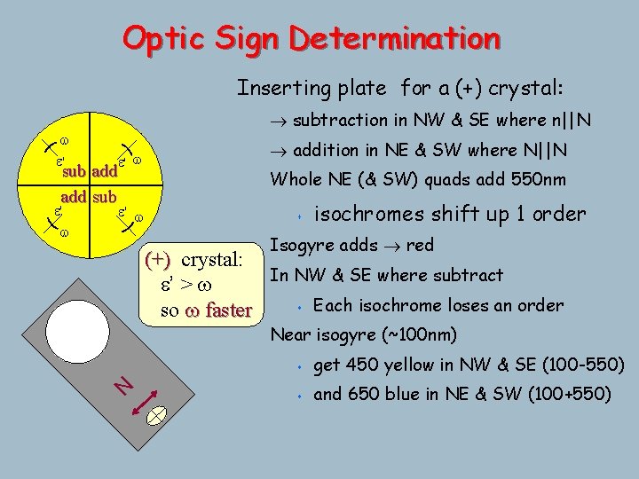
Optic Sign Determination Inserting plate for a (+) crystal: w e' subtraction in NW & SE where n||N e' w sub add sub e' w Whole NE (& SW) quads add 550 nm s isochromes shift up 1 order Isogyre adds red (+) crystal: In NW & SE where subtract e’ > w s Each isochrome loses an order so w faster Near isogyre (~100 nm) N e' w addition in NE & SW where N||N s get 450 yellow in NW & SE (100 -550) s and 650 blue in NE & SW (100+550)
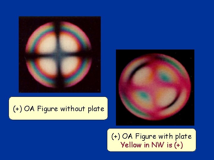
(+) OA Figure without plate (+) OA Figure with plate Yellow in NW is (+)
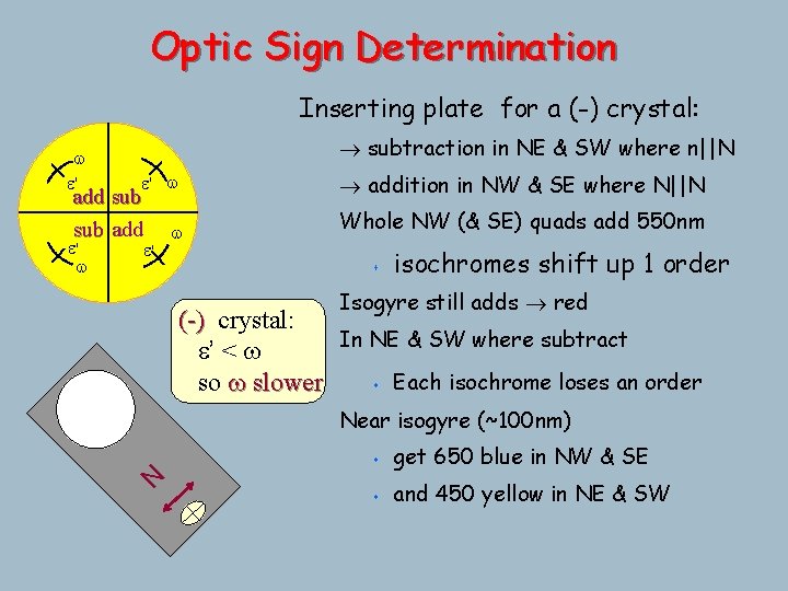
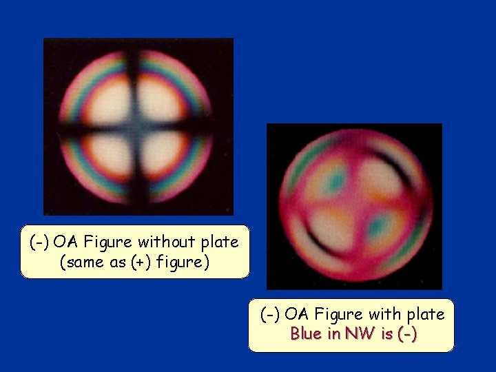
Optic Sign Determination Inserting plate for a (-) crystal: w e' subtraction in NE & SW where n||N e' w addition in NW & SE where N||N w Whole NW (& SE) quads add 550 nm add sub add e' s isochromes shift up 1 order Isogyre still adds red (-) crystal: In NE & SW where subtract e’ < w s Each isochrome loses an order so w slower Near isogyre (~100 nm) s get 650 blue in NW & SE s and 450 yellow in NE & SW N e' w
(-) OA Figure without plate (same as (+) figure) (-) OA Figure with plate Blue in NW is (-)
Orienting crystals to determine w and e Can determine the refractive index of a mineral by crushing a bit up and immersing the grains in a series of oils of known refractive index. When the crystal disappears perfectly nmineral = noil The trick is to isolate w and true e by getting each E-W (parallel to the polarized light)
Orienting crystals to determine w and e To measure w only (if all grains of a single mineral): 1) Find a grain with low interference colors- ideally a grain that remains extinct as the stage is rotated 2) (check for centered OA figure) 3) Determine optic sign while you're at it (for use later) 4) Back to orthoscopic : all rays are w 5) Compare nxl to noil
Orienting crystals to determine w and e Now look at the other crystals of the same mineral: If the crystals are randomly oriented in a slide or thin section you may see any interference color from grayblack (OA vertical) to the highest color possible for that mineral (OA in plane of stage and see w and true e).
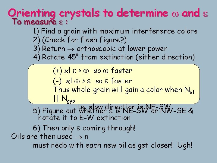
Orienting crystals to determine w and e To measure e : 1) Find a grain with maximum interference colors 2) (Check for flash figure? ) 3) Return orthoscopic at lower power o 4) Rotate 45 from extinction (either direction) (+) xl e > w so w faster (-) xl w > e so e faster Thus whole grain will gain a color when Nxl || Ngyp i. e. slow direction is NE-SW 5) Figure out whether e is NE-SW or NW-SE & rotate it to E-W extinction 6) Then only e coming through! Oils are then used n must redo with each new oil as get closer! Ugh!
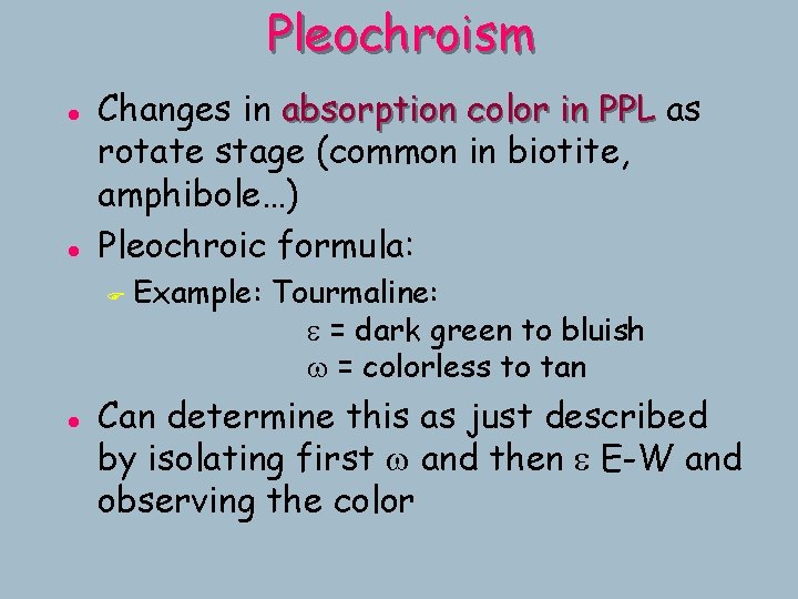
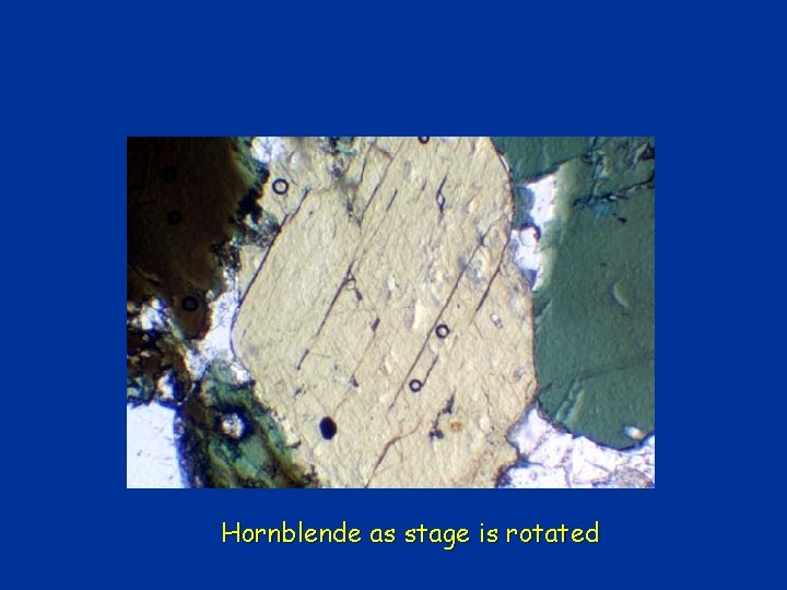
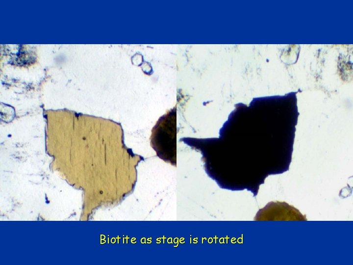
Pleochroism l l Changes in absorption color in PPL as rotate stage (common in biotite, amphibole…) Pleochroic formula: F l Example: Tourmaline: e = dark green to bluish w = colorless to tan Can determine this as just described by isolating first w and then e E-W and observing the color
Hornblende as stage is rotated
Biotite as stage is rotated
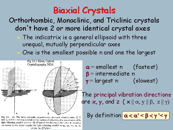
Biaxial Crystals Orthorhombic, Monoclinic, and Triclinic crystals don't have 2 or more identical crystal axes F F The indicatrix is a general ellipsoid with three unequal, mutually perpendicular axes One is the smallest possible n and one the largest Fig 10 -1 Bloss, Optical Crystallography, MSA a = smallest n (fastest) b = intermediate n g = largest n (slowest) The principal vibration directions are x, y, and z ( x || a, y || b, z || g) By definition a < a' < b < g '< g
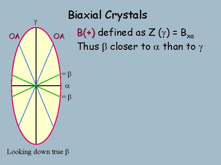
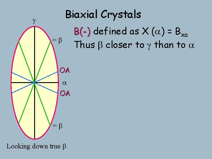
g Biaxial Crystals If a < b < g then there must be some point between a & g with n = b Because = b in plane, and true b is normal to plane, then the section containing both is a circular section Has all of the properties of a circular =b section! a If look down it: F all rays = b F no preferred vibration direction F polarized incoming light will remain so F unpolarized “ “ F thus appear isotropic as rotate stage Looking down true b
g Biaxial Crystals If a < b < g then there must be some point between a & g with n = b OA ^ optic axis by definition =b a Looking down true b
Biaxial Crystals g OA OA If a < b < g then there must be some point between a & g with n = b ^ optic axis by definition =b a =b Looking down true b And there must be two! Biaxial Orthorhombic, Monoclinic, and Triclinic minerals are thus biaxial and Hexagonal and tetragonal minerals are uniaxial
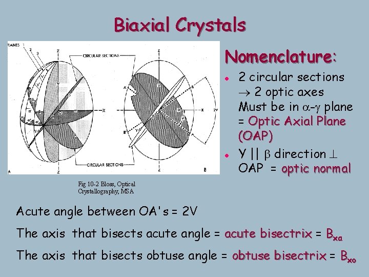
Biaxial Crystals Nomenclature: l l 2 circular sections 2 optic axes Must be in a-g plane = Optic Axial Plane (OAP) Y || b direction ^ OAP = optic normal Fig 10 -2 Bloss, Optical Crystallography, MSA Acute angle between OA's = 2 V The axis that bisects acute angle = acute bisectrix = Bxa The axis that bisects obtuse angle = obtuse bisectrix = Bxo
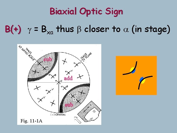
Biaxial Crystals g OA OA =b a =b Looking down true b B(+) defined as Z (g) = Bxa Thus b closer to a than to g
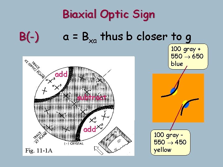
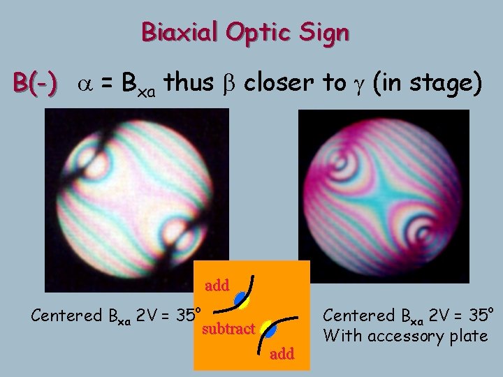
Biaxial Crystals g B(-) defined as X (a) = Bxa Thus b closer to g than to a =b OA a OA =b Looking down true b
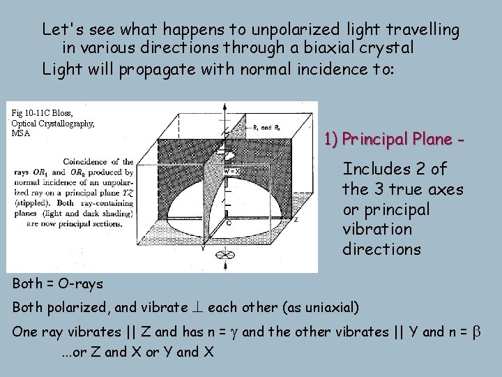
Let's see what happens to unpolarized light travelling in various directions through a biaxial crystal Light will propagate with normal incidence to: Fig 10 -11 C Bloss, Optical Crystallography, MSA 1) Principal Plane Includes 2 of the 3 true axes or principal vibration directions Both = O-rays ^ each other (as uniaxial) One ray vibrates || Z and has n = g and the other vibrates || Y and n = b Both polarized, and vibrate . . . or Z and X or Y and X
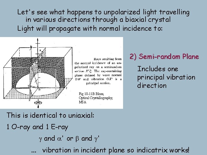
Let's see what happens to unpolarized light travelling in various directions through a biaxial crystal Light will propagate with normal incidence to: 2) Semi-random Plane Includes one principal vibration direction Fig 10 -11 B Bloss, Optical Crystallography, MSA This is identical to uniaxial: 1 O-ray and 1 E-ray g and a' or b and g'. . . vibration in incident plane so indicatrix works!
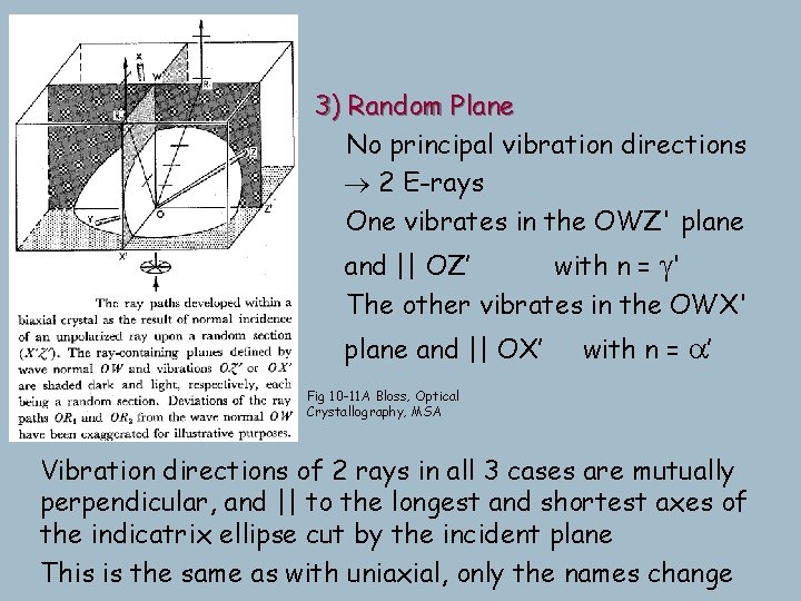
3) Random Plane No principal vibration directions 2 E-rays One vibrates in the OWZ' plane and || OZ’ with n = g' The other vibrates in the OWX' plane and || OX’ with n = a’ Fig 10 -11 A Bloss, Optical Crystallography, MSA Vibration directions of 2 rays in all 3 cases are mutually perpendicular, and || to the longest and shortest axes of the indicatrix ellipse cut by the incident plane This is the same as with uniaxial, only the names change
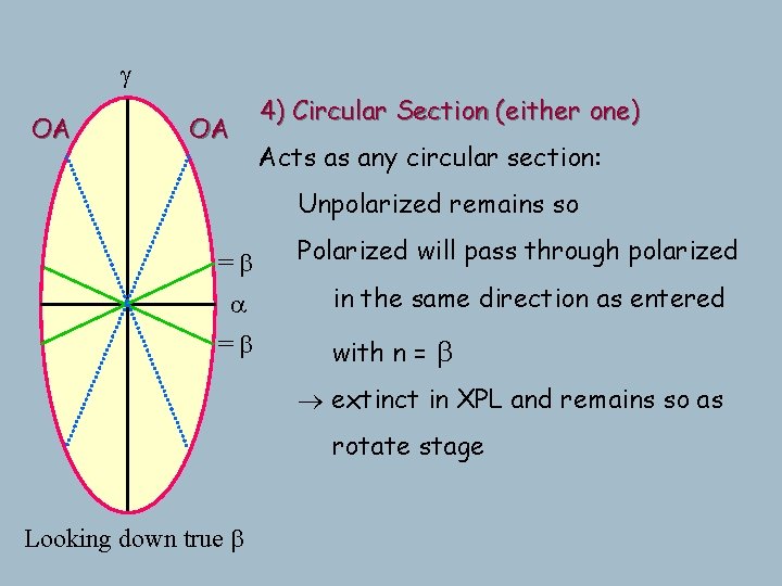
g OA OA 4) Circular Section (either one) Acts as any circular section: Unpolarized remains so =b a =b Polarized will pass through polarized in the same direction as entered with n = b extinct in XPL and remains so as rotate stage Looking down true b
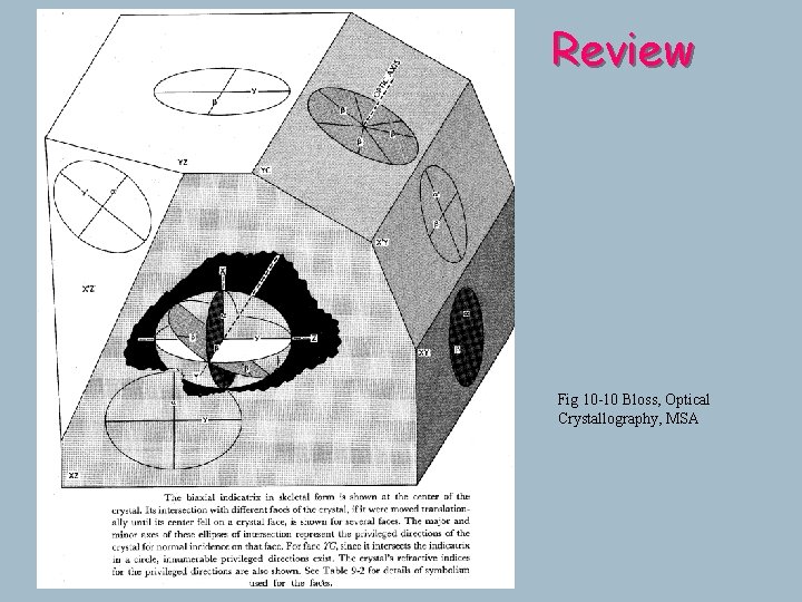
Review Fig 10 -10 Bloss, Optical Crystallography, MSA
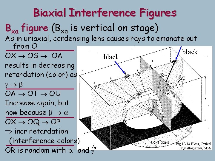
Biaxial Interference Figures Bxa figure (Bxa is vertical on stage) As in uniaxial, condensing lens causes rays to emanate out from O black OX OS OA black results in decreasing retardation (color) as g b OA OT OU Increase again, but now because b a OX OQ OP incr retardation (interference colors) Fig 10 -14 Bloss, Optical Crystallography, MSA OR is random with a' and g'
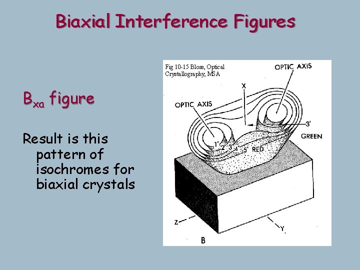
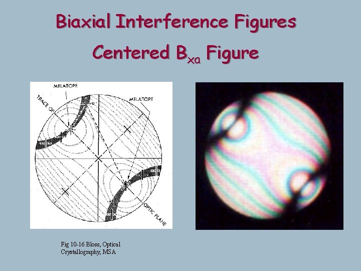
Biaxial Interference Figures Fig 10 -15 Bloss, Optical Crystallography, MSA Bxa figure Result is this pattern of isochromes for biaxial crystals
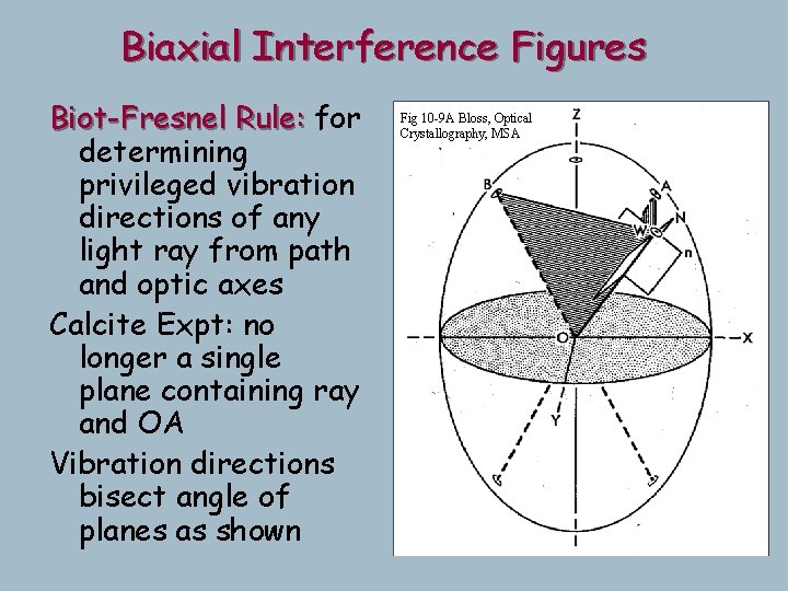
Biaxial Interference Figures Biot-Fresnel Rule: for determining privileged vibration directions of any light ray from path and optic axes Calcite Expt: no longer a single plane containing ray and OA Vibration directions bisect angle of planes as shown Fig 10 -9 A Bloss, Optical Crystallography, MSA
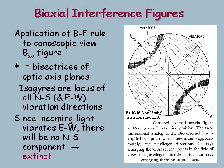
Biaxial Interference Figures Application of B-F rule to conoscopic view Bxa figure + = bisectrices of optic axis planes Isogyres are locus of all N-S (& E-W) vibration directions Since incoming light vibrates E-W, there will be no N-S component extinct Fig 10 -16 Bloss, Optical Crystallography, MSA
Biaxial Interference Figures Centered Bxa Figure Fig 10 -16 Bloss, Optical Crystallography, MSA
Biaxial Interference Figures Same figure rotated 45 o Optic axes are now E-W Clearly isogyres must swing Demonstration Fig 10 -16 B Bloss, Optical Crystallography, MSA
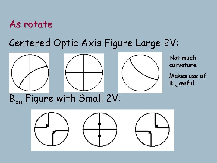
As rotate Centered Optic Axis Figure Large 2 V: Not much curvature Makes use of Bxa awful Bxa Figure with Small 2 V:
Always use optic axis figures F Easiest to find anyway. Why? o l Bxo looks like Bxa with 2 V > 90 l Random Figures: Isogyre sweeps through field (not parallel x-hair at intersection, so can recognize from uniaxial even with this odd direction) F Useless if far from OA
Biaxial Optic Sign B(-) a = Bxa thus b closer to g 100 gray + 550 650 blue add subtract add Fig. 11 -1 A 100 gray 550 450 yellow
Biaxial Optic Sign B(-) a = Bxa thus b closer to g (in stage) add Centered Bxa 2 V = 35 o subtract add Centered Bxa 2 V = 35 o With accessory plate
Biaxial Optic Sign B(+) g = Bxa thus b closer to a (in stage) sub add sub Fig. 11 -1 A
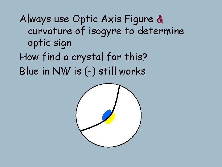
Always use Optic Axis Figure & curvature of isogyre to determine optic sign How find a crystal for this? Blue in NW is (-) still works
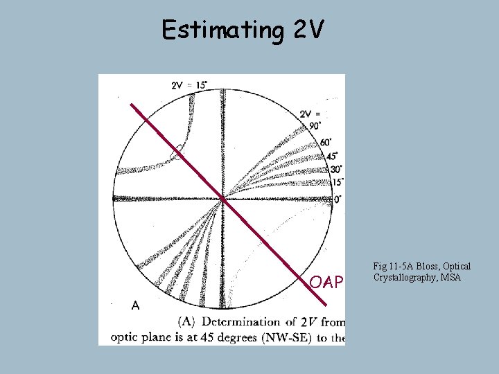
Estimating 2 V OAP Fig 11 -5 A Bloss, Optical Crystallography, MSA
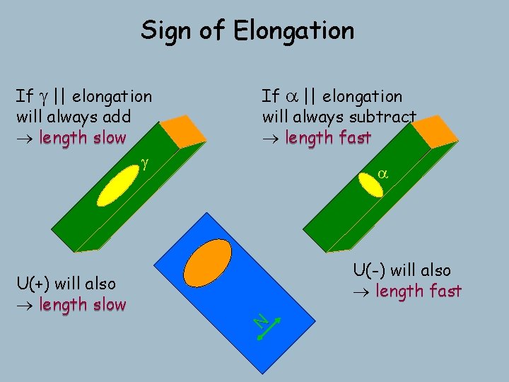
Sign of Elongation If g || elongation will always add length slow g If a || elongation will always subtract length fast a U(-) will also length fast N U(+) will also length slow
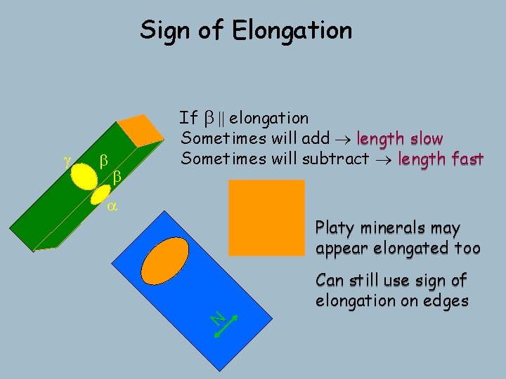
Sign of Elongation b b a Platy minerals may appear elongated too Can still use sign of elongation on edges N g If b || elongation Sometimes will add length slow Sometimes will subtract length fast