RealTime Imaging v Fluoroscopy is an imaging procedure


- Slides: 33
Real-Time Imaging v Fluoroscopy is an imaging procedure that allows real-time x -ray viewing of the patient with high temporal resolution v Use TV technology, which provides 30 frames per second imaging v Allows acquisition of a real-time digital sequence of images (digital video), that can be played back as a movie loop v Cine cameras offer up to 120 frame per second acquisition rates using 35 -mm cine film. Digital cine also available
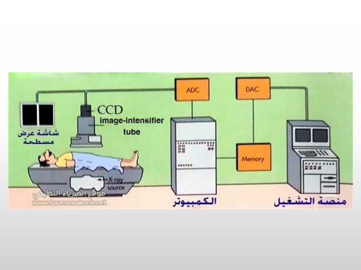
Fluoroscope Imaging Chain c. f. Bushberg, et al. The Essential Physics of Medical Imaging, 2 nd ed. , p. 232.
The Image Intensifier v. There 1. 2. 3. 4. are 4 principal components of an II: vacuum bottle to keep the air out input layer that converts the x-ray signal to electrons electronic lenses that focus the electrons output phosphor that converts the accelerated electrons into visible light
The Image Intensifier CCD TV CAMERA MIRROR ADC LENS OUTPUT PHOSPHOR APERTURE FOCUSING ELECTRODES DISPLAY ELECTRONS INPUT PHOSPHOR. . . Cs. I X-RAYS PHOTO-CATHODE LAYER
The Input Screen v The input screen of the II consists of 4 different layers: (a) vacuum window, a 1 mm aluminum window that is part of the vacuum bottle 1. keeps the air out of the II, and its curvature is designed to withstand the force of the air pressing against it a vacuum is necessary in all devices in which electrons are accelerated across open space v
The Input Screen v The input screen of the II consists of 4 different layers: (b) support layer, which is strong enough to support the input phosphor and photocathode layers, but thin enough to allow most x-rays to pass through it 0. 5 mm of aluminum, is the first component in the electronic lens system, and its curvature is designed for accurate electronic focusing v
The Input Screen v The input screen of the II consists of 4 different layers: v (c) input phosphor, whose function is to absorb the x-rays and convert their energy into visible light v cesium iodide (Cs. I) is used v long needle-like crystals which function as light pipes, channeling the visible light toward the photochathode with minimal lateral spreading v 400 mm tall, 5 mm in diameter
The Input Screen v The input screen of the II consists of 4 different layers: v (d) photocathode is a thin layer of antimony and alkali metals that emits electrons when struck by visible light v 10 to 20% conversion efficiency v 23 to 35 cm diameter input image (FOV)
Input Phosphor Energy Conversion Aluminum Support Photocathode Cs. I Needles
Input Phosphor Energy Conversion 60 ke. V X-Ray Aluminum Support Photocathode Cs. I Needles
Input Phosphor Energy Conversion Aluminum Support 3, 000 light photons = ~ 420 nm Photocathode Cs. I Needles
Input Phosphor Energy Conversion Aluminum Support Photocathode ~ 400 electrons Cs. I Needles To Anode
Electron Optics v v v Electrons are accelerated by an electric field Energy of each electron is substantially increased and this gives rise to electron gain Focusing is achieved using an electronic lens, which requires the input screen to be a curved surface, and this results in unavoidable pincushion distortion of the image
Electron Optics v v v The G 1, G 2, G 3 electrodes along with the input screen and the anode near the output phosphor comprise the fivecomponent electronic lens system of the II The electrons under the influence of the 25 K to 35 K V electric field, are accelerated and arrive at the anode with high velocity and considerable kinetic energy After penetrating the very thin anode, the energetic electrons strike the output phosphor
The Output Phosphor v v The output phosphor is made of zinc cadmium sulfide Anode is very thin coating of aluminum on the vacuum side of the output phosphor, which is electrically conductive to carry away the electrons once they deposit their energy in the phosphor Each electron causes the emission of approximately 1000 light photons from the output phosphor 2. 5 cm diameter output phosphor
The Output Phosphor v The reduction in image diameter leads to amplification (analogy: magnifying glass and sunlight) v Minification gain of an II is simply the ratio of the area of the input phosphor to that of the output phosphor, e. g. , 9’’ input phosphor, 1’ output phosphor, area is square of the radius ratio, minification gain is 81
The Output Phosphor v The output phosphor is coated right onto the output window v Some fraction of the light emitted by the output phosphor is reflected at the glass window v Light bouncing around the output window is called veiling glare, and can reduce image contrast
Image Intensifier Performance Conversion Factor = v v Light out of image intensifier (cd/m 2) Exposure rate into image intensifier (m. R/sec) Defined as a measure of the gain of an image intensifier ratio of light output to exposure rate input 100 to 200 for new image intensifier Degrades over time, ultimately can lead to II replacement
LARGE NON-MAG Fo. V e. g. , 12 INCH Magnification SMALL, MAG Fo. V e. g. , 6 INCH
Optical Coupling v Parallel rays of light enter the optical chamber, are focused by lenses, and strike the video camera where an electronic image in produced v A partially silvered mirror is used to shunt the light emitted by the image intensifier to an accessory port
Video Camera
Video Camera v Analog video systems typically have 30 frames/sec operation, but they work in an interlaced fashion to reduce flicker, the perception of the image flashing on and off v The human eye-brain system can detect temporal fluctuations slower than about 47 images/sec, and therefore at 30 frames/sec flicker would be perceptible v With interlaced systems, each frame is composed of two fields and each field is refreshed at a rate of 60 times per second, which is fast enough to avoid perception of flicker
Lag v Lag means that each new TV image actually contains residual image information from the last several frames v Lag is good and bad acts to smooth the noise in the image, but can also cause motion blurring
Lag • Effect of camera lag. Angiogram of a rapidly moving coronary artery shows a trailing "ghost" due to excessive camera lag (the direction of travel is from right to left).
Summary ü ü ü ü Fluoroscopy is a live imaging procedure Image Intensifier main component and consists of the input phosphor, electronic lens system and output phosphor Input phosphor – Cesium Iodide, converts x-rays to light Photocathode – converts light into electrons Output phosphor – Zinc cadmium sulphide, converts electrons into light Artifacts – pincushion distortion, veiling glare, lag Video camera produces the electronic image which we see on the TV monitor Use interlaced scanning to avoid flicker
Fluoroscopy Modes of Operation v Continuous fluoroscopy v continuously on x-ray beam, 0. 5 – 4 m. A or higher v display at 30 frames/sec, 33 m sec/frame v blurring present due to patient motion, acceptable v 10 R/min is the maximum legal limit v High dose rate fluoroscopy v Specially activated fluoroscopy v 20 R/min is the maximum legal limit v Audible signal required to sound v used for obese patients
Fluoroscopy Modes of Operation v Pulsed fluoro: v Series of short x-ray pulses, 30 pulses at ~10 msec per pulse v Exposure time is shorter, reduces blurring from patient motion v Can be used where object motion is high, e. g. , positioning catheters in highly pulsatile vessels v 15 frames/sec, 7. 5 frames/sec also available v Variable frame pulsed fluoroscopy is instrumental in reducing dose v Ex. , Initially guiding the catheter up from the femoral artery to the aortic arch does not require high temporal resolution and 7. 5 frames/sec could potentially be used instead of 30 frames/sec v 7. 5 frames/sec instead of 30 frames/sec, dose savings of (7. 5/30) 25%
Image Quality -Contrast Resolution v Contrast resolution is increased when higher exposure rates are used, but the disadvantage is more radiation dose to the patient v Fluoroscopic systems with different dose settings allow the user flexibility from patient to adjust the compromise between contrast resolution and patient exposure
Fluoroscopy Suites v Biplane Angiographic Systems v Two complete x-ray tube/II systems used, PA (posterior anterior) and Lateral v Simultaneous acquisition of 2 views allows a reduction of the volume of contrast media injected in patient v Portable Fluoroscopy- C Arms v C-Arm devices with an x-ray tube placed opposite from the II v 18 -cm (7 -inch) and 23 -cm (9 -inch) and several other field sizes available v Operating rooms and ICUs (An intensive care unit)
Radiation Safe Dose v Patient Dose v The maximum exposure rate permitted in the US is governed by the Code of Federal Regulations (CFR), and is overseen by the Center for Devices and Radiological Health (CDRH), a branch of the Food and Drug Administration (FDA) v Medically v The maximum legal entrance exposure rate for normal fluoroscopy to the patient is 10 R/min v For specially activated fluoroscopy, the maximum exposure rate allowable is 20 R/min
Radiation Dose v Patient Dose Typical entrance exposure rates for fluoroscopic imaging are 1. About 1 to 2 R/min for thin (10 -cm) body parts 2. 3 to 5 R/min for the average patient 3. 8 to 10 R/min for the heavy patient 1. Maximum dose at 120 k. Vp for most vendors