Fluoroscopic Unit Fluoroscopy Dynamic imaging Spot films 3


 � Ability of image intensifier tube to convert")

 � � Adjusts and maintains the overall image density and")


- Slides: 22
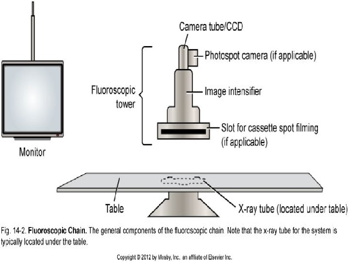
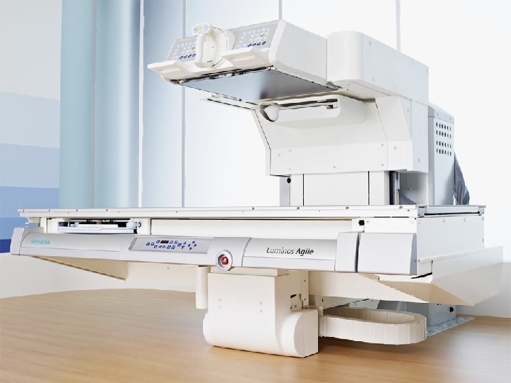
Fluoroscopic Unit
Fluoroscopy � � Dynamic imaging Spot films 3 -5 m. A k. Vp and m. A determine brightness level � Automatically adjusted during fluoro by automatic brightness control (ABC)
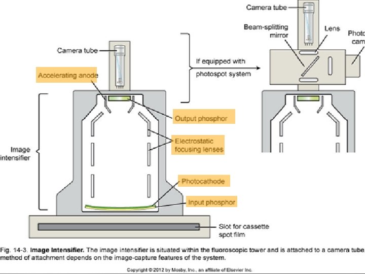
Image Intensifier � � Electronic vacuum tube Converts the remnant beam to light, then to electrons, then back to light Remnant beam-light electrons light intensity in the process Parts � Input Phosphor � Photocathode � Electrostatic focusing lenses � Accelerating anode � Output phosphor
Input Phosphor � � Made of Cesium iodide Absorbs the remnant x-ray photon energy and emits light in response Side toward the tube Side toward the patient
Photocathode � � Made of cesium and antimony compounds These metals emit electrons in response to light stimulus in a process called Photoemission
Electrostatic Focusing Lens � � Negatively charged plates along the length of the image intensifier tube Repel the electron stream, focusing it on the small output phosphor
Accelerating Anode � � Sets the electron stream in motion at a constant velocity Maintains constant potential of 25 k. V
Output Phosphor � � � Silver-activated zinc cadmium sulfide Absorbs electrons and emits light in response End result � An increase in image intensity and brightness
Magnification Mode � � Focal point is shifted farther from output phosphor Voltage to electrostatic focusing lenses is increased. The increase tightens the diameter of electron stream and focal point is shifted Increase in pt dose Spatial Resolution is improved � � Smallest structure that may be detected Measure in line pairs/mm
Magnification
Intensification Principles � Brightness gain(Conversion Factor) � Ability of image intensifier tube to convert x-ray energy into light energy & increase the brightness of the image � Minification gain x flux gain � Flux gain � Ratio of #light photons at the output phosphor to the # of light photons emitted in the input phosphor Represents the tubes conversion efficiency � Conversion factor � Luminance at output phosphor input exposure rate
� � Minification gain – the brightness gain caused from a decrease in size from the input to the output phosphor image appears brighter � Input phosphor daimeter 2 / output phosphor diameter 2
Automatic Brightness Control (ABC) � � Adjusts and maintains the overall image density and contrast during fluoroscopy Determined by the brightness control setting that the radiographer sets
Distortion � � � Misrepresentation of true size or shape of an object Caused by the curved shape of the photcathode Inaccurate control or focusing of electrons released at photocathode Pincushion appearance Vignetting-loss of brightness around the edge of the fluoroscopic image caused by the curve of the photocathode
Viewing Systems � The signal is sent to a television monitor for viewing through the Vidicon tube � Diode tube in a glass envelope � Connected to the output phosphor � Digital fluoroscopy � Computerized images from output phosphor � No need for overhead/spot films
Camera Tube
Cathode �Cathode Electron gun �Provides continuous stream of electrons Control grid �Forms the electron stream into a beam
Anode �Anode Face plate Signal plate Target