INTRODUCTION TO CRYSTAL PHYSICS What is Crystal Physics



- Slides: 187

INTRODUCTION TO CRYSTAL PHYSICS What is Crystal Physics? ‘Crystal Physics’ or ‘Crystallography’ is a branch of physics that deals with the study of all possible types of crystals and the physical properties of crystalline solids by the determination of their actual structure by using X-rays, neutron beams and electron beams. PH 0101 UNIT 4 LECTURE 1 1

CLASSIFICATION OF SOLIDS Solids can broadly be classified into two types based on the arrangement of units of matter. The units of matter may be atoms, molecules or ions. They are, Crystalline solids and Non-crystalline (or) Amorphous solids PH 0101 UNIT 4 LECTURE 1 2

CRYSTALLINE SOLIDS A substance is said to be crystalline when the arrangement of units of matter is regular and periodic. A crystalline material has directional properties and therefore called as anisotropic substance. A crystal has a sharp melting point. It possesses a regular shape and if it is broken, all broken pieces have the same regular shape. PH 0101 UNIT 4 LECTURE 1 3

CRYSTALLINE SOLIDS A crystalline material can either be a single (mono) crystal or a polycrystal. A single crystal consists of only one crystal, whereas the polycrystalline material consists of many crystals separated by well-defined boundaries. Examples Metallic crystals – Cu, Ag, Al, Mg etc, Non-metallic crystals – Carbon, Silicon, Germanium, PH 0101 UNIT 4 LECTURE 1 4

NON CRYSTALLINE SOLIDS In amorphous solids, the constituent particles are not arranged in an orderly manner. They are randomly distributed. They do not have directional properties and so they are called as `isotropic’ substances. They have wide range of melting point and do not possess a regular shape. Examples: Glass, Plastics, Rubber etc. , PH 0101 UNIT 4 LECTURE 1 5

ATOMIC ARRANGEMENT IN CRYSTALS (a) mono (or) single crystals (b) polycrystalline solids (c) amorphous solids PH 0101 UNIT 4 LECTURE 1 6

CRYSTALS It is a substance in which the constituent particles are arranged in a systematic geometrical pattern. PH 0101 UNIT 4 LECTURE 1 7

CRYSTAL STRUCTURE = Crystal structure = + Lattice PH 0101 UNIT 4 LECTURE 1 + Basis 8

UNIT CELL A unit cell is defined as a fundamental building block of a crystal structure, which can generate the complete crystal by repeating its own dimensions in various directions. PH 0101 UNIT 4 LECTURE 1 9

UNIT CELL PH 0101 UNIT 4 LECTURE 1 10

CRYSTALLOGRAPHIC AXES Consider a unit cell consisting of three mutually perpendicular edges OA, OB and OC as shown in figure. Draw parallel lines along the three edges. These lines are taken as crystallographic axes and they are denoted as X, Y and Z axes. PH 0101 UNIT 4 LECTURE 1 11

LATTICE PARAMETERS Consider the unit cell as shown in figure. Let OA, OB and OC are the intercepts made by the unit cell along X, Y and Z axes respectively. These intercepts are known as primitives. In crystallography the intercepts OA, OB and OC are represented as a , b and c. PH 0101 UNIT 4 LECTURE 1 12

LATTICE PARAMETERS The angle between X and Y axes is represented as . Similarly the angles between Y and Z and X axes are denoted by and respectively as shown in the above figure. These angles , and are called as interaxial angles or interfacial angles. To represent a lattice, the three interfacial angles and their corresponding intercepts are essential. These six parameters are said to be lattice parameters. PH 0101 UNIT 4 LECTURE 1 13

PRIMITIVE CELL It is the smallest unit cell in volume constructed by primitives. It consists of only one full atom PH 0101 UNIT 4 LECTURE 1 14

PRIMITIVE CELL A primitive cell is one, which has got the points or atoms only at the corners of the unit cell. If a unit cell consists of more than one atom, then it is not a primitive cell. Example for primitive cell : Simple Cubic unit cell. Examples for non-primitive cell: BCC and FCC unit cell. PH 0101 UNIT 4 LECTURE 1 15

CRYSTALS SYSTEMS The seven systems are, Cubic (isometric) Tetragonal Orthorhombic Trigonal (rhombohedral) Hexagonal Monoclinic and Triclinic PH 0101 UNIT 4 LECTURE 1 16

CRYSTALS SYSTEMS The space lattices formed by unit cells are marked by the following symbols. Primitive lattice: P having lattice points only at the corners of the unit cell. Body centred lattice: I having lattice points at the corners as well as at the body centre of the unit cell. PH 0101 UNIT 4 LECTURE 1 17

CRYSTALS SYSTEMS Face centred lattice: F having lattice points at the corners as well as at the face centres of the unit cell. Base centred lattice: C having lattice points at the corners as well as at the top and bottom base centres of the unit cell. PH 0101 UNIT 4 LECTURE 1 18

BRAVAIS LATTICES Bravais in 1948 showed that 14 types of unit cells under seven crystal systems are possible. They are commonly called as `Bravais lattices’. PH 0101 UNIT 4 LECTURE 1 19

PH 0101 UNIT 4 LECTURE 1 20

MILLER INDICES Miller indices is defined as the reciprocals of the intercepts made by the plane on the three axes. PH 0101 UNIT 4 LECTURE 2 21

MILLER INDICES Procedure for finding Miller Indices Step 1: Determine the intercepts of the plane along the axes X, Y and Z in terms of the lattice constants a, b and c. Step 2: Determine the reciprocals of these numbers. PH 0101 UNIT 4 LECTURE 2 22

MILLER INDICES Step 3: Find the least common denominator (lcd) and multiply each by this lcd. Step 4: The result is written in paranthesis. This is called the `Miller Indices’ of the plane in the form (h k l). PH 0101 UNIT 4 LECTURE 2 23

EXAMPLE ( 1 0 0 ) plane Plane parallel to Y and Z axes PH 0101 UNIT 4 LECTURE 2 24

MILLER INDICES IMPORTANT FEATURES OF MILLER INDICES A plane passing through the origin is defined in terms of a parallel plane having non zero intercepts. All equally spaced parallel planes have same ‘Miller indices’ i. e. The Miller indices do not only define a particular plane but also a set of parallel planes. Thus the planes whose intercepts are 1, 1, 1; 2, 2, 2; -3, -3 etc. , are all represented by the same set of Miller indices. PH 0101 UNIT 4 LECTURE 2 25

MILLER INDICES IMPORTANT FEATURES OF MILLER INDICES It is only the ratio of the indices which is important in this notation. The (6 2 2) planes are the same as (3 1 1) planes. If a plane cuts an axis on the negative side of the origin, corresponding index is negative. It is represented by a bar, like (1 0 0). i. e. Miller indices (1 0 0) indicates that the plane has an intercept in the –ve X –axis. PH 0101 UNIT 4 LECTURE 2 26

MILLER INDICES OF SOME IMPORTANT PLANES PH 0101 UNIT 4 LECTURE 2 27

CRYSTAL DIRECTIONS In crystal analysis, it is essential to indicate certain directions inside the crystal. A direction, in general may be represented in terms of three axes with reference to the origin. In crystal system, the line joining the origin and a lattice point represents the direction of the lattice point. PH 0101 UNIT 4 LECTURE 2 28

CRYSTAL DIRECTIONS To find the Miller indices of a direction, Choose a perpendicular plane to that direction. Find the Miller indices of that perpendicular plane. The perpendicular plane and the direction have the same Miller indices value. Therefore, the Miller indices of the perpendicular plane is written within a square bracket to represent the Miller indices of the direction like [ ]. PH 0101 UNIT 4 LECTURE 2 29

IMPORTANT DIRECTIONS IN CRYSTAL PH 0101 UNIT 4 LECTURE 2 30

DESIRABLE FEATURES OF MILLER INDICES The angle ‘ ’ between any two crystallographic directions [u 1 v 1 w 1] and [u 2 v 2 w 2] can be calculated easily. The angle ‘ ’ is given by, The direction [h k l] is perpendicular to the plane (h k l) PH 0101 UNIT 4 LECTURE 2 31

DESIRABLE FEATURES OF MILLER INDICES The relation between the interplanar distance and the interatomic distance is given by, for cubic crystal. If (h k l) is the Miller indices of a crystal plane then the intercepts made by the plane with the crystallographic axes are given as where a, b and c are the primitives. PH 0101 UNIT 4 LECTURE 2 32

SEPARATION BETWEEN LATTICE PLANES Consider a cubic crystal of side ‘a’, and a plane ABC. This plane belongs to a family of planes whose Miller indices are (h k l) because Miller indices represent a set of planes. Let ON =d, be the perpendicular distance of the plane A B C from the origin. PH 0101 UNIT 4 LECTURE 2 33

SEPARATION BETWEEN LATTICE PLANES PH 0101 UNIT 4 LECTURE 2 34

SEPARATION BETWEEN LATTICE PLANES Let 1, 1 and 1 (different from the interfacial angles , and ) be the angles between coordinate axes X, Y, Z and ON respectively. The intercepts of the plane on the three axes are, (1) PH 0101 UNIT 4 LECTURE 2 35

SEPARATION BETWEEN LATTICE PLANES From the figure, 4. 14(a), we have, (2) From the property of direction of cosines, (3) Using equation 1 in 2, we get, PH 0101 UNIT 4 LECTURE 2 36

SEPARATION BETWEEN LATTICE PLANES Using equation 1 in 2, we get, (4) Substituting equation (4) in (3), we get, PH 0101 UNIT 4 LECTURE 2 37

i. e. (5) i. e. the perpendicular distance between the origin and the 1 st plane ABC is, PH 0101 UNIT 4 LECTURE 2 38

Now, let us consider the next parallel plane. Let OM=d 2 be the perpendicular distance of this plane from the origin. The intercepts of this plane along the three axes are PH 0101 UNIT 4 LECTURE 2 39

SEPARATION BETWEEN LATTICE PLANES • Therefore, the interplanar spacing between two adjacent parallel planes of Miller indices (h k l ) is given by, NM = OM – ON i. e. Interplanar spacing (6) PH 0101 UNIT 4 LECTURE 2 40

CRYSTAL SYMMETRY Crystals have inherent symmetry. The definite ordered arrangement of the faces and edges of a crystal is known as `crystal symmetry’. It is a powerful tool for the study of the internal structure of crystals. Crystals possess different symmetries or symmetry elements. PH 0101 UNIT 4 LECTURE 3 41

CRYSTAL SYMMETRY What is a symmetry operation ? A `symmetry operation’ is one, that leaves the crystal and its environment invariant. It is an operation performed on an object or pattern which brings it to a position which is absolutely indistinguishable from the old position. PH 0101 UNIT 4 LECTURE 3 42

CRYSTAL SYMMETRY The seven crystal systems are characterised by three symmetry elements. They are Centre of symmetry Planes of symmetry Axes of symmetry. PH 0101 UNIT 4 LECTURE 3 43

CENTRE OF SYMMETRY It is a point such that any line drawn through it will meet the surface of the crystal at equal distances on either side. Since centre lies at equal distances from various symmetrical positions it is also known as `centre of inversions’. It is equivalent to reflection through a point. PH 0101 UNIT 4 LECTURE 3 44

CENTRE OF SYMMETRY A Crystal may possess a number of planes or axes of symmetry but it can have only one centre of symmetry. For an unit cell of cubic lattice, the point at the body centre represents’ the `centre of symmetry’ and it is shown in the figure. PH 0101 UNIT 4 LECTURE 3 45

CENTRE OF SYMMETRY PH 0101 UNIT 4 LECTURE 3 46

PLANE OF SYMMETRY A crystal is said to have a plane of symmetry, when it is divided by an imaginary plane into two halves, such that one is the mirror image of the other. In the case of a cube, there are three planes of symmetry parallel to the faces of the cube and six diagonal planes of symmetry PH 0101 UNIT 4 LECTURE 3 47

PLANE OF SYMMETRY PH 0101 UNIT 4 LECTURE 3 48

AXIS OF SYMMETRY This is an axis passing through the crystal such that if the crystal is rotated around it through some angle, the crystal remains invariant. The axis is called `n-fold, axis’ if the angle of rotation is. If equivalent configuration occurs after rotation of 180º, 120º and 90º, the axes of rotation are known as two-fold, three-fold and four-fold axes of symmetry respectively. PH 0101 UNIT 4 LECTURE 3 49

AXIS OF SYMMETRY If equivalent configuration occurs after rotation of 180º, 120º and 90º, the axes of rotation are known as twofold, three-fold and four-fold axes of symmetry. If a cube is rotated through 90º, about an axis normal to one of its faces at its mid point, it brings the cube into self coincident position. Hence during one complete rotation about this axis, i. e. , through 360º, at four positions the cube is coincident with its original position. Such an axis is called four-fold axes of symmetry or tetrad axis. PH 0101 UNIT 4 LECTURE 3 50

AXIS OF SYMMETRY If n=1, the crystal has to be rotated through an angle = 360º, about an axis to achieve self coincidence. Such an axis is called an `identity axis’. Each crystal possesses an infinite number of such axes. If n=2, the crystal has to be rotated through an angle = 180º about an axis to achieve self coincidence. Such an axis is called a `diad axis’. Since there are 12 such edges in a cube, the number of diad axes is six. PH 0101 UNIT 4 LECTURE 3 51

AXIS OF SYMMETRY If n=3, the crystal has to be rotated through an angle = 120º about an axis to achieve self coincidence. Such an axis is called is `triad axis’. In a cube, the axis passing through a solid diagonal acts as a triad axis. Since there are 4 solid diagonals in a cube, the number of triad axis is four. If n=4, for every 90º rotation, coincidence is achieved and the axis is termed `tetrad axis’. It is discussed already that a cube has `three’ tetrad axes. PH 0101 UNIT 4 LECTURE 3 52

AXIS OF SYMMETRY If n=6, the corresponding angle of rotation is 60º and the axis of rotation is called a hexad axis. A cubic crystal does not possess any hexad axis. Crystalline solids do not show 5 -fold axis of symmetry or any other symmetry axis higher than `six’, Identical repetition of an unit can take place only when we consider 1, 2, 3, 4 and 6 fold axes. PH 0101 UNIT 4 LECTURE 3 53

SYMMETRICAL AXES OF CUBE PH 0101 UNIT 4 LECTURE 3 54

SYMMETRICAL ELEMENTS OF CUBE (a) Centre of symmetry (b) Planes of symmetry (Straight planes -3, Diagonal planes -6) (c) Diad axes (d) Triad axes (e) Tetrad axes 1 9 6 4 3 ---Total number of symmetry elements = 23 ---Thus the total number of symmetry elements of a cubic structure is 23. PH 0101 UNIT 4 LECTURE 3 55

ABSENCE OF 5 FOLD SYMMETRY We have seen earlier that the crystalline solids show only 1, 2, 3, 4 and 6 -fold axes of symmetry and not 5 -fold axis of symmetry or symmetry axis higher than 6. The reason is that, a crystal is a one in which the atoms or molecules are internally arranged in a very regular and periodic fashion in a three dimensional pattern, and identical repetition of an unit cell can take place only when we consider 1, 2, 3, 4 and 6 -fold axes. PH 0101 UNIT 4 LECTURE 3 56

MATHEMATICAL VERIFICATION Let us consider a lattice P Q R S as shown in figure P Q a R a S a PH 0101 UNIT 4 LECTURE 3 57

MATHEMATICAL VERIFICATION Let this lattice has n-fold axis of symmetry and the lattice parameter be equal to ‘a’. Let us rotate the vectors Q P and R S through an angle = , in the clockwise and anti clockwise directions respectively. After rotation the ends of the vectors be at x and y. Since the lattice PQRS has n-fold axis of symmetry, the points x and y should be the lattice points. PH 0101 UNIT 4 LECTURE 3 58

MATHEMATICAL VERIFICATION Further the line xy should be parallel to the line PQRS. Therefore the distance xy must equal to some integral multiple of the lattice parameter ‘a’ say, m a. i. e. , xy = a + 2 a cos = ma (1) Here, m = 0, 1, 2, 3, . . . . From equation (1), 2 a cos = m a – a PH 0101 UNIT 4 LECTURE 3 59

MATHEMATICAL VERIFICATION i. e. , 2 a cos = a (m - 1) (or) cos = Here, (2) N = 0, 1, 2, 3, . . . since (m-1) is also an integer, say N. We can determine the values of which are allowed in a lattice by solving the equation (2) for all values of N. PH 0101 UNIT 4 LECTURE 3 60

MATHEMATICAL VERIFICATION For example, if N = 0, cos = 0 i. e. , = 90 o n = 4. In a similar way, we can get four more rotation axes in a lattice, i. e. , n = 1, n = 2, n = 3, and n = 6. Since the allowed values of cos have the limits – 1 to +1, the solutions of the equation (2) are not possible for N > 2. Therefore only 1, 2, 3, 4 and 6 fold symmetry axes can exist in a lattice. PH 0101 UNIT 4 LECTURE 3 61

ROTATION AXES ALLOWED IN A LATTICE cos (degrees) n= N N/2 -2 -1 -1 180 2 -1 -1/2 120 3 0 0 0 90 4 +1 +1/2 60 6 +2 +1 +1 360 (or) 0 1 PH 0101 UNIT 4 LECTURE 3 62

ROTO INVERSION AXES Rotation inversion axis is a symmetry element which has a compound operation of a proper rotation and an inversion. A crystal structure is said to possess a rotation – inversion axis if it is brought into self coincidence by rotation followed by an inversion about a lattice point through which the rotation axis passes. PH 0101 UNIT 4 LECTURE 3 63

ROTO INVERSION AXES X 3 2 4 1 X 1 PH 0101 UNIT 4 LECTURE 3 64

ROTO INVERSION AXES Let us consider an axis xx , normal to the circle passing through the centre. Let it operates on a point (1) to rotate it through 90 o to the position (4) followed by inversion to the position (2), this compound operation is then repeated until the original position is again reached. PH 0101 UNIT 4 LECTURE 3 65

ROTO INVERSION AXES Thus, from position (2), the point is rotated a further 90 o and inverted to the position (3); from position (3), the point is rotated a further 90 o and inverted to a position (4); from position (4), the point is rotated a further 90 o and inverted to resume position (1). Thus if we do this compound operation about a point four times, it will get the original position. This is an example for 4 -fold roto inversion axis. Crystals possess 1, 2, 3, 4 and 6 -fold rotation inversion axes. PH 0101 UNIT 4 LECTURE 3 66

TRANSLATIONAL SYMMETRY SCREW AXES This symmetry element has a compound operation of a proper rotation with a translation parallel to the rotation axis This is shown in the figure. In this operation, a rotation takes place from A to B by an amount of and it combines with a translation from B to C by an amount of T, which is equivalent to a screw motion from A to C. The symmetry element that corresponds to such a motion is called a screw axis. PH 0101 UNIT 4 LECTURE 3 67

TRANSLATIONAL SYMMETRY SCREW AXES C T A θ PH 0101 UNIT 4 LECTURE 3 B 68

TRANSLATIONAL SYMMETRY GLIDE PLANE This symmetry element also has a compound operation of a reflection with a translation parallel to the reflection plane. Figure shows the operation of a glide plane If the upper layer of atoms is moved through a distance of a/2, and then reflected in the plane mm 1, the lower plane of atoms is generated. PH 0101 UNIT 4 LECTURE 3 69

TRANSLATIONAL SYMMETRY GLIDE PLANE a m m 1 a/2 PH 0101 UNIT 4 LECTURE 3 70

COMBINATION OF SYMMETRY ELEMENTS Apart from the different symmetry elements different combinations of the basic symmetry elements are also possible. They give rise to different symmetry points in the crystal. The combination of symmetry elements at a point is called a `point group’. PH 0101 UNIT 4 LECTURE 3 71

COMBINATION OF SYMMETRY ELEMENTS In crystals, 32 point groups are possible. The combination of 32 point groups with 14 Bravais lattices lead to 230 unique arrangements of points in space. They are called as `space groups’. PH 0101 UNIT 4 LECTURE 3 72

RECIPROCAL LATTICE The concept of ‘reciprocal lattice’ provides a device for tabulating both the slopes and the interplanar spacings of the planes of a crystal lattice. In a crystal, there exist many sets of planes with different orientations and spacing. These planes can cause diffraction. If we draw normals to all sets of planes, from a common origin, then the end points of normals form a lattice which is called as ‘reciprocal lattice’. PH 0101 UNIT 4 LECTURE 4 73

FORMATION OF RECIPROCAL LATTICE PH 0101 UNIT 4 LECTURE 4 74

CRYSTAL STRUCTURE OF MATERIALS NUMBER OF ATOMS PER UNIT CELL (n) The total number of atoms present in an unit cell is known as number of atoms per unit cell. COORDINATION NUMBER (CN) It is the number of nearest neighboring atoms to a particular atom. ATOMIC RADIUS (r) It is the radius of an atom. It is also defined as half the distance between two nearest neighboring atoms in a crystal. PH 0101 UNIT 4 LECTURE 4 75

CRYSTAL STRUCTURE OF MATERIALS ATOMIC PACKING FACTOR (APF) It is the ratio of volume occupied by the atoms or molecules in an unit cell (v) to the total volume of the unit cell (V). APF = No. of atoms present in the unit cell x Volume of the atom Volume of the unit cell PH 0101 UNIT 4 LECTURE 4 76

SIMPLE CUBIC STRUCTURE PH 0101 UNIT 4 LECTURE 4 77

SIMPLE CUBIC STRUCTURE Each and every corner atom is shared by eight adjacent unit cells. The contribution of each and every corner atom to one unit cell is 1/8. The total number of atoms present in a unit cell =1/8 x 8 =1. CORDINATION NUMBER (CN) For SCC atom, there are four nearest neighbours in its own plane. There is another nearest neighbour in a plane which lies just above this atom and yet another nearest neighbour in another plane which lies just below this atom. Therefore the co-ordination number is 6. PH 0101 UNIT 4 LECTURE 4 78

SIMPLE CUBIC STRUCTURE a ATOMIC RADIUS (R) Since the atoms touch along cube edges, the atomic radius for simple cubic unit cell is, r = (where a = 2 r, is the lattice constant) ATOMIC PACKING FACTOR (APF) APF = v = 1 4/3 r 3 PH 0101 UNIT 4 LECTURE 4 79

SIMPLE CUBIC STRUCTURE V = a 3 APF = Substituting r = , we get, APF = PH 0101 UNIT 4 LECTURE 4 80

SIMPLE CUBIC STRUCTURE Therefore packing density = /6 = 0. 5236 APF = 0. 52 Thus 52 percent of the volume of the simple cubic unit cell is occupied by atoms and the remaining 48 percent volume of the unit cell is vacant or void space. PH 0101 UNIT 4 LECTURE 4 81

BODY CENTERED CUBIC STRUCTURE A body centred cubic structure has eight comer atoms and one body centred atom. The atom at the centre touches all the eight corner atoms. The BCC structure is shown in the figure. PH 0101 UNIT 4 LECTURE 4 82

BODY CENTERED CUBIC STRUCTURE PH 0101 UNIT 4 LECTURE 4 83

BODY CENTERED CUBIC STRUCTURE PH 0101 UNIT 4 LECTURE 4 84

BODY CENTERED CUBIC STRUCTURE In BCC unit cell, each and every corner atom is shared by eight adjacent unit cells. is So, the total number of atoms contributed by the corner atoms × 8 = 1. A BCC unit cell has one full atom at the centre of the unit cell. The total number of atoms present in a BCC unit cell = 1+1 = 2. PH 0101 UNIT 4 LECTURE 4 85

BODY CENTERED CUBIC STRUCTURE a CO-ORDINATION NUMBER (CN) Let us consider a body centred atom. The nearest neighbour for body centred atom is a corner atom. A body centred atom is surrounded by eight corner atoms. Therefore, the co-ordination number of a BCC unit cell = 8. ATOMIC RADIUS (R) For a BCC unit cell, the atomic radius can be calculated From figure AB = BC = AD =PH‘a’ and CD = 4 r. 0101 UNIT 4 LECTURE 4 86

BODY CENTERED CUBIC STRUCTURE From the triangle, ACD, CD 2 = AC 2 + AD 2 CD 2 = 2 a 2 + a 2 (4 r)2 = 3 a 2 16 r 2 = 3 a 2 i. e. r 2 = PH 0101 UNIT 4 LECTURE 4 87

BODY CENTERED CUBIC STRUCTURE atomic radius r = a ATOMIC PACKING FACTOR (APF) APF = The number of atoms present in an unit cell = 2 v = 2 x 4/3 r 3 V = a 3 PH 0101 UNIT 4 LECTURE 4 88

BODY CENTERED CUBIC STRUCTURE APF = Substituting r = we get APF = = 0. 68 PH 0101 UNIT 4 LECTURE 4 89

BODY CENTERED CUBIC STRUCTURE Thus 68 percent of the volume of the BCC unit cell is occupied by atoms and the remaining 32 percent volume of the unit cell is vacant or void space. PH 0101 UNIT 4 LECTURE 4 90

FACE CENTERED CUBIC STRUCTURE PH 0101, UNIT 4, LECTURE 5 91

FACE CENTERED CUBIC STRUCTURE PH 0101, UNIT 4, LECTURE 5 92

FACE CENTERED CUBIC STRUCTURE The atoms in a FCC unit cell touches along the face diagonal. Each and every corner atom is shared by eight adjacent unit cells. Therefore each and every corner atom contributes 1/8 of its part to one unit cell. So the total number of atoms contributed by the corner atoms is 8 = 1. PH 0101, UNIT 4, LECTURE 5 93

FACE CENTERED CUBIC STRUCTURE Two unit cells share each and every face centered atom. Therefore, the contribution of a face centered atom to unit cell is 1/2. So, the total number of atoms contributed by the face centred atoms = 1/2 6 = 3. The total number of atoms present in a FCC unit cell = 1+3 = 4. PH 0101, UNIT 4, LECTURE 5 94

FACE CENTERED CUBIC STRUCTURE COORDINATION NUMBER In its own plane it touches four face centered atoms. The face centered atoms are its nearest neighbors. In a plane, which lies just above this corner atom, it has four more face centered atoms as nearest neighbors. Similarly, in a plane, which lies just below this corner atom it has yet four more face centered atoms as its nearest neighbors. PH 0101, UNIT 4, LECTURE 5 95

FACE CENTERED CUBIC STRUCTURE Therefore the number of nearest neighbours i. e. , co-ordination number for FCC unit cell = 4+4+4 = 12 ATOMIC RADIUS (R) Consider the figure 4. 25(c) From the figure, AB = AC = ‘a’ and AC = 4 r. From the triangle ABC, AC 2 = AB 2 + BC 2 AC 2 = a 2 + a 2 PH 0101, UNIT 4, LECTURE 5 96

FACE CENTERED CUBIC STRUCTURE AC 2 = 2 a 2 AC = i. e. 4 r = Therefore atomic radius = ATOMIC PACKING FACTOR (APF) APF = PH 0101, UNIT 4, LECTURE 5 97

FACE CENTERED CUBIC STRUCTURE v = 4 r 3 V = a 3 APF = Substituting r = , we get, APF = PH 0101, UNIT 4, LECTURE 5 98

FACE CENTERED CUBIC STRUCTURE APF = = 0. 74 Thus 74 percent of the volume of the FCC unit cell is occupied by atoms and the remaining 26 percent volume of the unit cell is vacant or void space. PH 0101, UNIT 4, LECTURE 5 99

HEXAGONAL CLOSED PACKED STRUCTURE PH 0101, UNIT 4, LECTURE 5 100

HEXAGONAL CLOSED PACKED STRUCTURE It consists of three layers of atoms. The bottom layer has six corner atoms and one face centred atom. The middle layer has three full atoms. The upper layer has six corner atoms and one face centred atom. Each and every corner atom contributes 1/6 of its part to one unit cell. The number of total atoms contributed by the corner atoms of both top and bottom layers is 1/6 12 = 2. PH 0101, UNIT 4, LECTURE 5 101

HEXAGONAL CLOSED PACKED STRUCTURE The face centred atom contributes 1/2 of its part to one unit cell. Since there are 2 face centred atoms, one in the top and the other in the bottom layers, the number of atoms contributed by face centred atoms is 1/2 2 = 1. Besides these atoms, there are 3 full atoms in the middle layer. Total number of atoms present in an HCP unit cell is 2+1+3 = 6. PH 0101, UNIT 4, LECTURE 5 102

HEXAGONAL CLOSED PACKED STRUCTURE CO-ORDINATION NUMBER (CN) The face centered atom touches 6 corner atoms in its plane. The middle layer has 3 atoms. There are three more atoms, which are in the middle layer of the unit cell. Therefore the total number of nearest neighbours is 6+3+3=12. PH 0101, UNIT 4, LECTURE 5 103

HEXAGONAL CLOSED PACKED STRUCTURE ATOMIC RADIUS (R) Consider any two corner atoms. Each and every corner atom touches each other. Therefore a = 2 r. i. e. , The atomic radius, r = a/2 PH 0101, UNIT 4, LECTURE 5 104

HEXAGONAL CLOSED PACKED STRUCTURE a a PH 0101, UNIT 4, LECTURE 5 105

HEXAGONAL CLOSED PACKED STRUCTURE ATOMIC PACKING FACTOR (APF) APF = v = 6 4/3 r 3 Substitute r = , v = 6 4/3 v = a 3 PH 0101, UNIT 4, LECTURE 5 106

HEXAGONAL CLOSED PACKED STRUCTURE PH 0101, UNIT 4, LECTURE 5 107

HEXAGONAL CLOSED PACKED STRUCTURE AB = AC = BO = ‘a’. CX = where c height of the hcp unit cell. Area of the base = 6 area of the triangle – ABO = 6 1/2 AB OO Area of the base = 6 1/2 a OO In triangle OBO PH 0101, UNIT 4, LECTURE 5 108

HEXAGONAL CLOSED PACKED STRUCTURE cos 30º = OO = a cos 30º = a Now, substituting the value of OO , Area of the base = 6 a a = V = Area of the base × height PH 0101, UNIT 4, LECTURE 5 109

HEXAGONAL CLOSED PACKED STRUCTURE V= c APF = = APF = PH 0101, UNIT 4, LECTURE 5 110

CALCULATION OF c/a RATIO In the triangle ABA , Cos 30º = AA = AB cos 30º = a But AX = AA = i. e. AX = PH 0101, UNIT 4, LECTURE 5 111

CALCULATION OF c/a RATIO In the triangle AXC, AC 2 = AX 2 + CX 2 Substituting the values of AC, AX and CX, a 2 = PH 0101, UNIT 4, LECTURE 5 112

CALCULATION OF c/a RATIO Now substituting the value of to calculate APF of an hcp unit cell, PH 0101, UNIT 4, LECTURE 5 113

HEXAGONAL CLOSED PACKED STRUCTURE APF = = APF = Packing Fraction =74% PH 0101, UNIT 4, LECTURE 5 114

RELATION BETWEEN LATTICE CONSTANT AND DENSITY Consider a cubic crystal of lattice constant ‘a’. Density of the crystal = ρ Volume of the unit cell = V = a 3 Number of atoms per unit cell = n Atomic weight of the material = M Avagadro number N = PH 0101 UNIT 4 LECTURE 6 115

RELATION BETWEEN LATTICE CONSTANT AND DENSITY In M gram of material there are ‘N’ atoms i. e. , mass of N atoms is ‘M’ gram. Mass of 1 atom = Mass of ‘n’ molecules i. e. , mass of an unit cell = (1) Density ‘ρ’= i. e. ρ = PH 0101 UNIT 4 LECTURE 6 116

RELATION BETWEEN LATTICE CONSTANT AND DENSITY ρ= mass ‘m’ = ρ a 3 (2) Equating (1) and (2), we get, ρ a 3 = ρ = PH 0101 UNIT 4 LECTURE 6 117

RELATION BETWEEN LATTICE CONSTANT AND DENSITY ρ = PH 0101 UNIT 4 LECTURE 6 118

DIAMOND CUBIC STRUCTURE It is formed by carbon atoms. Every carbon atom is surrounded by four other carbon atoms situated at the corners of regular tetrahedral by the covalent linkages. The diamond cubic structure is a combination of two interpenetrating FCC sub lattices displaced along the body diagonal of the cubic cell by 1/4 th length of that diagonal. Thus the origins of two FCC sub lattices lie at (0, 0, 0) and (1/4, 1/4) PH 0101 UNIT 4 LECTURE 6 119

DIAMOND CUBIC STRUCTURE a Z 2 r a/4 X Y a/4 W a/4 PH 0101 UNIT 4 LECTURE 6 120

DIAMOND CUBIC STRUCTURE The points at 0 and 1/2 are on the FCC lattice, those at 1/4 and 3/4 are on a similar FCC lattice displaced along the body diagonal by one-fourth of its length. In the diamond cubic unit cell, there are eight corner atoms, six face centred atoms and four more atoms. No. of atoms contributed by the corner atoms to an unit cell is 1/8× 8 =1. No. of atoms contributed by the face centred atoms to the unit cell is 1/2 × 6 = 3 There are four more atoms inside the structure. PH 0101 UNIT 4 LECTURE 6 121

DIAMOND CUBIC STRUCTURE No. of atoms present in a diamond cubic unit cell is 1 + 3 + 4 = 8. Since each carbon atom is surrounded by four more carbon atoms, the co-ordination number is 4. ATOMIC RADIUS(R) From the figure, in the triangle WXY, XY 2 = XW 2 + WY 2 = PH 0101 UNIT 4 LECTURE 6 122

DIAMOND CUBIC STRUCTURE XY 2 = Also in the triangle XYZ, XZ 2 = XY 2 + YZ 2 = XZ 2 = PH 0101 UNIT 4 LECTURE 6 123

DIAMOND CUBIC STRUCTURE But XZ = 2 r (2 r)2 = 4 r 2 = r 2= Atomic radius r = PH 0101 UNIT 4 LECTURE 6 124

DIAMOND CUBIC STRUCTURE Atomic packing factor (APF) APF = v = i. e. v = APF = PH 0101 UNIT 4 LECTURE 6 125

DIAMOND CUBIC STRUCTURE APF = i. e. APF = 34% Thus it is a loosely packed structure. PH 0101 UNIT 4 LECTURE 6 126

Crystal Defects

Is a lattice finite or infinite? Is a crystal finite or infinite? Free surface: a 2 D defect

Vacancy: A point defect

Defects Dimensionality Examples Point 0 Vacancy Line 1 Dislocation Surface 2 Free surface, Grain boundary

Point Defects Vacancy

Point Defects: vacancy Fact There may be vacant sites in a crystal Surprising Fact There must be a certain fraction of vacant sites in a crystal in equilibrium.

Vacancy • Crystal in equilibrium • Minimum Gibbs free energy G at constant T and P • A certain concentration of vacancy lowers the free energy of a crystal

Vacancy increases H of the crystal due to energy required to break bonds D H = n D Hf

Point Defects Interstitial impurity vacancy Substitutional impurity

Defects in ionic solids Frenkel defect Cation vacancy + cation interstitial Schottky defect Cation vacancy + anion vacancy

Line Defects Dislocations

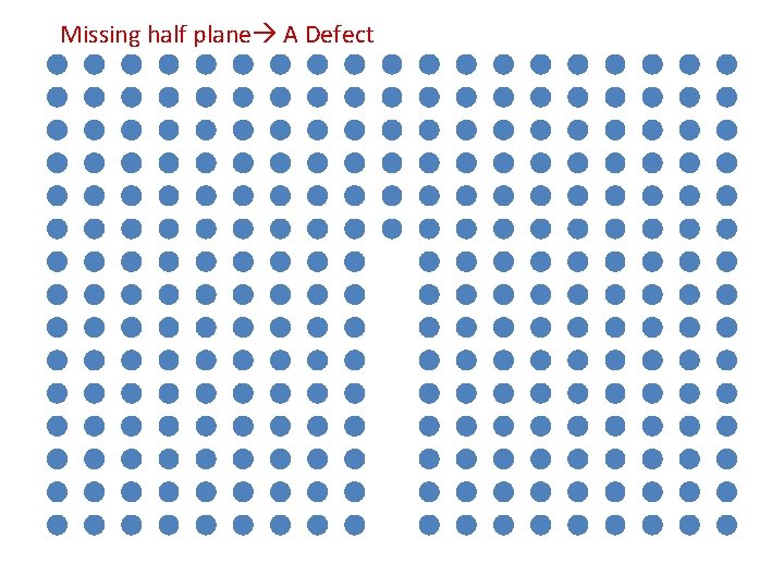
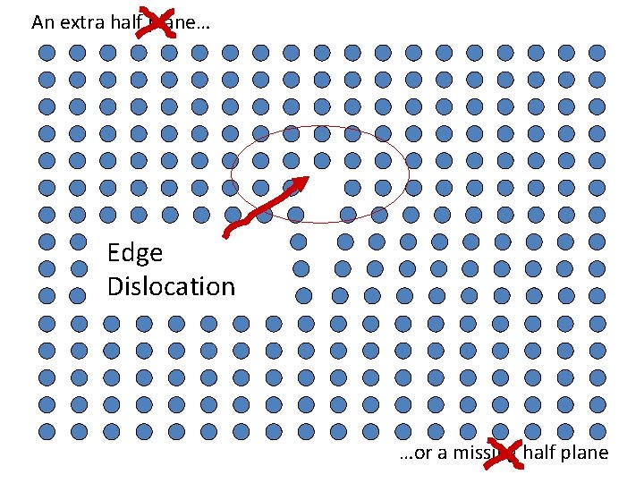
Missing half plane A Defect

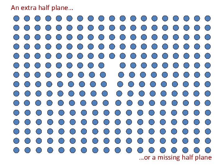
An extra half plane… …or a missing half plane

What kind of defect is this? A line defect? Or a planar defect?

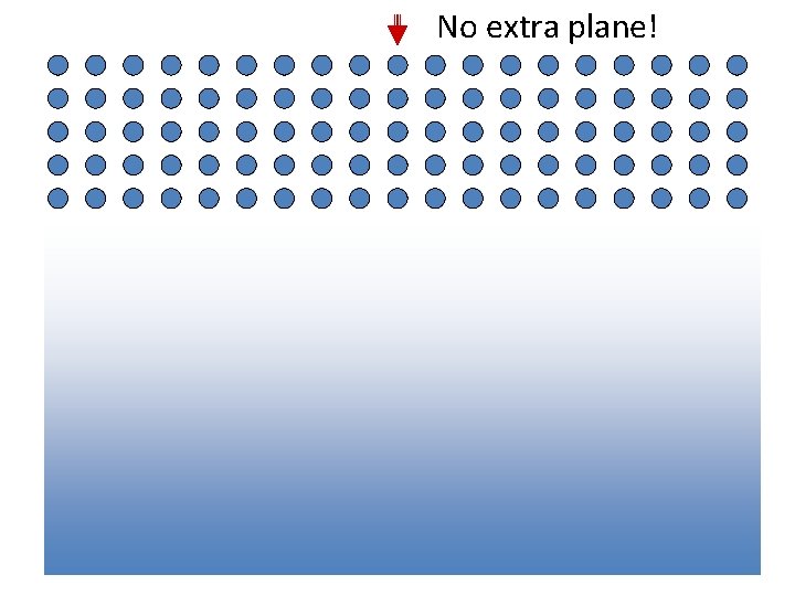
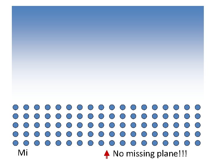
Extra half plane No extra plane!

Missing plane No missing plane!!!

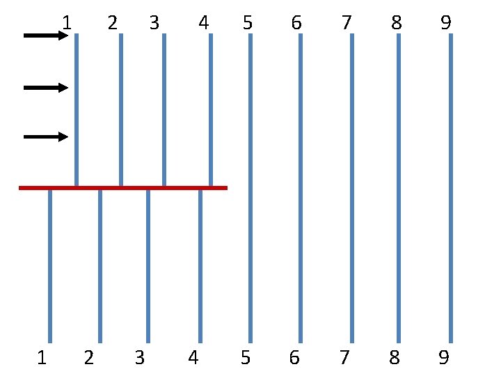
An extra half plane… Edge Dislocation …or a missing half plane

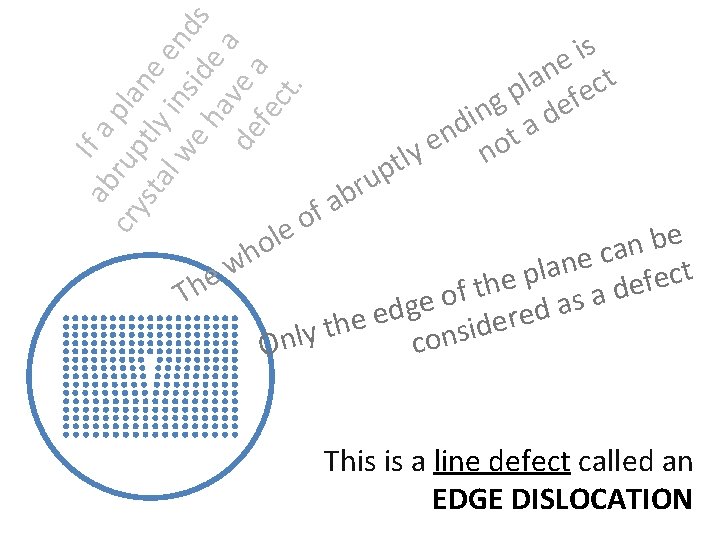
ab If a cry rup pla sta tly ne l w in en e h side ds av a de e a fe ct. le o h p u r b s i e t n la fec p g de n i d ta n e y no lt a f o e b n a c e n w a l t p c e e e f h e t d f Th a o s e a g d d e e r e e h d t i s y l n n o c O This is a line defect called an EDGE DISLOCATION

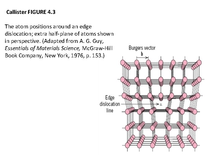
Callister FIGURE 4. 3 The atom positions around an edge dislocation; extra half-plane of atoms shown in perspective. (Adapted from A. G. Guy, Essentials of Materials Science, Mc. Graw-Hill Book Company, New York, 1976, p. 153. )

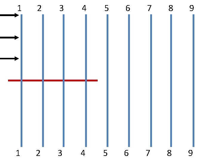
1 2 3 4 5 6 7 8 9

1 1 2 2 3 3 4 4 5 6 7 8 9

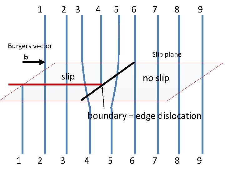
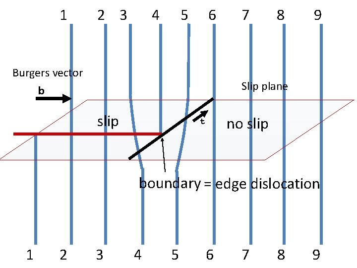
1 2 3 4 5 6 Burgers vector b 7 8 9 Slip plane slip no slip boundary = edge dislocation 1 2 3 4 5 6 7 8 9

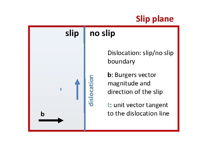
Slip plane slip no slip t b dislocation Dislocation: slip/no slip boundary b: Burgers vector magnitude and direction of the slip t: unit vector tangent to the dislocation line

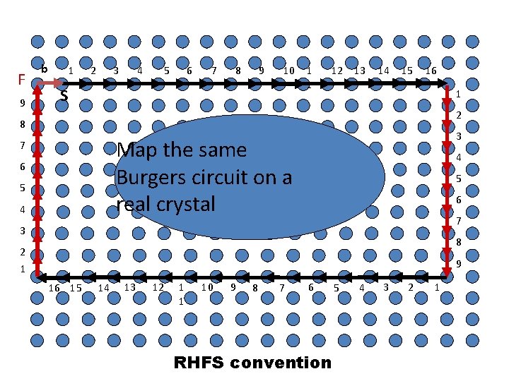
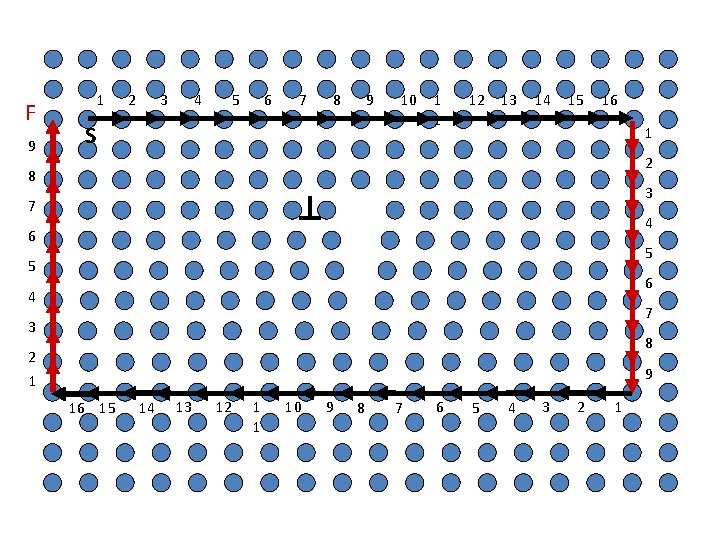
Dislocation Line: A dislocation line is the boundary between slip and no slip regions of a crystal Burgers vector: The magnitude and the direction of the slip is represented by a vector b called the Burgers vector, Line vector A unit vector t tangent to the dislocation line is called a tangent vector or the line vector.

1 2 3 4 5 6 Burgers vector b 7 8 9 Slip plane slip no slip t boundary = edge dislocation 1 2 3 4 5 6 7 8 9

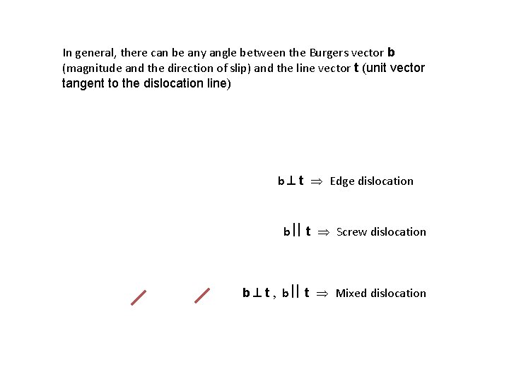
In general, there can be any angle between the Burgers vector b (magnitude and the direction of slip) and the line vector t (unit vector tangent to the dislocation line) b t Edge dislocation b t Screw dislocation b t , b t Mixed dislocation

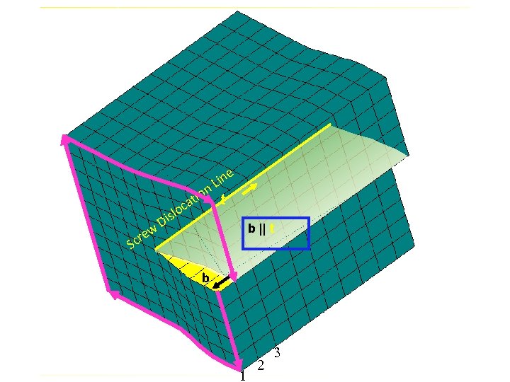
e in L on t i t ca w cre lo s i D b || t S b 1 2 3

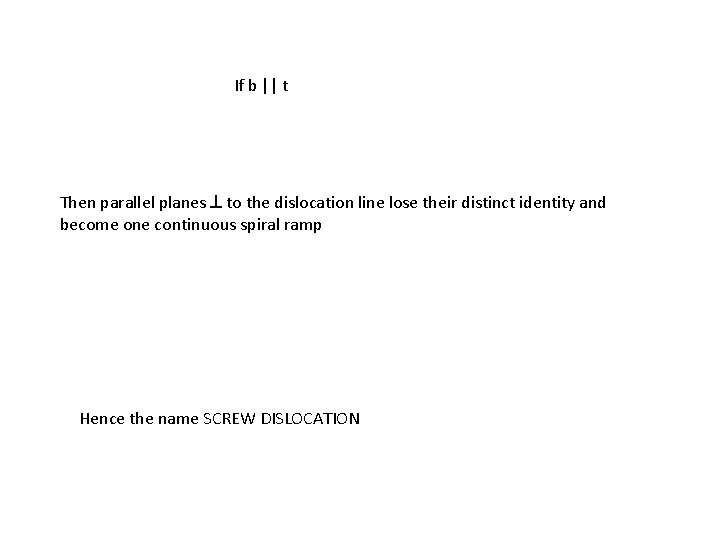
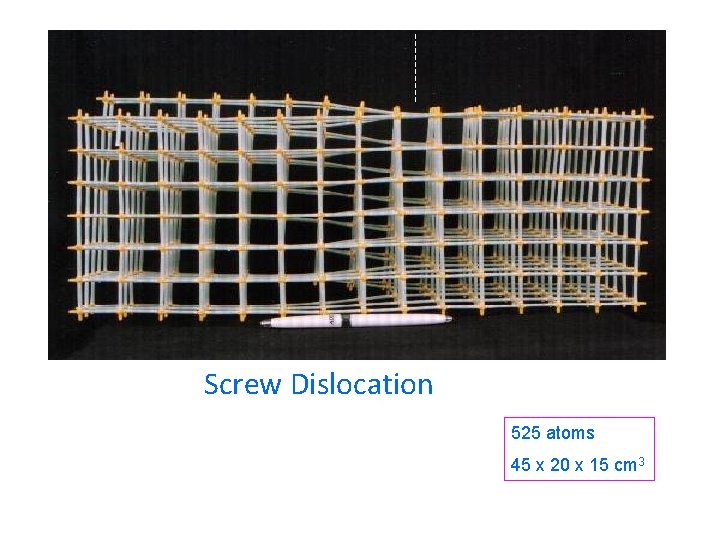
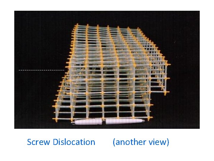
If b || t Then parallel planes to the dislocation line lose their distinct identity and become one continuous spiral ramp Hence the name SCREW DISLOCATION

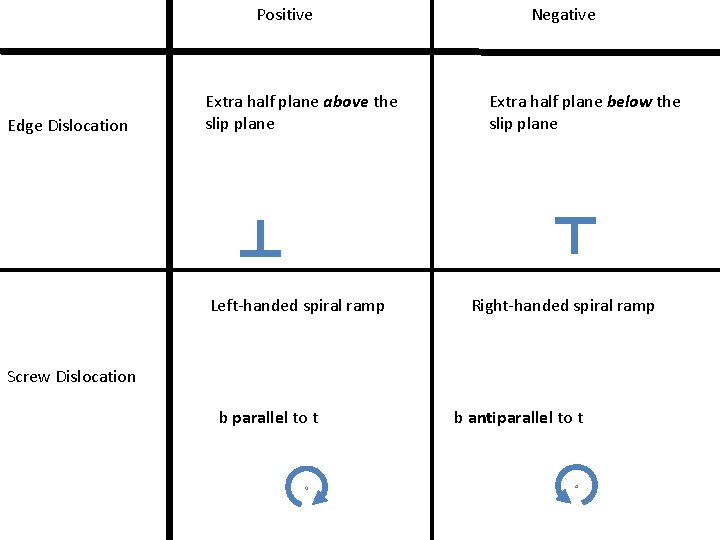
Positive Edge Dislocation Extra half plane above the slip plane Left-handed spiral ramp Negative Extra half plane below the slip plane Right-handed spiral ramp Screw Dislocation b parallel to t b antiparallel to t

Burgers vector Johannes Martinus BURGERS Burger’s vector Burgers vector

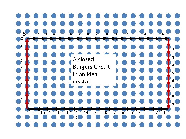
S F 1 2 3 4 5 6 7 8 9 10 1 1 12 13 14 15 16 1 9 2 8 3 A closed Burgers Circuit in an ideal crystal 7 6 5 4 4 5 6 7 3 8 2 1 9 16 15 14 13 12 1 1 10 9 8 7 6 5 4 3 2 1

F 9 b 1 2 4 3 5 6 7 8 9 10 S 1 1 12 13 14 15 16 1 2 8 3 Map the same Burgers circuit on a real crystal 7 6 5 4 4 5 6 7 3 8 2 1 9 16 15 14 13 12 1 1 10 9 8 7 6 RHFS convention 5 4 3 2 1

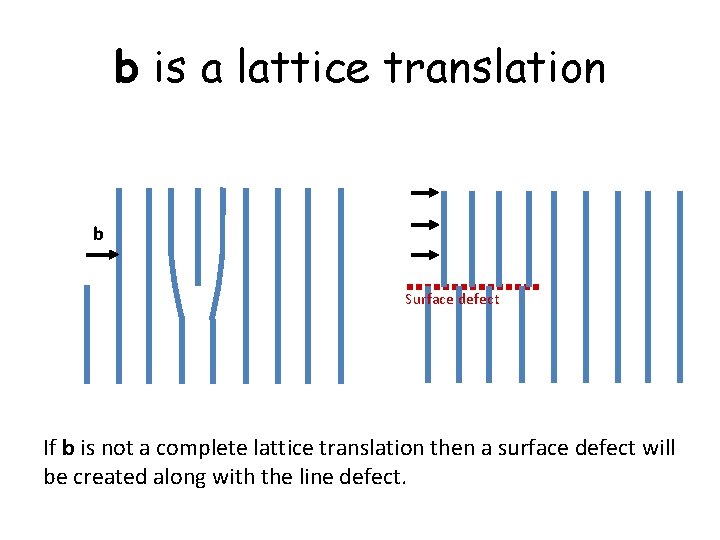
b is a lattice translation b Surface defect If b is not a complete lattice translation then a surface defect will be created along with the line defect.

F 9 1 2 4 3 5 6 7 8 9 10 S 1 1 12 13 14 15 16 1 2 8 3 7 6 4 5 5 6 4 7 3 8 2 1 9 16 15 14 13 12 1 1 10 9 8 7 6 5 4 3 2 1

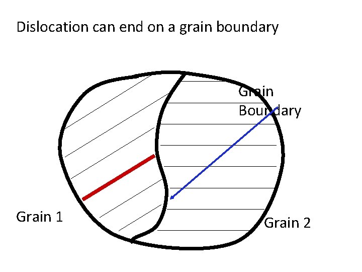
Dislocation can end on a grain boundary Grain Boundary Grain 1 Grain 2

Surface Defects

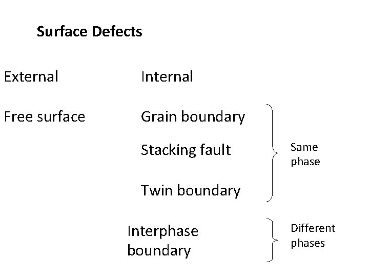
Surface Defects External Internal Free surface Grain boundary Stacking fault Same phase Twin boundary Interphase boundary Different phases

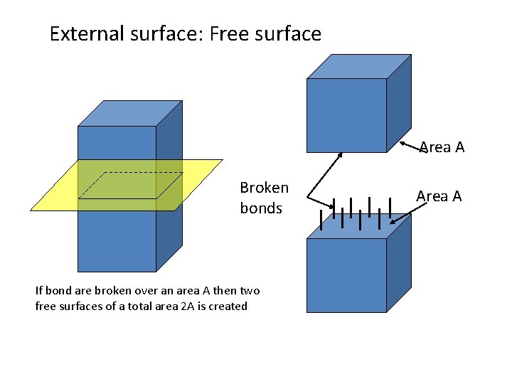
External surface: Free surface Area A Broken bonds If bond are broken over an area A then two free surfaces of a total area 2 A is created Area A

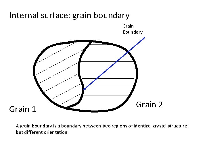
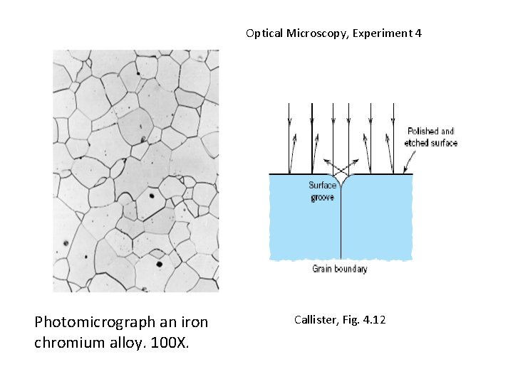
Internal surface: grain boundary Grain Boundary Grain 1 Grain 2 A grain boundary is a boundary between two regions of identical crystal structure but different orientation

Optical Microscopy, Experiment 4 Photomicrograph an iron chromium alloy. 100 X. Callister, Fig. 4. 12

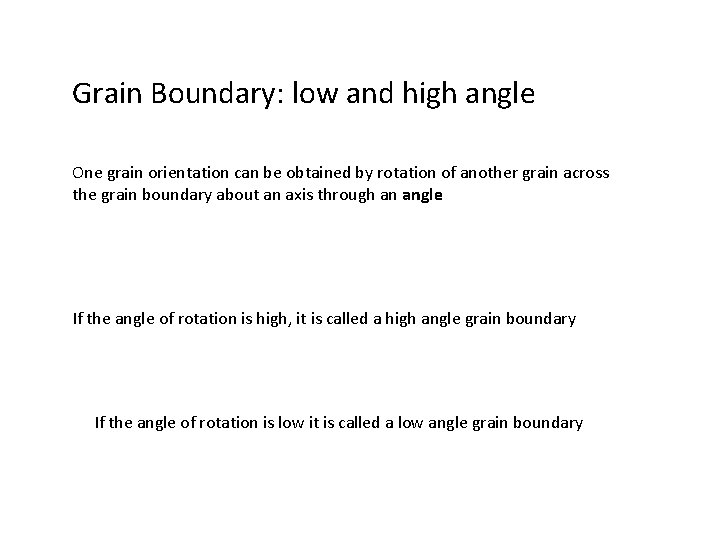
Grain Boundary: low and high angle One grain orientation can be obtained by rotation of another grain across the grain boundary about an axis through an angle If the angle of rotation is high, it is called a high angle grain boundary If the angle of rotation is low it is called a low angle grain boundary

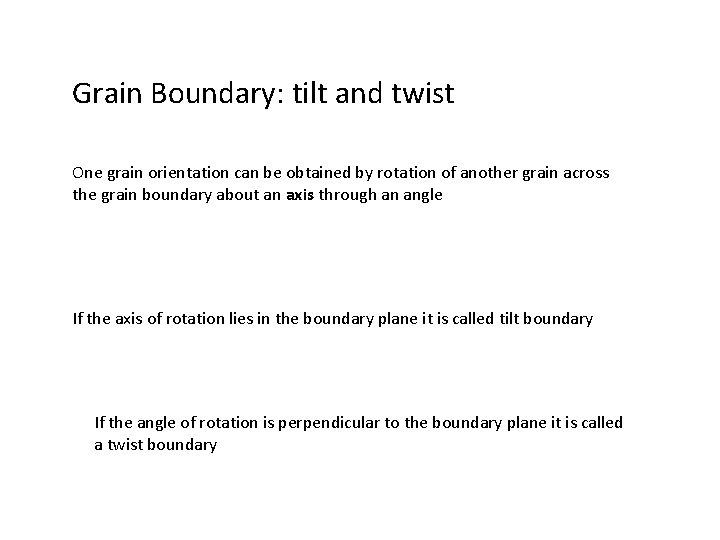
Grain Boundary: tilt and twist One grain orientation can be obtained by rotation of another grain across the grain boundary about an axis through an angle If the axis of rotation lies in the boundary plane it is called tilt boundary If the angle of rotation is perpendicular to the boundary plane it is called a twist boundary

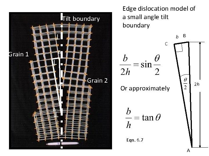
Tilt boundary Edge dislocation model of a small angle tilt boundary b B Grain 1 C C B Grain 2 2 h Or approximately A Eqn. 6. 7 A

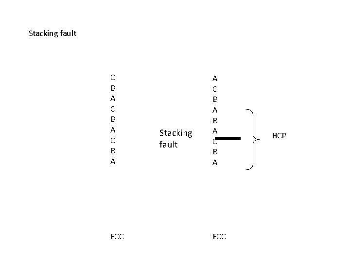
Stacking fault C B A FCC Stacking fault A C B A FCC HCP

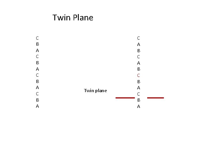
Twin Plane C B A Twin plane C A B C B A

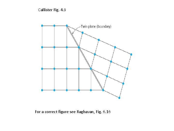
Callister Fig. 4. 9 For a correct figure see Raghavan, Fig. 6. 16

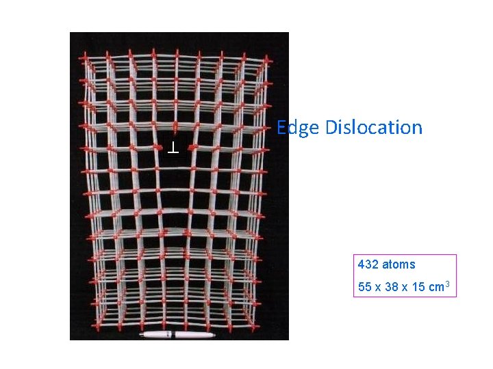
Edge Dislocation 432 atoms 55 x 38 x 15 cm 3

Screw Dislocation 525 atoms 45 x 20 x 15 cm 3

Screw Dislocation (another view)

v A dislocation cannot end abruptly inside a crystal v Burgers vector of a dislocation is constant

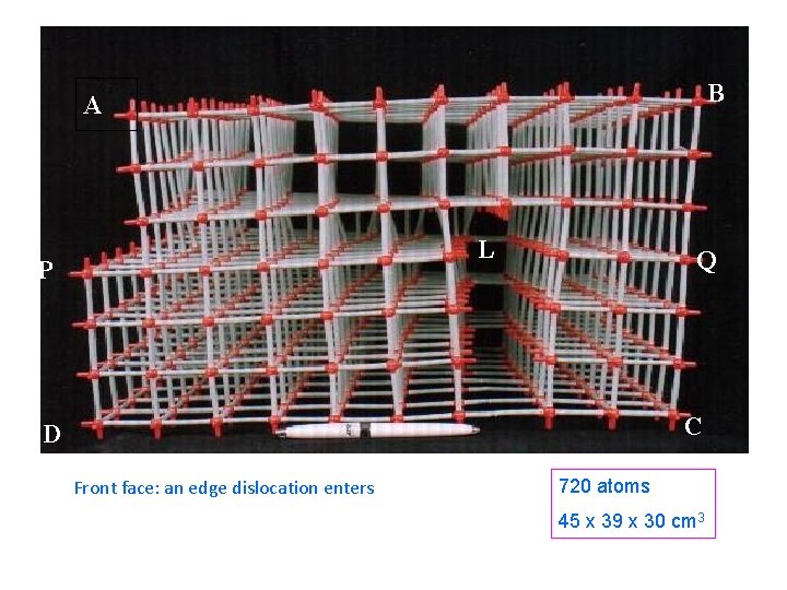
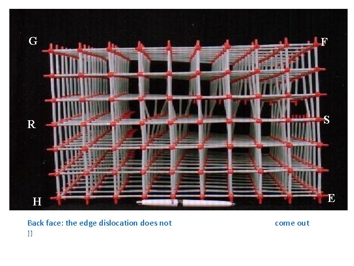
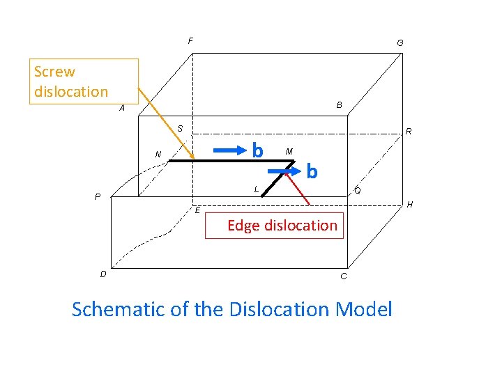
B A L P Q C D Front face: an edge dislocation enters 720 atoms 45 x 39 x 30 cm 3

G F R S E H Back face: the edge dislocation does not !! come out

F G Screw dislocation B A S b N M b L P E D R Q H Edge dislocation C Schematic of the Dislocation Model

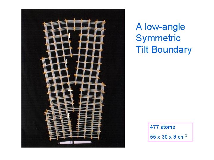
A low-angle Symmetric Tilt Boundary 477 atoms 55 x 30 x 8 cm 3

R. Prasad Dislocation Models for Classroom Demonstrations Conference on Perspectives in Physical Metallurgy and Materials Science Indian Institute of Science, Bangalore 2001

MODELS OF DISLOCATIONS FOR CLASSROOM*** R. Prasad Journal of Materials Education Vol. 25 (4 -6): 113 - 118 (2003) International Council of Materials Education Editors: John E. E. Baglin , IBM Prof. James A. Clum, Univ. of Wisconsin

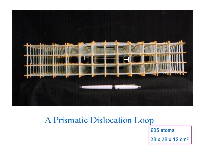
A Prismatic Dislocation Loop 685 atoms 38 x 12 cm 3

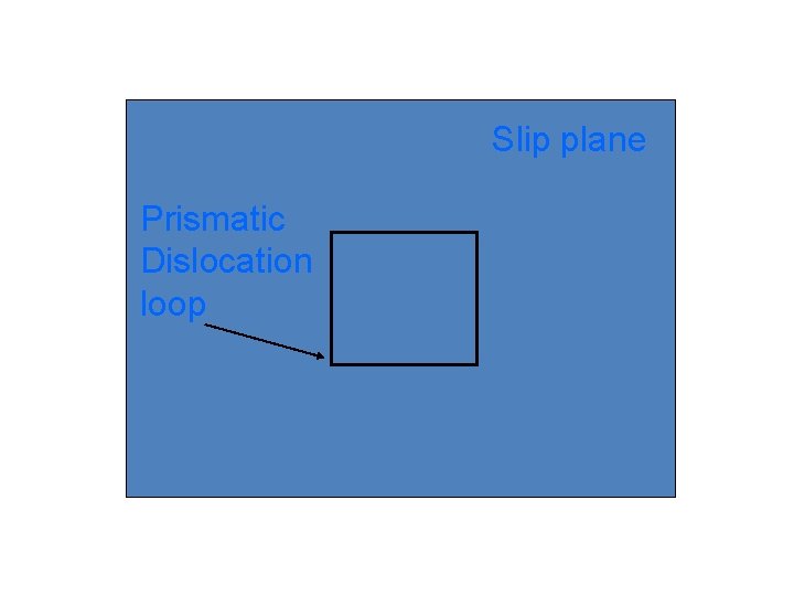
Slip plane Prismatic Dislocation loop

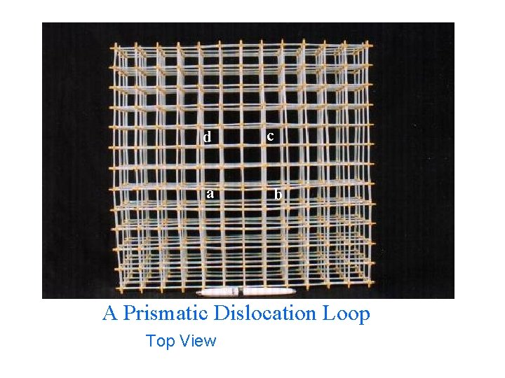
d a c b A Prismatic Dislocation Loop Top View

Welcome to Cochranes Manufacturers and suppliers of quality, affordable educational equipment, toys and Kites since 1962. Our reputation is based on innovation, quality and value. Please select a zone to continue. . . Science & Education | Kites | Birdscaring | Promotions & Incentives. All material copyright Cochranes of Oxford Ltd. Tel: +44 (0)1993 832868. Fax: +44 (0)1993 832578. Email cochranes@mailbox. co. uk

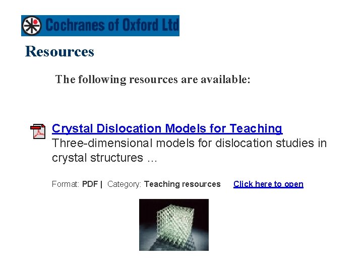
Resources The following resources are available: Crystal Dislocation Models for Teaching Three-dimensional models for dislocation studies in crystal structures … Format: PDF | Category: Teaching resources Click here to open