
The LNetwork Lnetworks are used to match the

- Slides: 14
The L-Network L-networks are used to match the output impedance of one circuit to the input of another. Rsource < Rload, 1< Q < 5 Rsource Rload L Rsource Rload C C Kit Building Class Lesson 5 Rsource > Rload, 1 < Q < 5 L 1
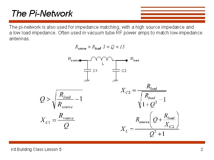
The Pi-Network The pi-network is also used for impedance matching, with a high source impedance and a low load impedance. Often used in vacuum tube RF power amps to match low-impedance antennas. Rsource > Rload, 5 < Q < 15 Rsource L C 1 Kit Building Class Lesson 5 Rload C 2 2
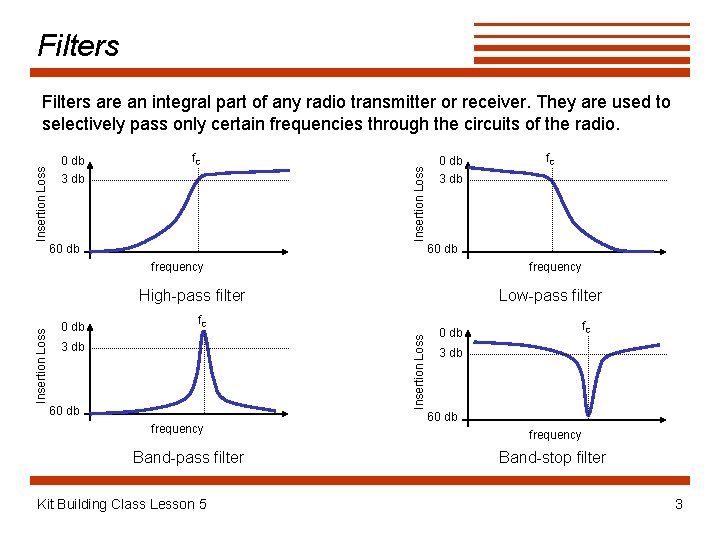
Filters 0 db 3 db f. C Insertion Loss Filters are an integral part of any radio transmitter or receiver. They are used to selectively pass only certain frequencies through the circuits of the radio. 60 db 3 db 60 db frequency Low-pass filter f. C Insertion Loss High-pass filter 0 db f. C 3 db 60 db frequency Band-pass filter Kit Building Class Lesson 5 f. C 0 db 3 db 60 db frequency Band-stop filter 3
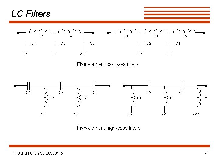
LC Filters L 2 L 4 C 1 L 1 C 3 L 3 C 5 L 5 C 2 C 4 Five-element low-pass filters C 1 C 3 L 2 C 5 L 4 C 2 L 1 C 4 L 3 L 5 Five-element high-pass filters Kit Building Class Lesson 5 4
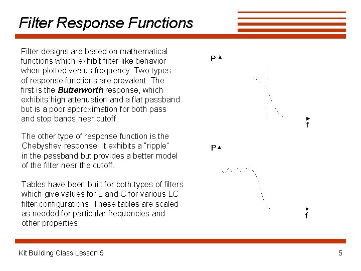
Filter Response Functions Filter designs are based on mathematical functions which exhibit filter-like behavior when plotted versus frequency. Two types of response functions are prevalent. The first is the Butterworth response, which exhibits high attenuation and a flat passband but is a poor approximation for both pass and stop bands near cutoff. The other type of response function is the Chebyshev response. It exhibits a “ripple” in the passband but provides a better model of the filter near the cutoff. Tables have been built for both types of filters which give values for L and C for various LC filter configurations. These tables are scaled as needed for particular frequencies and other properties. Kit Building Class Lesson 5 5
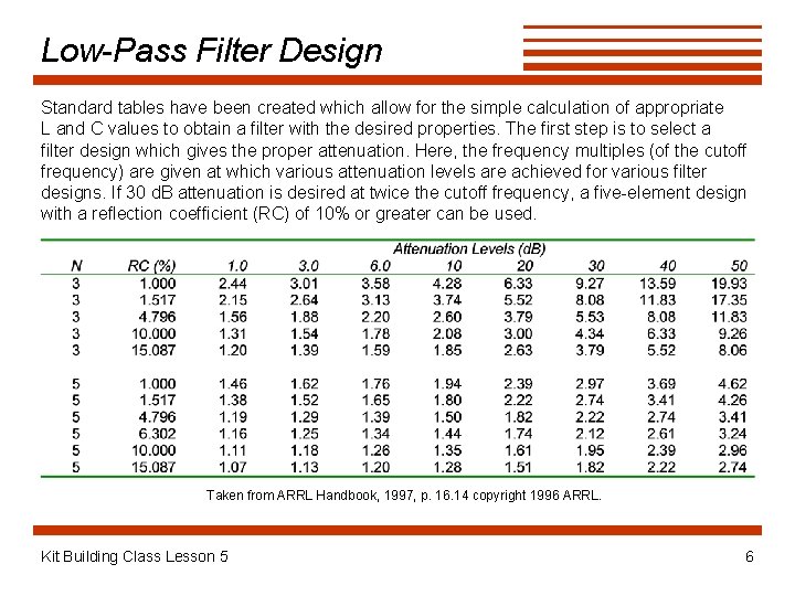
Low-Pass Filter Design Standard tables have been created which allow for the simple calculation of appropriate L and C values to obtain a filter with the desired properties. The first step is to select a filter design which gives the proper attenuation. Here, the frequency multiples (of the cutoff frequency) are given at which various attenuation levels are achieved for various filter designs. If 30 d. B attenuation is desired at twice the cutoff frequency, a five-element design with a reflection coefficient (RC) of 10% or greater can be used. Taken from ARRL Handbook, 1997, p. 16. 14 copyright 1996 ARRL. Kit Building Class Lesson 5 6
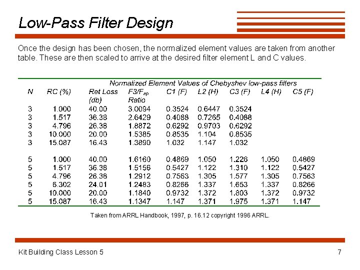
Low-Pass Filter Design Once the design has been chosen, the normalized element values are taken from another table. These are then scaled to arrive at the desired filter element L and C values. Taken from ARRL Handbook, 1997, p. 16. 12 copyright 1996 ARRL. Kit Building Class Lesson 5 7
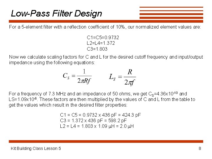
Low-Pass Filter Design For a 5 -element filter with a reflection coefficient of 10%, our normalized element values are: C 1=C 5=0. 9732 L 2=L 4=1. 372 C 3=1. 803 Now we calculate scaling factors for C and L for the desired cutoff frequency and input/output impedance using the following equations: For a frequency of 7. 3 MHz and an impedance of 50 ohms, we get CS=4. 36 x 10 -10 and LS=1. 09 x 10 -6. These factors are then multiplied by the values of C and L from the table to get the values which result in the desired filter properties: C 1 = C 5 = 0. 9732 x 436 p. F = 424. 3 p. F C 3 = 1. 372 x 436 p. F = 598. 2 p. F L 2 = L 4 = 1. 803 x 1. 09 m. H = 2. 0 m. H Kit Building Class Lesson 5 8
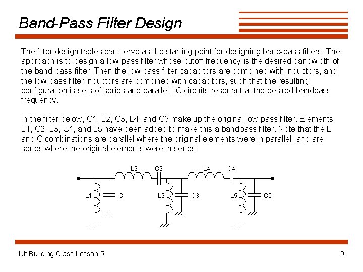
Band-Pass Filter Design The filter design tables can serve as the starting point for designing band-pass filters. The approach is to design a low-pass filter whose cutoff frequency is the desired bandwidth of the band-pass filter. Then the low-pass filter capacitors are combined with inductors, and the low-pass filter inductors are combined with capacitors, such that the resulting configuration is sets of series and parallel LC circuits resonant at the desired bandpass frequency. In the filter below, C 1, L 2, C 3, L 4, and C 5 make up the original low-pass filter. Elements L 1, C 2, L 3, C 4, and L 5 have been added to make this a bandpass filter. Note that the L and C combinations are parallel where the original elements were in parallel, and are series where the original elements were in series. L 2 L 1 Kit Building Class Lesson 5 C 1 C 2 L 3 L 4 C 3 C 4 L 5 C 5 9
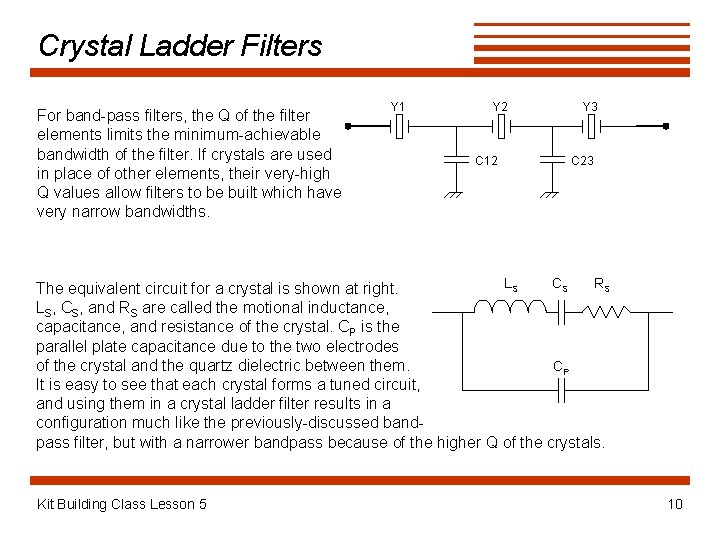
Crystal Ladder Filters For band-pass filters, the Q of the filter elements limits the minimum-achievable bandwidth of the filter. If crystals are used in place of other elements, their very-high Q values allow filters to be built which have very narrow bandwidths. Y 1 Y 2 C 12 Y 3 C 23 LS CS RS The equivalent circuit for a crystal is shown at right. LS, CS, and RS are called the motional inductance, capacitance, and resistance of the crystal. CP is the parallel plate capacitance due to the two electrodes of the crystal and the quartz dielectric between them. CP It is easy to see that each crystal forms a tuned circuit, and using them in a crystal ladder filter results in a configuration much like the previously-discussed bandpass filter, but with a narrower bandpass because of the higher Q of the crystals. Kit Building Class Lesson 5 10
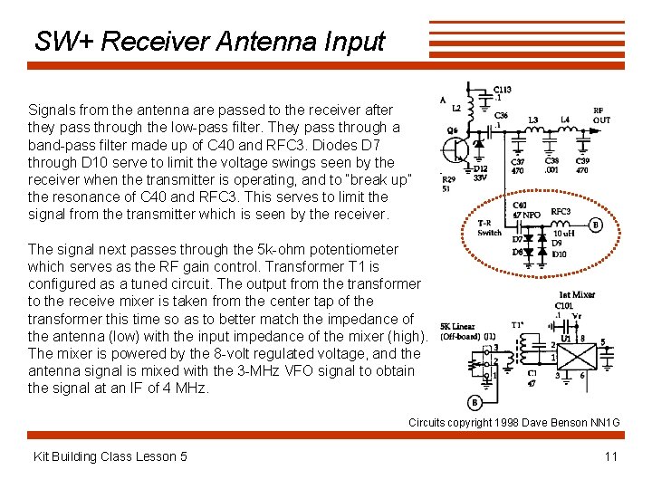
SW+ Receiver Antenna Input Signals from the antenna are passed to the receiver after they pass through the low-pass filter. They pass through a band-pass filter made up of C 40 and RFC 3. Diodes D 7 through D 10 serve to limit the voltage swings seen by the receiver when the transmitter is operating, and to “break up” the resonance of C 40 and RFC 3. This serves to limit the signal from the transmitter which is seen by the receiver. The signal next passes through the 5 k-ohm potentiometer which serves as the RF gain control. Transformer T 1 is configured as a tuned circuit. The output from the transformer to the receive mixer is taken from the center tap of the transformer this time so as to better match the impedance of the antenna (low) with the input impedance of the mixer (high). The mixer is powered by the 8 -volt regulated voltage, and the antenna signal is mixed with the 3 -MHz VFO signal to obtain the signal at an IF of 4 MHz. Circuits copyright 1998 Dave Benson NN 1 G Kit Building Class Lesson 5 11
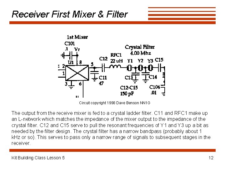
Receiver First Mixer & Filter Circuit copyright 1998 Dave Benson NN 1 G The output from the receive mixer is fed to a crystal ladder filter. C 11 and RFC 1 make up an L-network which matches the impedance of the mixer output to the impedance of the crystal filter. C 12 and C 15 serve to pull the resonant frequencies of Y 1 and Y 3 up a bit as needed by the filter design. The crystal filter has a narrow bandpass (probably about 1 k. Hz or so). This serves to pass only a narrow range of signals to subsequent stages in the receiver. Kit Building Class Lesson 5 12
Construction Part 1 • Install the following parts (some you may have installed previously): – – – • T 1 C 1, C 40, C 101 D 7, D 8, D 9, D 10 RFC 3 Socket for U 1 Lightly solder a jumper (use a leftover lead from an installed component) from the base of Q 6 (leftmost hole) to the top hole for C 36 (this leaks some transmitter signal to the receiver for testing) Kit Building Class Lesson 5 • • • Connect power jack, tuning pot, gain pot, and key jack. Connect a key to the key jack, or use a jumper to short the contacts. Turn gain pot all the way up. Connect power. Key down, use oscilloscope to check for a signal at the output (pin 5) of U 1. What kind of waveform do you see? You should see a complex waveform much like we saw coming out of U 5 in the transmitter. 13
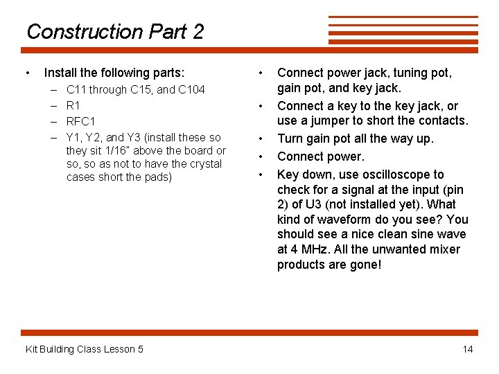
Construction Part 2 • Install the following parts: – – C 11 through C 15, and C 104 R 1 RFC 1 Y 1, Y 2, and Y 3 (install these so they sit 1/16” above the board or so, so as not to have the crystal cases short the pads) Kit Building Class Lesson 5 • • • Connect power jack, tuning pot, gain pot, and key jack. Connect a key to the key jack, or use a jumper to short the contacts. Turn gain pot all the way up. Connect power. Key down, use oscilloscope to check for a signal at the input (pin 2) of U 3 (not installed yet). What kind of waveform do you see? You should see a nice clean sine wave at 4 MHz. All the unwanted mixer products are gone! 14