
PACIFIC UNIVERSITY TEAM INTRODUCTION Crystal Lang ARCHITECT Robert

PACIFIC UNIVERSITY
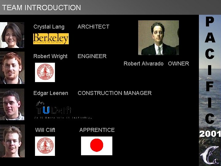
TEAM INTRODUCTION Crystal Lang ARCHITECT Robert Wright ENGINEER Robert Alvarado OWNER Edgar Leenen Will Clift CONSTRUCTION MANAGER APPRENTICE P A C I F I C 2001
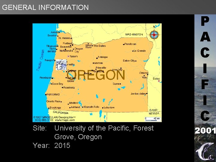
GENERAL INFORMATION Site: University of the Pacific, Forest Grove, Oregon Year: 2015 P A C I F I C 2001
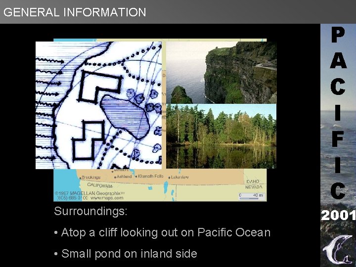
GENERAL INFORMATION Surroundings: • Atop a cliff looking out on Pacific Ocean • Small pond on inland side P A C I F I C 2001
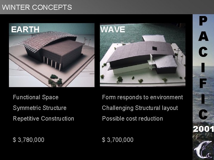
WINTER CONCEPTS EARTH WAVE Functional Space Form responds to environment Symmetric Structure Challenging Structural layout Repetitive Construction Possible cost reduction P A C I F I C 2001 $ 3, 780, 000 $ 3, 700, 000
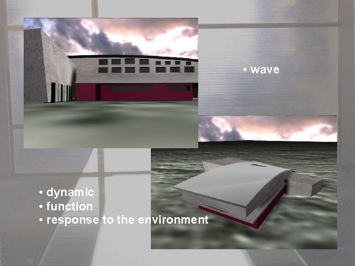
• wave • dynamic • function • response to the environment
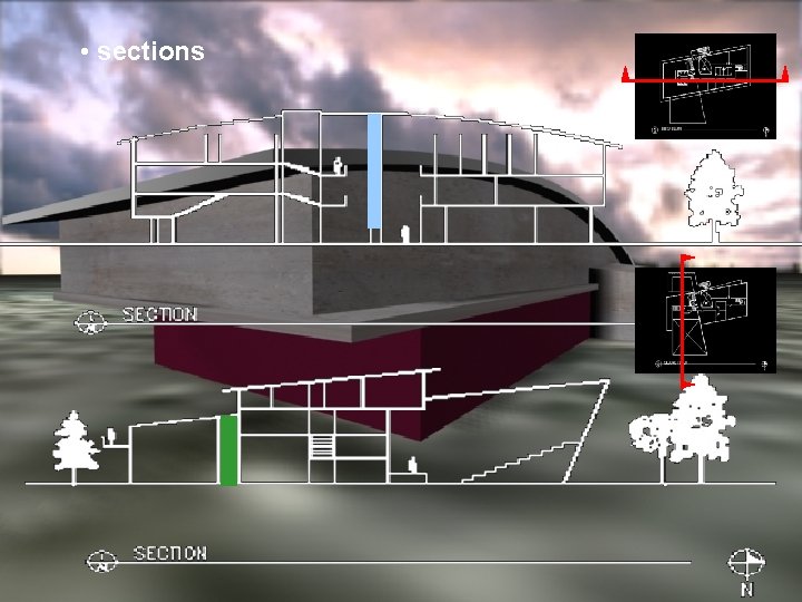
• sections
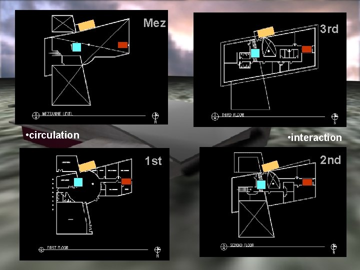
Mez • circulation 3 rd • interaction 1 st 2 nd
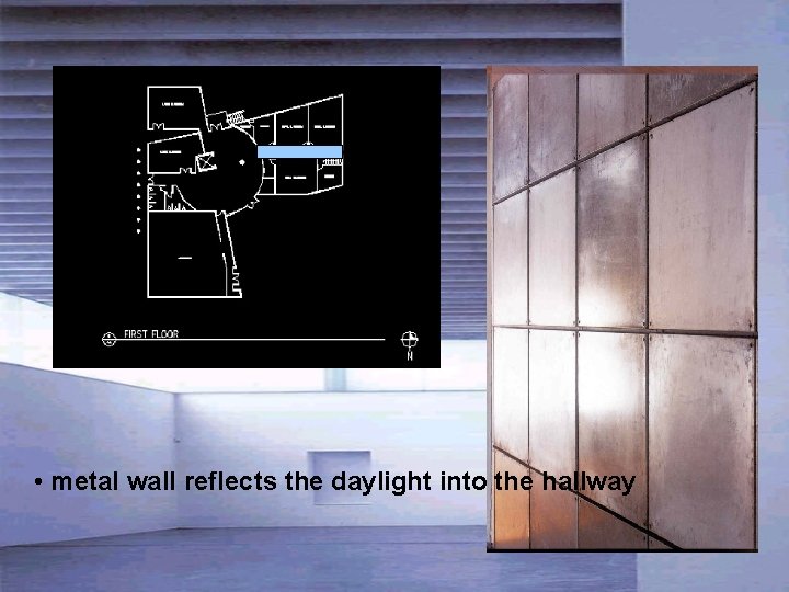
• metal wall reflects the daylight into the hallway
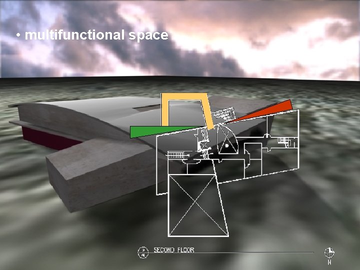
• multifunctional space
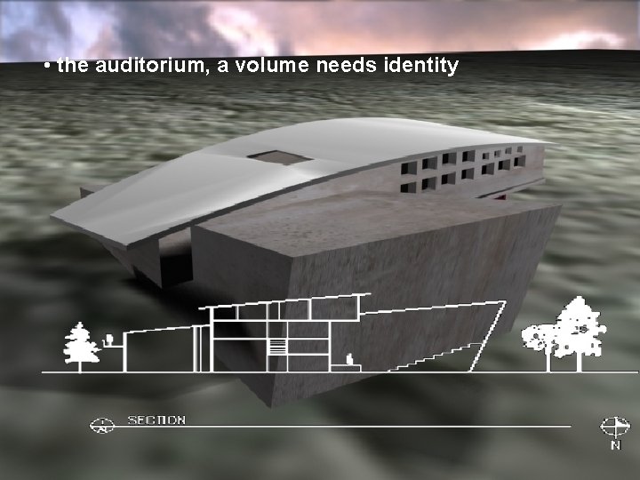
• the auditorium, a volume needs identity
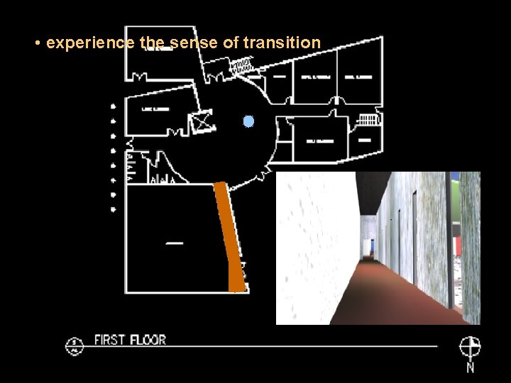
• experience the sense of transition
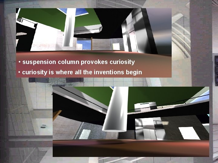
atmosphere of the interior gathering space • suspension column provokes curiosity • curiosity is where all the inventions begin
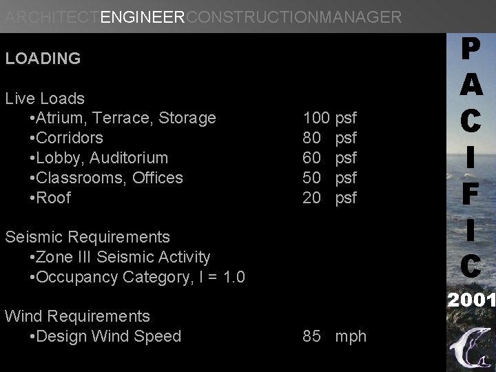
ARCHITECTENGINEERCONSTRUCTIONMANAGER LOADING Live Loads • Atrium, Terrace, Storage • Corridors • Lobby, Auditorium • Classrooms, Offices • Roof 100 psf 80 psf 60 psf 50 psf 20 psf Seismic Requirements • Zone III Seismic Activity • Occupancy Category, I = 1. 0 Wind Requirements • Design Wind Speed P A C I F I C 2001 85 mph
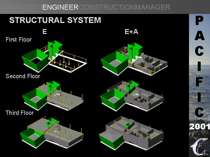
ARCHITECTENGINEERCONSTRUCTIONMANAGER STRUCTURAL SYSTEM E First Floor Second Floor Third Floor E+A P A C I F I C 2001
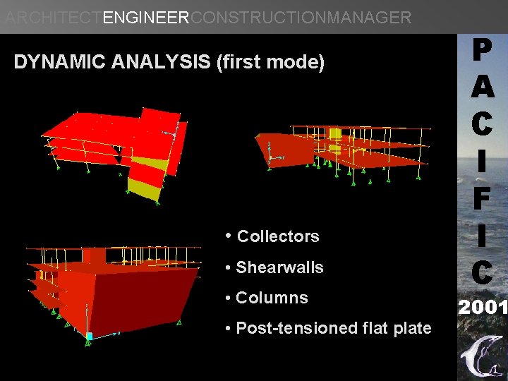
ARCHITECTENGINEERCONSTRUCTIONMANAGER DYNAMIC ANALYSIS (first mode) • Collectors • Shearwalls • Columns • Post-tensioned flat plate P A C I F I C 2001
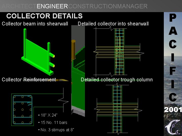
ARCHITECTENGINEERCONSTRUCTIONMANAGER COLLECTOR DETAILS Collector beam into shearwall Collector Reinforcement • 18” X 24” • 15 No. 11 bars • No. 3 stirrups at 8” Detailed collector into shearwall Detailed collector trough column P A C I F I C 2001
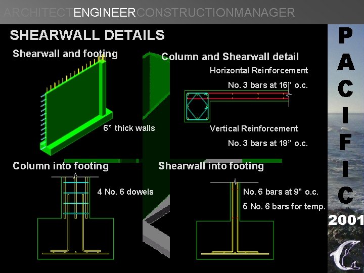
ARCHITECTENGINEERCONSTRUCTIONMANAGER SHEARWALL DETAILS Shearwall and footing Column and Shearwall detail Horizontal Reinforcement No. 3 bars at 16” o. c. 6” thick walls Vertical Reinforcement No. 3 bars at 18” o. c. Column into footing 4 No. 6 dowels Shearwall into footing No. 6 bars at 9” o. c. 5 No. 6 bars for temp. P A C I F I C 2001
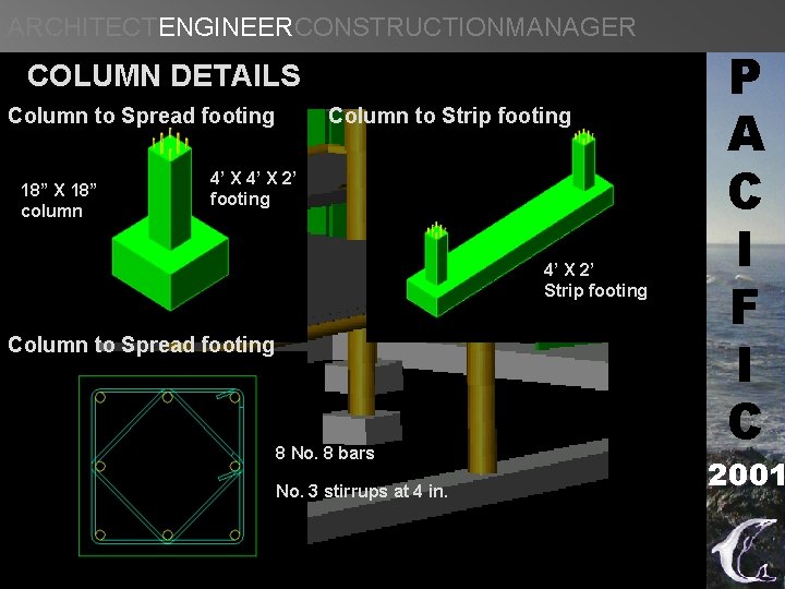
ARCHITECTENGINEERCONSTRUCTIONMANAGER COLUMN DETAILS Column to Spread footing 18” X 18” column Column to Strip footing 4’ X 2’ Strip footing Column to Spread footing 8 No. 8 bars No. 3 stirrups at 4 in. P A C I F I C 2001
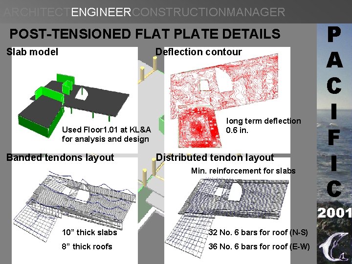
ARCHITECTENGINEERCONSTRUCTIONMANAGER POST-TENSIONED FLAT PLATE DETAILS Slab model Deflection contour Used Floor 1. 01 at KL&A for analysis and design Banded tendons layout long term deflection 0. 6 in. Distributed tendon layout Min. reinforcement for slabs P A C I F I C 2001 10” thick slabs 32 No. 6 bars for roof (N-S) 8” thick roofs 36 No. 6 bars for roof (E-W)
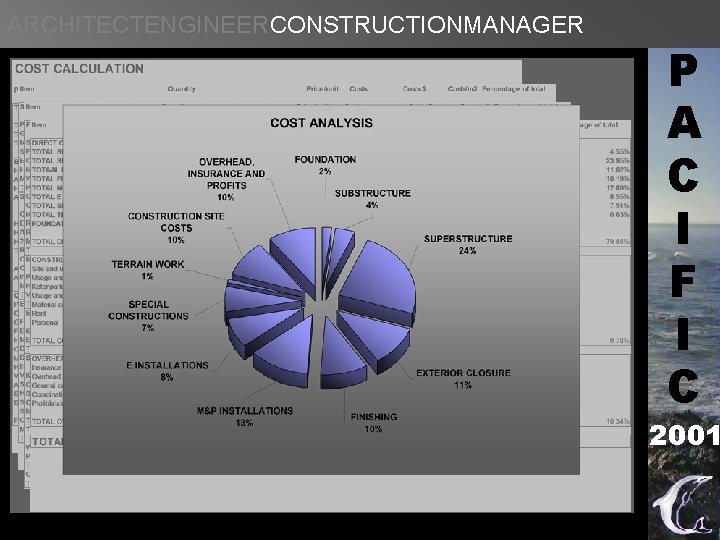
ARCHITECTENGINEERCONSTRUCTIONMANAGER $ 3, 553, 000 P A C I F I C 2001
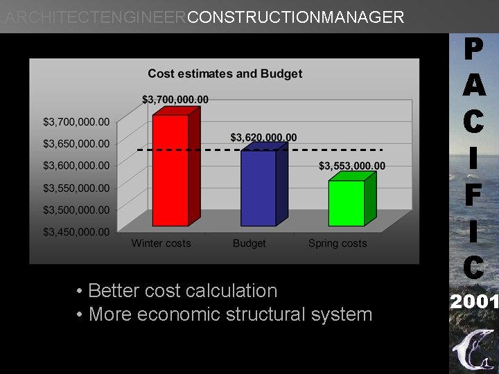
ARCHITECTENGINEERCONSTRUCTIONMANAGER • Better cost calculation • More economic structural system P A C I F I C 2001
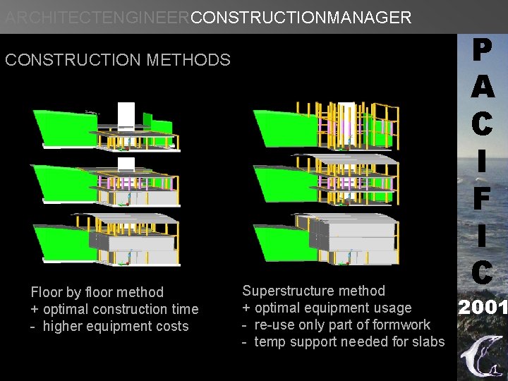
ARCHITECTENGINEERCONSTRUCTIONMANAGER CONSTRUCTION METHODS Floor by floor method + optimal construction time - higher equipment costs Superstructure method + optimal equipment usage - re-use only part of formwork - temp support needed for slabs P A C I F I C 2001
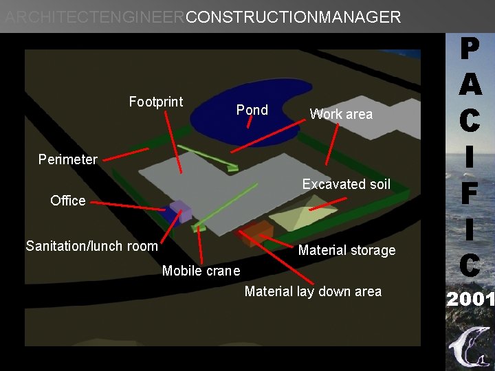
ARCHITECTENGINEERCONSTRUCTIONMANAGER Footprint Pond Work area Perimeter Excavated soil Office Sanitation/lunch room Material storage Mobile crane Material lay down area P A C I F I C 2001
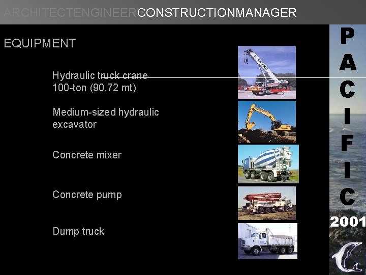
ARCHITECTENGINEERCONSTRUCTIONMANAGER EQUIPMENT Hydraulic truck crane 100 -ton (90. 72 mt) Medium-sized hydraulic excavator Concrete mixer Concrete pump Dump truck P A C I F I C 2001
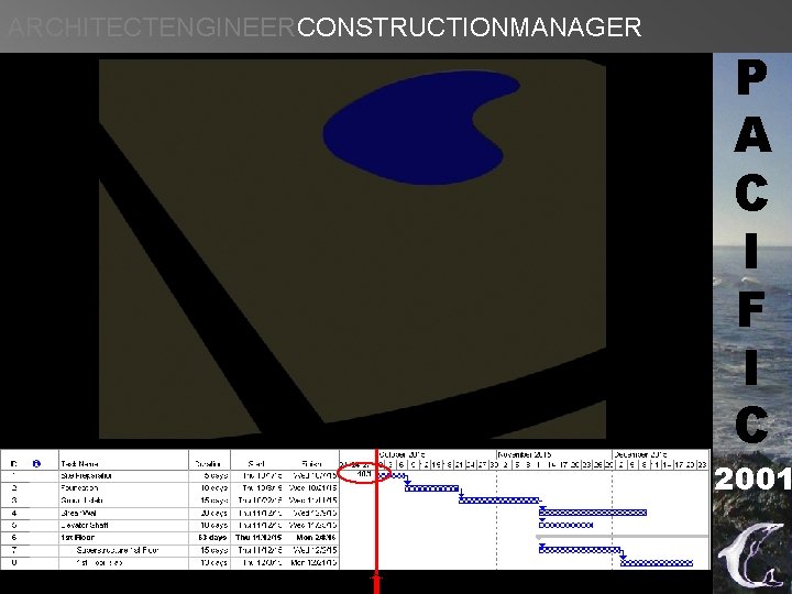
ARCHITECTENGINEERCONSTRUCTIONMANAGER P A C I F I C 2001
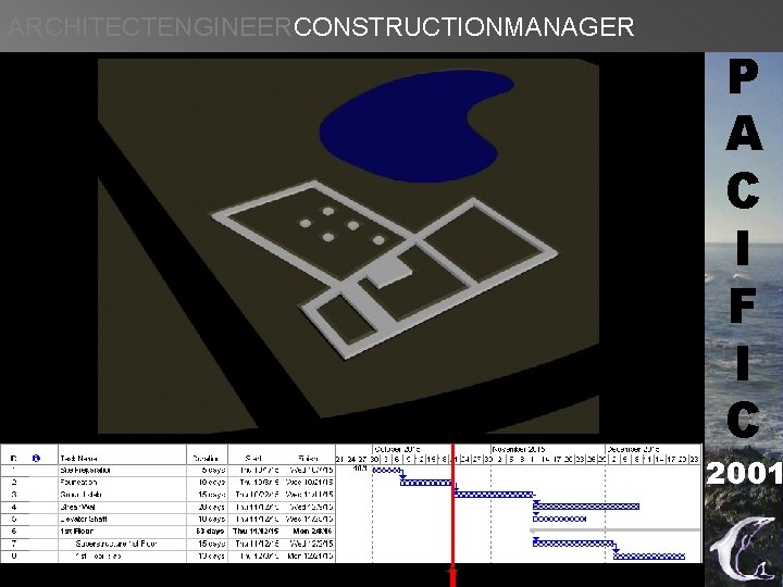
ARCHITECTENGINEERCONSTRUCTIONMANAGER P A C I F I C 2001
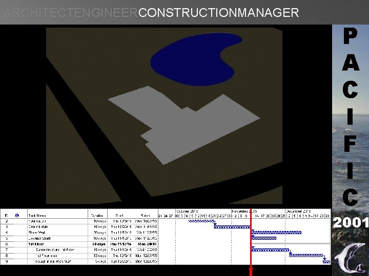
ARCHITECTENGINEERCONSTRUCTIONMANAGER P A C I F I C 2001
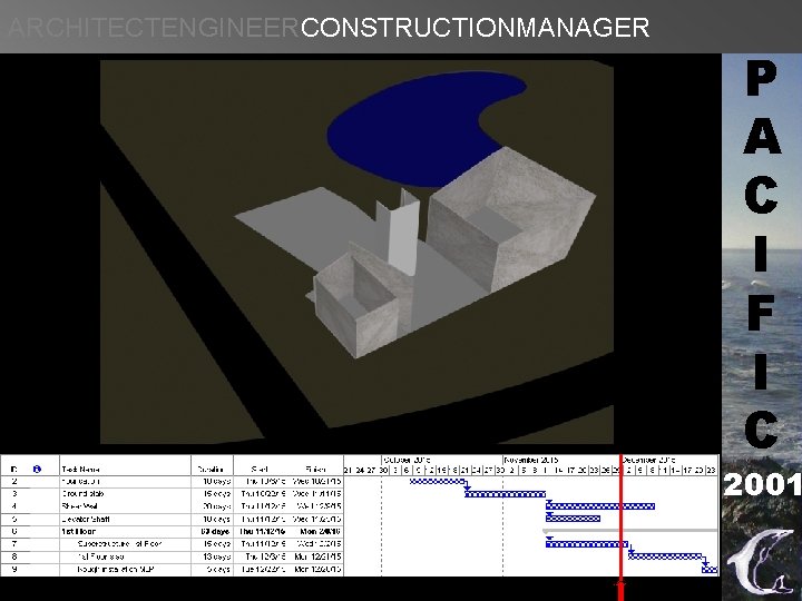
ARCHITECTENGINEERCONSTRUCTIONMANAGER P A C I F I C 2001
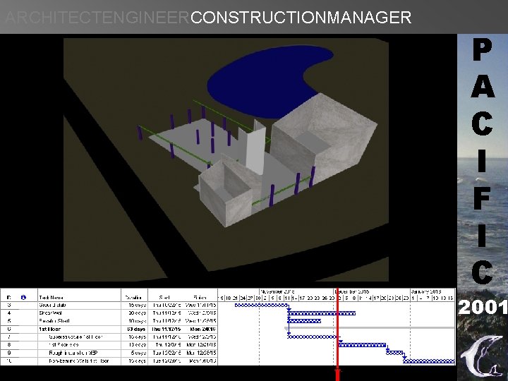
ARCHITECTENGINEERCONSTRUCTIONMANAGER P A C I F I C 2001
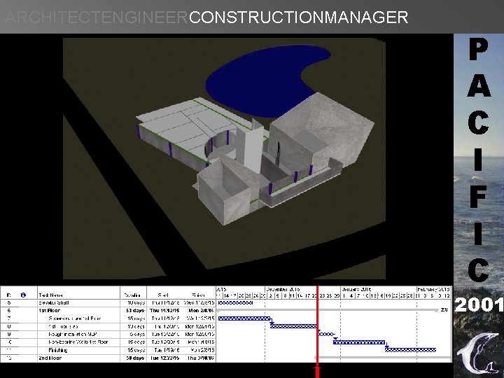
ARCHITECTENGINEERCONSTRUCTIONMANAGER P A C I F I C 2001
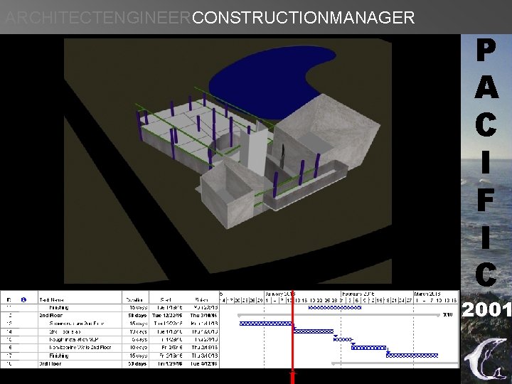
ARCHITECTENGINEERCONSTRUCTIONMANAGER P A C I F I C 2001
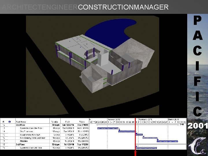
ARCHITECTENGINEERCONSTRUCTIONMANAGER P A C I F I C 2001
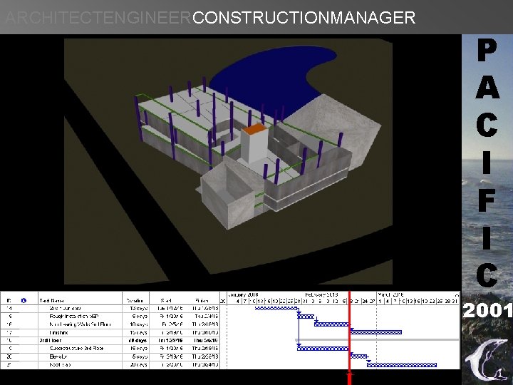
ARCHITECTENGINEERCONSTRUCTIONMANAGER P A C I F I C 2001
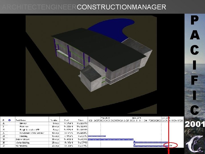
ARCHITECTENGINEERCONSTRUCTIONMANAGER P A C I F I C 2001
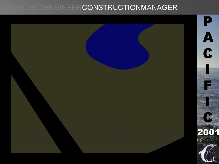
ARCHITECTENGINEERCONSTRUCTIONMANAGER P A C I F I C 2001
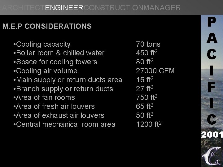
ARCHITECTENGINEERCONSTRUCTIONMANAGER M. E. P CONSIDERATIONS • Cooling capacity • Boiler room & chilled water • Space for cooling towers • Cooling air volume • Main supply or return ducts area • Branch supply or return ducts • Area of fan rooms • Area of fresh air louvers • Area of exhaust air louvers • Central mechanical room area 70 tons 450 ft 2 80 ft 2 27000 CFM 16 ft 2 27 ft 2 750 ft 2 65 ft 2 50 ft 2 1200 ft 2 P A C I F I C 2001
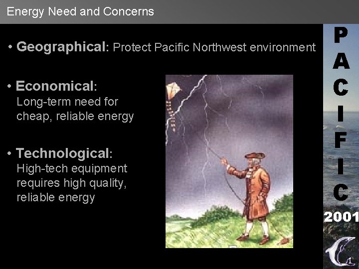
Energy Need and Concerns • Geographical: Protect Pacific Northwest environment • Economical: Long-term need for cheap, reliable energy • Technological: High-tech equipment requires high quality, reliable energy P A C I F I C 2001
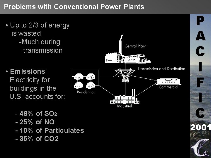
Problems with Conventional Power Plants • Up to 2/3 of energy is wasted -Much during transmission • Emissions: Electricity for buildings in the U. S. accounts for: - 49% of SO 2 - 25% of NO - 10% of Particulates - 35% of CO 2 P A C I F I C 2001
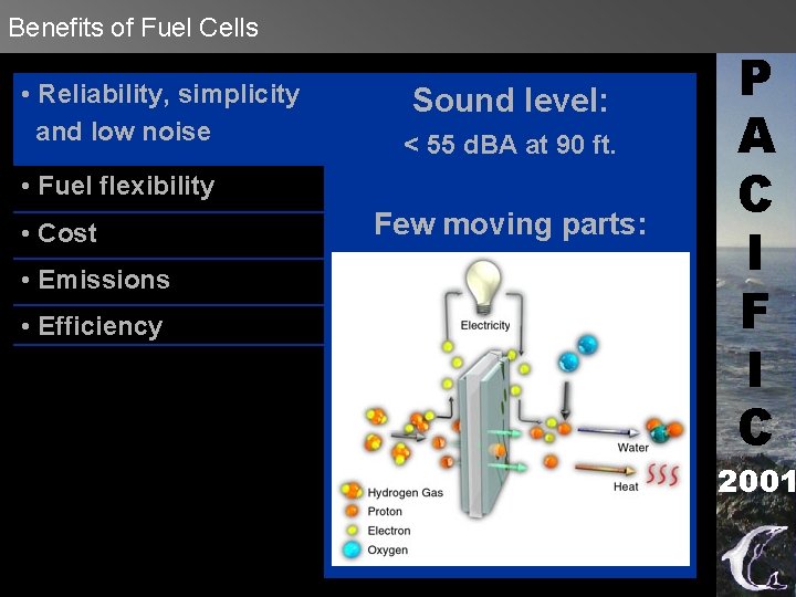
Benefits of Fuel Cells • Reliability, simplicity and low noise Sound level: < 55 d. BA at 90 ft. • Fuel flexibility • Cost • Emissions • Efficiency Few moving parts: P A C I F I C 2001
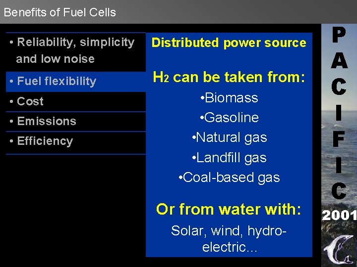
Benefits of Fuel Cells • Reliability, simplicity and low noise Distributed power source • Fuel flexibility H 2 can be taken from: • Cost • Emissions • Efficiency • Biomass • Gasoline • Natural gas • Landfill gas • Coal-based gas Or from water with: Solar, wind, hydroelectric… P A C I F I C 2001
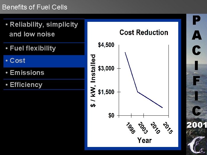
Benefits of Fuel Cells • Reliability, simplicity and low noise • Fuel flexibility • Cost • Emissions • Efficiency P A C I F I C 2001
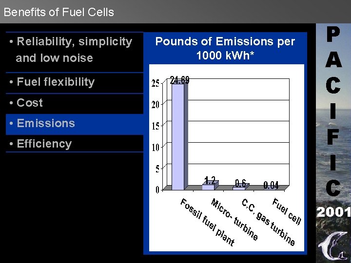
Benefits of Fuel Cells • Reliability, simplicity and low noise • Fuel flexibility • Cost • Emissions • Efficiency Pounds of Emissions per 1000 k. Wh* P A C I F I C 2001
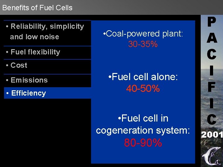
Benefits of Fuel Cells • Reliability, simplicity and low noise • Fuel flexibility • Coal-powered plant: 30 -35% • Cost • Emissions • Efficiency • Fuel cell alone: 40 -50% • Fuel cell in cogeneration system: 80 -90% P A C I F I C 2001
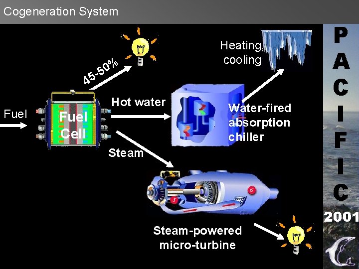
Cogeneration System Heating, cooling % 0 -5 45 Fuel Hot water Fuel Cell Water-fired absorption chiller Steam-powered micro-turbine P A C I F I C 2001
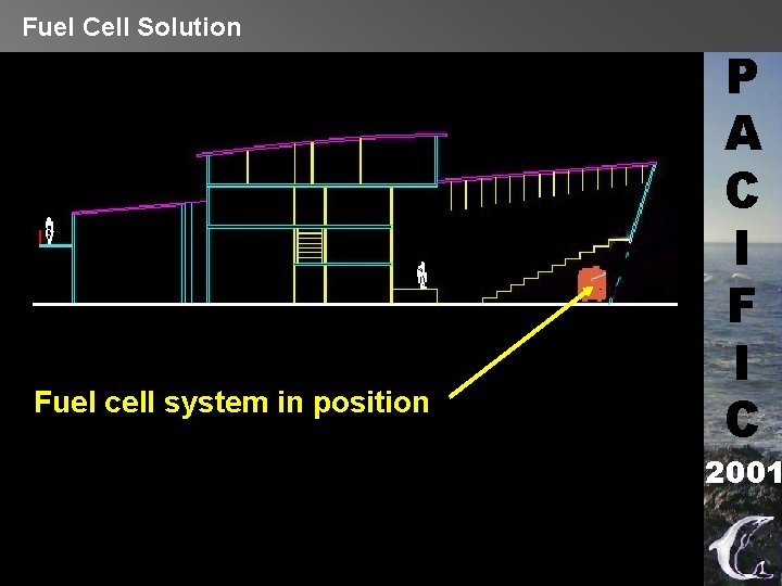
Fuel Cell Solution Fuel cell system in position P A C I F I C 2001
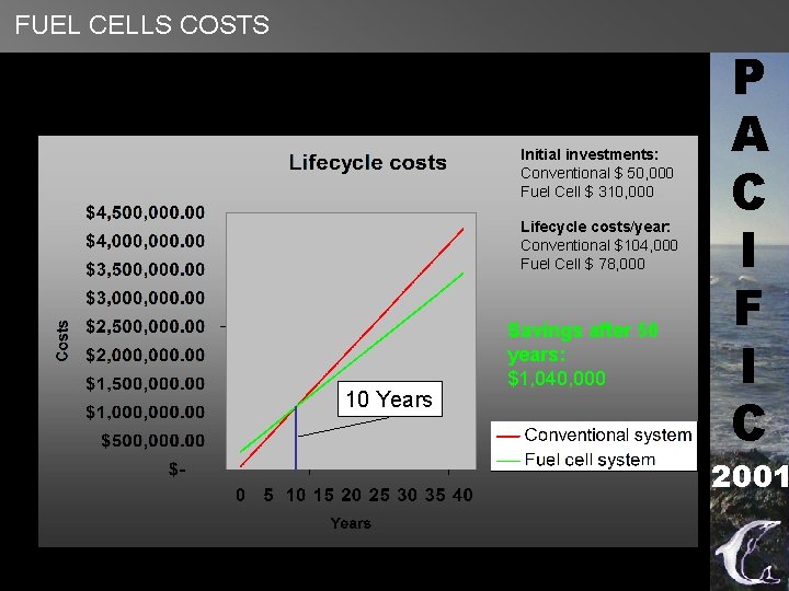
FUEL CELLS COSTS Initial investments: Conventional $ 50, 000 Fuel Cell $ 310, 000 Lifecycle costs/year: Conventional $104, 000 Fuel Cell $ 78, 000 10 Years Savings after 50 years: $1, 040, 000 P A C I F I C 2001
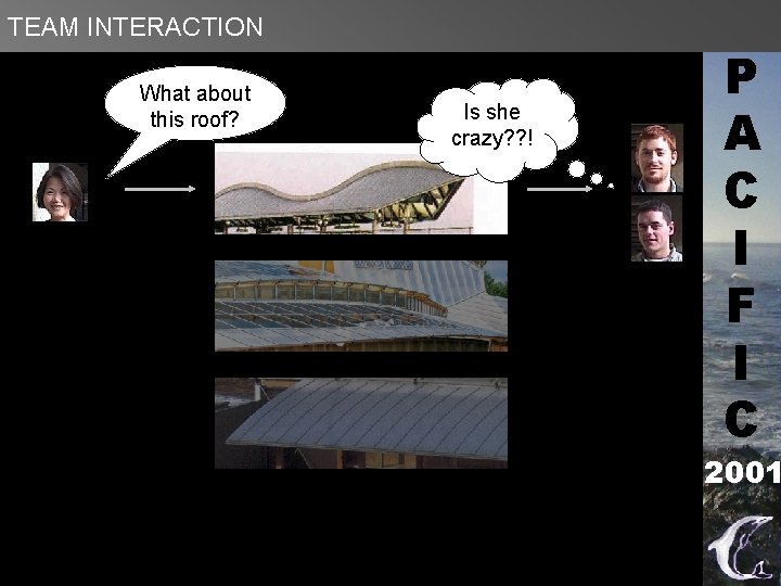
TEAM INTERACTION What about this roof? Is she crazy? ? ! P A C I F I C 2001
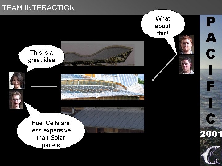
TEAM INTERACTION What about this! This is a great idea Fuel Cells are less expensive than Solar panels P A C I F I C 2001
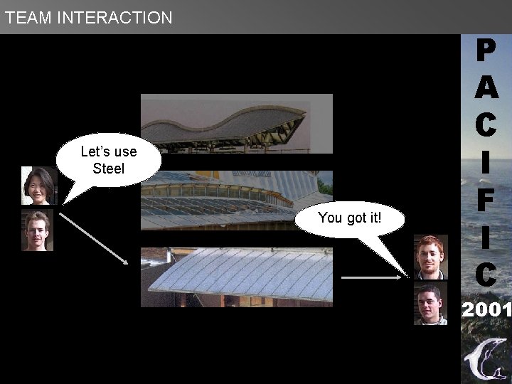
TEAM INTERACTION Let’s use Steel You got it! P A C I F I C 2001
LESSONS LEARNED AND IMPROVEMENTS LESSONS LEARNED • AEC collaboration requires disciplines to look beyond their box • Discipline interaction provides higher quality design solutions • JIT (Just In Time) Team planning causes stress IMPROVEMENTS SINCE WINTER QUARTER • Better communication with mentors • Disciplines shared same design model • Disciplines understood each others goals P A C I F I C 2001
THANK YOU We would like to thank all the mentors: Robert Alvarado, CM Salter Humberto Cavalli, University of California-Berkeley Renate Fruchter, Stanford University Ben Hendriks, HBG Helmut Krawinkler, Stanford University Shilin Jiang, KL&A Bart Luiten, HBG Greg Luth, KL&A Mike Martin, University of California-Berkeley Eduardo Miranda, Stanford University Cor Notenboom, HBG Rudger Smook, Delft University of Technology David Steinbach, Bauhaus University Bob Tatum, Stanford University P A C I F I C 2001
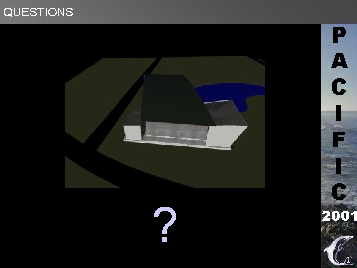
QUESTIONS ? P A C I F I C 2001
- Slides: 53