Advantages and Limitation of Map Reading Advantages The


 • The minimum acceptable angle of intercept for an inbound")


 • • Desired Course 360, Present Course 030 Desired Course 090,")

 • To avoid overshooting, an intercept angle greater than 45º")
 • • Desired Course 360, Radial 030 Desired Course 090, Radial")


 ADF 201 USE ADF BFO FRQ 263 STBY F/E S/R")
 A F B E C D Jeppesen Sanderson, Inc. 1998")


- Slides: 65
Advantages and Limitation of Map Reading Advantages • The best means of checking dead reckoning • No fix is more precise than a positive identification of an accurately mapped landmark. Limitation • It cannot be used when the ground is obscured by clouds or when flying over water • Landmarks cannot always be readily identified on a chart such as at night or if the chart is incomplete or inaccurate.
Section B VOR Navigation VERY HIGH FREQUENCY OMNIDIRECTIONAL RANGE
VOR Navigation VOR Stations Magnetic North 360° 270° 180° Jeppesen Sanderson, Inc. 1998 All Rights Reserved Guided Flight Discovery Private Pilot Manual 090°
VOR Facilities Standard High Altitude Service Volume 60, 000 ft 100 n. m. What Is The Range? 45, 000 ft 130 n. m. 18, 000 ft 14, 500 ft 100 n. m. 40 n. m. 1, 000 ft Standard Low Altitude Service Volume Standard Terminal Service Volume 12, 000 ft 40 n. m. 1, 000 ft 25 n. m. 1, 000 ft Jeppesen Sanderson, Inc. 1998 All Rights Reserved Guided Flight Discovery Private Pilot Manual
VOR Ground Equipment 40 Miles Line of Sight Limited One Degree Accuracy
VOR Airborne Equipment 30 27 24 21 OBS 120. 70 121. 90 112. 60 113. 0 33 0 3 6 9 18 15 12
VOR Navigation Procedures Station Identification
VOR Navigation Procedures Interpreting The Indications 360 320 180 270 Jeppesen Sanderson, Inc. 1998 All Rights Reserved Guided Flight Discovery Private Pilot Manual
Interpreting VOR Indications Orientation and Bracketing What happens at station passage? Jeppesen Sanderson, Inc. 1998 All Rights Reserved Guided Flight Discovery Private Pilot Manual
27 24 21 OBS 30 33 VOR Navigation Procedures Tracking A What heading Course/Radial 0 3 6 should be flown to get back on course? 9 18 15 12 150 Radial
VOR Navigation Procedures Tracking A Course/Radial 33 0 27 24 21 OBS 30 18 15 12 3 6 330 Crs To 9 Learn to Bracket
VOR Navigation Procedures Tracking A Course/Radial 33 0 30 27 3 24 6 21 9 18 15 12 OBS 330 Crs To Learn to Bracket Fly Hdg 310
27 24 21 OBS 30 33 VOR Navigation Procedures Tracking A 0 Course/Radial 330 Crs To 3 6 9 18 15 12 Wait to Center Learn to Bracket Fly Hdg 310
27 24 21 OBS 30 33 VOR Navigation Procedures Tracking A 0 Course/Radial 330 Crs To 3 6 9 18 15 12 Fly Hdg 320 to Crab Wait to Center Learn to Bracket Fly Hdg 310
27 24 21 OBS 30 33 VOR Navigation Procedures Tracking A 0 Course/Radial 330 Crs To 3 6 9 18 15 12 Monitor and Adjust Fly Hdg 320 to Crab Wait to Center Learn to Bracket Fly Hdg 310
VOR Intercepting (Inbound course) • The minimum acceptable angle of intercept for an inbound course interception must be greater than the number of degrees the aircraft is displaced from the desired course. • The angle of intercept should not exceed 90º
VOR Navigation Procedures Intercepting A Course/Radial Identify the Station • • Set in Desired Course 27 24 21 OBS 30 33 0 3 6 9 18 15 12
VOR Navigation Procedures Intercepting A Course/Radial Identify the Station • • Set in Desired Course • Parallel Desired Course Fly Hdg 330 27 24 21 OBS 30 33 0 3 6 9 18 15 12
VOR Navigation Procedures Intercepting A Course/Radial Identify the Station • • Set in Desired Course • Parallel Desired Course • Determine Amount Off Course 25 deg? 40 deg? 27 24 21 OBS 30 33 0 3 6 9 18 15 12
• • • VOR Navigation Procedures Intercepting A Course/Radial Identify the Station If over 30 deg, use 90 deg intercept angle. Set in Desired Course If 30 deg or less, use Parallel Desired Course 45 deg intercept. Determine Amount Off Course 30 27 Angle Towards the Needle 24 Wait to Center 21 OBS 33 0 3 6 9 18 15 12
• • VOR Navigation Procedures Intercepting A Course/Radial Identify the Station Set in Desired Course Parallel Desired Course Determine Amount Off Course 30 27 Angle Towards the Needle 24 Wait to Center 21 Begin Tracking 18 OBS 33 0 3 6 9 15 12
Intercept Heading (Inbound) • • Desired Course 360, Present Course 030 Desired Course 090, Present Course 030 Desired Course 180, Radial 020 Desired Course 270, Radial 040 045º 360º 225º 180º
Error • Desired course – ������� ± 30º • 30º ��� Desired course ������ Desired course ������� 30º • Desired course 360º, Present course 070 – Make sense?
VOR Intercepting (Outbound course) • To avoid overshooting, an intercept angle greater than 45º should not be used. • ��� – D ± 45º
Intercept Heading (Outbound) • • Desired Course 360, Radial 030 Desired Course 090, Radial 030 Desired Course 180, Radial 200 Desired Course 270, Radial 220 315º 135º 315º
VOR Navigation Procedures Cross-Checking Your Position s e e gr e D 0 06 31 0 D eg re e s
VOR Navigation Procedures Checking Equipment Accuracy • • Ground Checks Air Checks Dual Check Visual Check 27 24 21 OBS 30 18 33 0 3 6 15 9 12
VOR Navigation Procedures Airborne VOR Test Jeppesen Sanderson, Inc. 1998 All Rights Reserved Guided Flight Discovery Private Pilot Manual
• If TO/FROM indicator is To, turn left or right? • If your aircraft flies heading 150º, turn left or right? 27 24 21 OBS 30 33 0 3 6 9 18 15 12
VOR Navigation Procedures Why Do Pilots Love The DME? Instant Distance Instant Ground Speed Instant ETA Instant Location
VOR Navigation Procedures Slant Range Distance Jeppesen Sanderson, Inc. 1998 All Rights Reserved Guided Flight Discovery Private Pilot Manual
Section C NDB Navigation
NDB Ground Equipment Not Line of Sight Limited Pilot-Dependant Accuracy
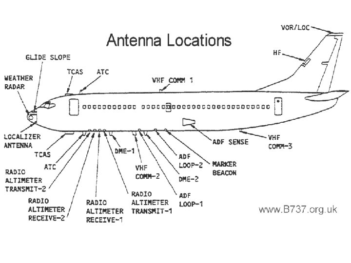
NDB Airborne Equipment (ADF) ADF 201 USE ADF BFO FRQ 263 STBY F/E S/R Jeppesen Sanderson, Inc. 1998 All Rights Reserved Guided Flight Discovery Private Pilot Manual
Radio Magnetic Indicator (RMI) A F B E C D Jeppesen Sanderson, Inc. 1998 All Rights Reserved Guided Flight Discovery Private Pilot Manual
NDB Navigation Procedures Station Identification Use REC mode to test/swing the needle. Press to Toggle REC ADF 201 USE ADF BFO FRQ 263 STBY F/E S/R
NDB Navigation Procedures Interpreting The Indications B A D C E F G
NDB Navigation Procedures Interpreting The Indications A B C D E F G
NDB Navigation Procedures Homing To The Station
NDB Navigation Procedures Homing To The Station Jeppesen Sanderson, Inc. 1998 All Rights Reserved Guided Flight Discovery Private Pilot Manual
NDB Navigation Procedures Tracking A Course/Bearing REMEMBER!
NDB Navigation Procedures Tracking A Course/Bearing • Are you holding heading steady? • Do you have a crab angle set in? • Does the crab angle match the pointer deflection? • Is the pointer stationary? • GOOD JOB!
NDB Navigation Procedures Tracking A Course/Bearing
NDB Navigation Procedures Tracking A Course/Bearing • Turn 20 degrees towards the pointer.
NDB Navigation Procedures Tracking A Course/Bearing • Turn 20 degrees towards the pointer.
NDB Navigation Procedures Tracking A Course/Bearing • Turn 20 degrees towards the pointer. • Wait for 20 deg of pointer deflection.
NDB Navigation Procedures Tracking A Course/Bearing • Turn 20 degrees towards the pointer. • Wait for 20 deg of pointer deflection. • Take out 10 deg and watch for pointer movement.
NDB Navigation Procedures Tracking A Course/Bearing • Turn 20 degrees towards the pointer. • Wait for 20 deg of pointer deflection. • Take out 10 deg and watch for pointer movement. • Bracket further if necessary.
NDB Navigation Procedures Intercepting A Course/Bearing • • • Reset Heading Indicator Tune/Ident/Test Parallel Course Decide on Intercept Angle Fly Intercept Angle Wait for Intercept Angle to Equal Pointer Deflection • Begin Tracking
ADF Limitations Pilot-Dependant Accuracy
ADF Limitations Pilot-Dependant Accuracy
ADF Limitations Pilot-Dependant Accuracy
ADF Limitations Pilot-Dependant Accuracy
ADF Limitations Pilot-Dependant Accuracy
For operations off established airways at 17, 000 feet MSL in the contiguous U. S. , (H) Class VORTAC facilities used to define a direct route of flight should be no farther apart than A-75 NM B-100 NM C-200 NM
VOR Facilities Standard High Altitude Service Volume 60, 000 ft 100 n. m. What Is The Range? 45, 000 ft 130 n. m. 18, 000 ft 14, 500 ft 100 n. m. 40 n. m. 1, 000 ft Standard Low Altitude Service Volume Standard Terminal Service Volume 12, 000 ft 40 n. m. 1, 000 ft 25 n. m. 1, 000 ft Jeppesen Sanderson, Inc. 1998 All Rights Reserved Guided Flight Discovery Private Pilot Manual
Where can the VOT frequency for a particular airport be found? A-On the IAP Chart and in the Airport/Facility Directory B-Only in the Airport/Facility Directory C-In the Airport/Facility Directory and on the A/G Voice Communication Panel of the en route Low Altitude Chart
Where does the DME indicator have the greatest error between ground distance to the VORTAC and displayed distance? A-High altitude far from the VORTAC B-High altitude close to VORTAC C-Low altitude far from the VORTAC How should a pilot determine when the DME is inoperative? A-The airborne DME will always indicate “ 0” mileage B-The airborne DME will “search”, but not “lock on” C-The airborne DME will may appear normal, but there will be no code tone
Which DME indication should you receive when you are directly over a VORTAC site approximately 6, 000 feet AGL? A-0 B-1 C-1. 3 To minimize DME slant range error, how far from the facility should you be to consider the reading as accurate? A-Two miles or more for each 1, 000 feet of altitude above facility B-One or miles for each 1, 000 feet of altitude above facility C-No specific distance is specified since the reception is line-of-sight
When making an airborne an VOR check, what is the maximum allowable tolerance between the two indicators of dual VOR system (units independent of each other except antenna)? A-4° between the two indicated bearings of a VOR B-Plus or minus 4° when set to identical radials of a VOR C-6° between the two indicated radials of VOR To minimize DME slant range error, how far from the facility should you be to consider the reading as accurate? A-Two miles or more for each 1, 000 feet of altitude above facility B-One or miles for each 1, 000 feet of altitude above facility C-No specific distance is specified since the reception is line-of-sight
What angular deviation from a VOR course centerline is represented by a full-scale reflection of the CDI? A-4° B-5° C-10° When using VOR for navigation, which of the following should be considered as station passage? A-The first movement of the CDI as the airplane enters the zone of confusion B-The moment the TO-FROM indicator becomes blank C-The first positive, complete reversal of the TO-FROM indicator
A VOR receiver with normal five-dot course sensitivity shows a threedot deflection at 30 NM from station. The aircraft would be displaced approximately how far from the course centerline ? A-2 NM B-3 NM C-5 NM Determine the approximate time and distance to a station if a 5° wingtip bearing change occurs in 1. 5 minutes with a true airspeed of 95 knots A-16 minutes and 14. 3 NM Time In Minutes = Seconds / Degrees Change B-18 minutes and 28. 5 NM Distance = Minutes x TAS / Degrees Change C-18 minutes and 33. 0 NM
Question?