Powder metallurgy Visit for more Learning Resources Co


 1) 2) 3) 4) 5) 6) Powder")

 Powder production • Powders are manufactured by various methods and the powder from")
 Powder production B) Crushing The solid materials are crushed by hammers, jaw crushers,")
 Roll crusher (b) Ball mill")
 Powder production In ball milling methods, the material to be powdered is tumbled")
 Powder production The size and characters of the powder depends on the temperature")


 Powder production Physical processes condensation: In this method , metal vapours are condensed")

Mixing or blending The metal obtained from above methods may not be suitable for")


 Cylindrical, (b)")

Compacting in metal dies is one of the most important methods for shaping of")

It reduces voids between powder")
 sintering Sintering is carried out to increase strength and hardness of a green")

 sintering uniformly because of variation in the density of compact and hence this")
 Sintering • Parts are heated to ~80% of melting temperature • Transforms compacted")
 sintering Depending upon temperature of sintering, sintering process is classified as solid phase")
sizing(coining) or impregnation: The sintered compact may have slightly different size from the desired")
 or impregnation: Due to this the interconnected porosity is likely to closed and")

Testing and inspection etc. 3) Sintering temp. and time, type of sintering etc. 4)")
Metal plus metal components can be manufactured by P/M. 2)Metal")
P/M parts may be welded, brazed, machined, heat treated, plated")
Most of the powder used in P/M are fine and")
Components with theoretical density can not be manufactured. 7)Due to")
Specific surface: It is defined as the total surface area")
 Tap density: The tap density is the apparent density")
compressibility: It is defined as the powder ability to under")
Decrease of particle irregularity e)decrease of particle hardness f) decrease")
 Bronze bearings are widely used and made up")
 The working of the bearing")
 Metal powder of cu and Sn with small")
 At this temp. a tin rich liquid phase")

 Automotive application In motor car industry, porous bearings are used")
High temp. application:")
 Aerospace application: Metal powder play an important role in rockets,")
 Other applications: Parts in clock and timing devices, typewriters, adding")


 version")


 High frequency sound waves are introduced into a material and they")


- Slides: 85
Powder metallurgy Visit for more Learning Resources
Co related to chapter • Use powder metallurgy processes for different engineering applications. • Describe Non destructive testing methods for engineering material testing.
Introduction • Powder metallurgy is a branch of metallurgy which deals with the production of metal and nonmetal powders and subsequently manufacture of components by using these powders. • It is process in which powdered materials are BLENDED, PRESSED into desired shape and then HEATED to bond surface.
Steps involved in production of component (processes) 1) 2) 3) 4) 5) 6) Powder production Blending or mixing Compacting(i. e. pressing) Sintering Sizing or impregnation Testing and inspection.
Powder Metallurgy Steps involved in manufacturing powder metallurgical component
1) Powder production • Powders are manufactured by various methods and the powder from each method has typical properties. 1) Mechanical process a) Machining This method is used to produce filings, turning , chips etc. which are subsequently pulverized by crushing and milling. Since relatively coarse powders are obtained by this method, it is suitable only for few special cases such as Mg powder in pyrotechnic applications, silver solders and dental alloys. The powder particles are of irregular shape.
1) Powder production B) Crushing The solid materials are crushed by hammers, jaw crushers, gyratory crushers, etc. the powder particles of brittle material are angular in shape and ductile material are flaky in shape. Any material can be crushed to powder form; however, the method is very much suitable for brittle materials. C) Milling: Milling is the most important and widely used method for the production of powders of required grade and fineness. Milling is done by using equipments such as ball mills, rod mills, eddy mills etc.
Powder Production q Mechanical: (a) Roll crusher (b) Ball mill
1) Powder production In ball milling methods, the material to be powdered is tumbled or rotated in a container with large number of hard balls. The speed of container is properly controlled so that the balls hit the material making particles finer and finer. Milling may be done by dry or wet method. In wet method, a liquid medium such as distilled water , alcohol, acetone, or stearic acid is used in the drum. Any type of material can be powdered by milling method. However it is widely used for carbide –metal mixtures. D) shotting: In this method molten metal is poured on a vibrating screen and liquid droplets are solidified either in air or a neutral gas.
1) Powder production The size and characters of the powder depends on the temperature of molten metal, size of openings in the screen and frequency of vibrations of the screen. Shape of particle is nearly spherical. E)Graining : Graining involves the same procedure as shotting, the only difference being the solidification of molten metal droplet is done in water. The powder obtained by shotting and graining method are coarse and subsequently pulverization methods are used for further reduction of size.
Powder Production q Mechanical: Automization Ø Produce a liquid-metal stream by injecting molten metal through a small orifice Ø Stream is broken by jets of inert gas, air, or water Ø The size of the particle formed depends on: Temperature of the metal Metal flowrate through the orifice Pressure of jet Nozzle size and jet characteristics
Powder Production The process consists of main three stages • Melting • Atomization • Solidification and cooling Ø Melting is done by induction, arc, plasma or electron-beam technique to maintain purity of melt. Ø Atomization is done by high velocity water, compressed air or inert gas. Ø The disintegrated particles are solidified in controlled atmosphere, vacuum , air or water. • Main two types of techniques: • Water Atomization • Gas Atomization
Powder Production Main two types of Automization Techniques: Water Atomization Gas Atomization
Gas Atomisation Compressed air, nitrogen, argon or helium are used for disintegration.
Water Automization Water atomization technique for production of powders
1) Powder production Physical processes condensation: In this method , metal vapours are condensed to obtain metal powders. This method is highly suitable for volatile metals because they get easily transformed to their vapours. Large quantities of Zn , Mg and Cd powders are manufactured by this method. The powder shape is nearly spherical.
Characteristic of Metal powder • • • Chemical composition Particle shape, size and its distribution Particle porosity Specific surface Compacting properties Sintering properties
2)Mixing or blending The metal obtained from above methods may not be suitable for their further processing. To make them suitable, powder conditioning is done which involves mechanical, chemical or thermal treatments or alloying and are described below: 1)Annealing : Before mixing or blending of powders, annealing is usually done in reducing atmosphere or in vacuums. This eliminates work hardening effect, reduces the oxide content and impurity level and alters the apparent density. High temp. annealing increases the apparent density of powder and reduces the pressure requirements: whereas,
Mixing or blending low temp annealing decreases apparent density of powder and increases the pressure requirements during compaction. These powder form a spongy mass during annealing and hence it is pulverized to obtain powder. Mixing or blending. In this process , through mixing of powders of same material or of different material is done for obtaining the desired properties during compaction , sintering and in the final sintered component.
Mixing or blending This gives uniform distribution of particles in the compact and consistent performance of the powder during pressing or sintering. For obtaining this at improved levels, small amount of lauryl alcohol or camphor is usually added to the powder during mixing. This also improves bonding of particles which improves green strength of compacts. Various types of machines are used for mixing or blending; however a double cone or y cone mixer is more common.
Blending and Mixing Some common equipment geometries used for blending powders (a) Cylindrical, (b) rotating cube, (c) double cone, (d) twin shell
Mixing or blending Certain material like graphite, Mos 2, stearic acid, stearates of Zn and Li, etc are added to these powders during mixing which may have one or more of the following functions: 1)It may acts as a lubricant, reducing the friction between the punch and the die walls. 2)It may easily transform to a gas or vapour which creates porosity during sintering. This can be used to control porosity of the component. 3)It may acts as binder , increasing green strength which facilitates handling of cold compacts.
3)Compacting in metal dies is one of the most important methods for shaping of metal powders. Powder mix is fed in to the die cavity through a hopper and feed shoe. And feed shoe is oscillated to assist the powder flow. The volume of the powder is controlled by adjusting the position of the bottom punch in the die cavity. When the die has been evenly filled with powder, these upper surface is leveled by a sweep of feed shoe and top punch is pushed in to the die cavity. The pressure is then applied on any one punch or simultaneously on both the punches to compact the powder.
Compacting After maximum compression the upper punch is removed and the compact is ejected by raising the lower punch, leaving it free for next similar operation.
Compacting Most important effect of compacting are as follows 1)It reduces voids between powder particles and increases the density of compact. 2)It produces adhesion and cold welding of the powders and gives sufficient green strength. 3)It is plastically deforms the powder and allows recrystallization during subsequent sintering.
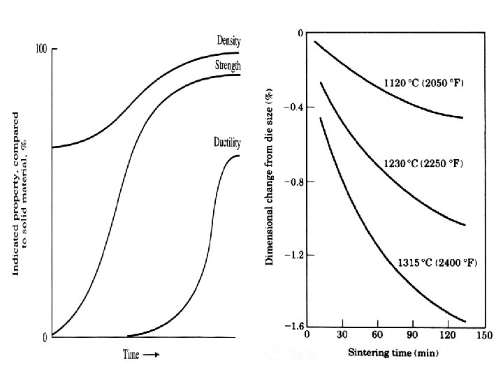
4) sintering Sintering is carried out to increase strength and hardness of a green compact and consists of heating the compact to some temperature under controlled conditions with or without pressure for a definite time. Sintering process is concerned with: A) Diffusion: this takes place especially on the surface of the particles as the temperature rises. B) Densification: this decreases porosity present in the green compact and increases the particle contact area. Due to this, the compact size decreases. This decrease may not occur
Sintering The possible diffusion mechanisms are q. Surface diffusion q. Volume diffusion q. Grain boundary diffusion q. Evaporation and condensation
4) sintering uniformly because of variation in the density of compact and hence this leads to the distortion of component. c) Recrystallization and grain growth: This occurs between the particle at the contact area, leading to a structure similar to original one.
4) Sintering • Parts are heated to ~80% of melting temperature • Transforms compacted mechanical bonds to much stronger metal bonds • Many parts are done at this stage. Some will require additional processing
4) sintering Depending upon temperature of sintering, sintering process is classified as solid phase sintering or liquid phase sintering. The most common method is solid phase sintering in which the green compacts are heated usually above the recrystallization temperature of low melting metal. The liquid phase sintering is carried out above the melting point of one of the alloy constituents or above the melting point of an alloy formed during sintering.
5)sizing(coining) or impregnation: The sintered compact may have slightly different size from the desired one due to distortion occurring during the sintering process. The size restriction is done by placing the component in a master die and applying pressure. This is called sizing
sizing(coining) or impregnation: Due to this the interconnected porosity is likely to closed and fillings of these pores with oil or some other metal (i. e. impregnation)will not possible. Therefore, if the component is to be impregnated, sizing should be avoided.
Testing and inspection The component should be tested for various properties before it is put to the service. The various test which are conducted are compressive strength, tensile strength, porosity, density, hardness, composition, microstructure, etc. It is also inspected for size, shape and amount of defects. once component satisfies the properties, it is ready for use. Final properties of a sintered component depend upon: 1) Size , shape, distribution, porosity, density, chemical composition, surface characteristics, etc of particles. 2) Compacting pressure, type and amount of lubricant used,
6)Testing and inspection etc. 3) Sintering temp. and time, type of sintering etc. 4) Type of atmosphere.
Advantage of powder metallurgy 1)Metal plus metal components can be manufactured by P/M. 2)Metal plus non metal component can be manufactured by P/M. 3)Controlled porosity can be obtained bin the component. 4)It is possible to produce components with properties similar to the parent metals. W or Mo (high hardness) + Cu or Ag (good electrical conductivity) product(high hardness, good electrical conductivity) 5)Manufacture of cemented carbide cutting tools is only possible by P/M.
Advantage of powder metallurgy 6)P/M parts may be welded, brazed, machined, heat treated, plated or impregnated with lubricants or other materials. 7)Some of the metal powders find application in other field such as painting, welding, explosives, plastics and R. c. c. 8)Close control over the dimension of the finished part can be easily obtained. 9)No machining or minimum machining is required and hence the scrap is minimum. 10)Fast production of simple shaped component is possible due to lesser number of steps involved. 11)Highly skilled or qualified personnel is not required for plant operation and maintainace.
limitation of powder metallurgy 1)Most of the powder used in P/M are fine and fine powders of some of the metals like Mg, Al, Zr, Ti etc. are likely to explode and cause fire hazards when they come in contact with air and hence, they should be preserved carefully. 2)It is not suitable to manufacture small number of component because of high initial investment on tooling and equipment. 3)Large sized component can not be manufacture because of the limited capacity of presses available for compaction. 4)Complex shaped part can not be manufactured with ease by P/M. 5)P/M part have poor corrosion resistance because they are porous.
limitation of powder metallurgy 6)Components with theoretical density can not be manufactured. 7)Due to the presence of porosity, mechanical properties such as ductility, u. t. s. and toughness are poor as compared to components manufactured by conventional methods. The surface finish is also poor.
properties of powder particles 1)Specific surface: It is defined as the total surface area of a powder per unit weight(cm 2/gm). It depends on size, shape, density, and surface conditions of the particles. 2)Density: a) Apparent density: Apparent density of a powder is defined as the mass per unit volume of loose or unpacked powder. The lower apparent density of the powder, the longer will be compression stroke and deeper dies will be required to produce a compact of given thickness and density.
properties of powder particles b) Tap density: The tap density is the apparent density of the powder after it has been mechanically shaked or tapped until the level of powder remains constant. This has same effect as apparent density on pressing characteristics. 3)Flow rate: It is defined as the rate at which a metal powder will flow under gravity from container through orifice having specific shape and size. Flow rate depends on particle size, shape, distribution , amount of absorbed gases, amount of moisture and coeff. Of friction.
properties of powder particles 5)compressibility: It is defined as the powder ability to under go deformation under the applied pressure. 6) compactibility: It is defined as the minimum pressure required to produce a compact of given green strength. 7) Green density: It is density of a cold compact. Weight of the compact/ volume of compact. Green density increases with increase a)Compaction pressure b) particle size c)apparent density
properties of powder particles d)Decrease of particle irregularity e)decrease of particle hardness f) decrease of compacting speed. 8)Green strength: It is mechanical strength of green compact The strength of green compact is depend upon the shape , size, distribution, surface condition, hardness, yield strength, etc. 9)Mechanical properties: Compressive strength, hardness. 10)Microstructure
Oil impregnated porous bearing(self lubricating bearing) Bronze bearings are widely used and made up of cu and Sn (90: 10) with addition of graphite. Graphite acts as solid lubricant. Processes: 1)Mixing 2)Cold compaction 3)Sintering 4)Repressing or sizing 5)impregnation
Oil Impregnated Porous Bearings (Self Lubricating Bearings) The working of the bearing
Oil impregnated porous bearing(self lubricating bearing) Metal powder of cu and Sn with small amount of fine natural graphite are blended or mixed to obtain the desired alloy composition(90 cu: 10 sn) This powder is cold compacted at pressures between 20 to 50 kg/mm 2 to form green compact of desired shape and size. These compacts are sintered in a reducing atmosphere at a temp. of about 800 c. A typical sintering consists of holding compact at 400 -450 c for removal of part of graphite and diffusion of molten Sn in to the copper, followed by further heating to 800 c for 5 minutes.
Oil impregnated porous bearing(self lubricating bearing) At this temp. a tin rich liquid phase is formed which is absorbed by copper. Distortion occurring during sintering can be eliminated by repressing(i. e. repressing) or machining. The repressed or machined components are impregnated with cold or hot oil using pressure, vaccum or a combination of these. Such a oil impregnated bearing is called self lubricating bearing.
Application of P/M
Application of P/M 1) Automotive application In motor car industry, porous bearings are used for starters, wipers, sliding doors, dynamos, clutches and brakes of cars, buses, trucks and tractors. Electrical contacts, crank shaft drive, piston rings, connecting rod and brake linings are other powder metallurgy parts. Sintered friction materials are used for brakes in cars, trucks, aircraft and similar application. 2) Defence application Metal powder plays an important role in military and national defense systems. These poedr find use in rockets, missiles, cartridge cases,
Application of P/M Bullets and military pyrotechnics such as tracers etc. 3)High temp. application: Components made of w, Mo, and Ta by P/M are widely used in the electric light bulbs, fluorescent tubes, radio valves , mercury arc rectifiers and x-ray tubes in the form of filament, cathode, anode, screen and control grids. Refractory metal carbides are used for dies, rolls, cutting tools, etc. at high temperature.
Application of P/M 4) Aerospace application: Metal powder play an important role in rockets, missile, satellites and space vehicles. Metal powder of Be, Al, Mg and Zr are used as solid fuels in rockets and missiles. Tungsten parts with uniform distribution of porosity are used in plasma jet engine and ion engine which are operated at about 1800 c Bronze bearing, filters, ferrite cores for transformers and inductor coils and alnico magnetic materials in communication systems are used in various space satellites and vehicles.
Application of P/M 5) Other applications: Parts in clock and timing devices, typewriters, adding machines, calculators, permanent magnets and laminated bimetallic strips. The manufacture of some of the components such as sintered porous bearings, cemented carbides, refractory metals, etc.
Introduction to Nondestructive Testing
Outline • Introduction to NDT • Overview of Six Most Common NDT Methods • Selected Applications
Definition of NDT The use of noninvasive techniques to determine the integrity of a material, component or structure or quantitatively measure some characteristic of an object. i. e. Inspect or measure without doing harm.
Methods of NDT Visual Ult ras mog Micro wave ting s e T Tap Acoustic Ther n ge a k a e L x u l F e l c i t r a etic P scopy Emissio c y Magn Acoustic Micro X-ray oni raph c i t e n Mag r u s a Me Laser ts n e em Liquid t n a r t ene P Replication Interf erom etry Eddy Curre n t
What are Some Uses of NDT Methods? • • Flaw Detection and Evaluation Leak Detection Location Determination Dimensional Measurements Fluorescent penetrant indication Structure and Microstructure Characterization Estimation of Mechanical and Physical Properties Stress (Strain) and Dynamic Response Measurements Material Sorting and Chemical Composition Determination
When are NDT Methods Used? – To assist in product development – To screen or sort incoming materials – To monitor, improve or control manufacturing processes – To verify proper processing such as heat treating – To verify proper assembly – To inspect for in-service damage
Six Most Common NDT Methods • • • Visual Liquid Penetrant Magnetic Ultrasonic Eddy Current X-ray
Visual Inspection Most basic and common inspection method. Tools include fiberscopes, borescopes, magnifying glasses and mirrors. Portable video inspection unit with zoom allows inspection of large tanks and vessels, railroad tank cars, sewer lines. Robotic crawlers permit observation in hazardous or tight areas, such as air ducts, reactors, pipelines.
Liquid Penetrant Inspection • A liquid with high surface wetting characteristics is applied to the surface of the part and allowed time to seep into surface breaking defects. • The excess liquid is removed from the surface of the part. • A developer (powder) is applied to pull the trapped penetrant out the defect and spread it on the surface where it can be seen. • Visual inspection is the final step in the process. The penetrant used is often loaded with a fluorescent dye and the inspection is done under UV light to increase test sensitivity.
Magnetic Particle Inspection The part is magnetized. Finely milled iron particles coated with a dye pigment are then applied to the specimen. These particles are attracted to magnetic flux leakage fields and will cluster to form an indication directly over the discontinuity. This indication can be visually detected under proper lighting conditions.
Magnetic Particle Crack Indications
Radiography The radiation used in radiography testing is a higher energy (shorter wavelength) version of the electromagnetic waves that we see as visible light. The radiation can come from an X-ray generator or a radioactive source. High Electrical Potential Electrons + X-ray Generator or Radioactive Source Creates Radiation Penetrate the Sample Exposure Recording Device
Film Radiography The part is placed between the radiation source and a piece of film. The part will stop some of the radiation. Thicker and more dense area will stop more of the radiation. X-ray film The film darkness (density) will vary with the amount of radiation reaching the film through the test object. = less exposure Top view of developed film = more exposure
Radiographic Images
Eddy Current Testing Coil's magnetic field Eddy currents Conductive material
Eddy Current Testing Eddy current testing is particularly well suited for detecting surface cracks but can also be used to make electrical conductivity and coating thickness measurements. Here a small surface probe is scanned over the part surface in an attempt to detect a crack.
Ultrasonic Inspection (Pulse-Echo) High frequency sound waves are introduced into a material and they are reflected back from surfaces or flaws. Reflected sound energy is displayed versus time, and inspector can visualize a cross section of the specimen showing the depth of features that reflect sound. f initial pulse crack echo back surface echo crack 0 2 4 6 Oscilloscope, or flaw detector 8 10 plate
Ultrasonic Imaging High resolution images can be produced by plotting signal strength or time-of-flight using a computer-controlled scanning system. Gray scale image produced using the sound reflected from the front surface of the coin Gray scale image produced using the sound reflected from the back surface of the coin (inspected from “heads” side)
Common Application of NDT • Inspection of Raw Products • Inspection Following Secondary Processing • In-Services Damage Inspection
Inspection of Raw Products • Forgings, • Castings, • Extrusions, • etc.
Inspection Following Secondary Processing • Machining • Welding • Grinding • Heat treating • Plating • etc.
Inspection For In-Service Damage • Cracking • Corrosion • Erosion/Wear • Heat Damage • etc.
Power Plant Inspection Periodically, power plants are shutdown for inspection. Inspectors feed eddy current probes into heat exchanger tubes to check for corrosion damage. Pipe with damage Probe Signals produced by various amounts of corrosion thinning.
Wire Rope Inspection Electromagnetic devices and visual inspections are used to find broken wires and other damage to the wire rope that is used in chairlifts, cranes and other lifting devices.
Storage Tank Inspection Robotic crawlers use ultrasound to inspect the walls of large above ground tanks for signs of thinning due to corrosion. Cameras on long articulating arms are used to inspect underground storage tanks for damage.
Aircraft Inspection • Nondestructive testing is used extensively during the manufacturing of aircraft. • NDT is also used to find cracks and corrosion damage during operation of the aircraft. • A fatigue crack that started at the site of a lightning strike is shown below.
Jet Engine Inspection • Aircraft engines are overhauled after being in service for a period of time. • They are completely disassembled, cleaned, inspected and then reassembled. • Fluorescent penetrant inspection is used to check many of the parts for cracking.
Crash of United Flight 232 Sioux City, Iowa, July 19, 1989 A defect that went undetected in an engine disk was responsible for the crash of United Flight 232.
Pressure Vessel Inspection The failure of a pressure vessel can result in the rapid release of a large amount of energy. To protect against this dangerous event, the tanks are inspected using radiography and ultrasonic testing.
Rail Inspection Special cars are used to inspect thousands of miles of rail to find cracks that could lead to a derailment.
Bridge Inspection • The US has 578, 000 highway bridges. • Corrosion, cracking and other damage can all affect a bridge’s performance. • The collapse of the Silver Bridge in 1967 resulted in loss of 47 lives. • Bridges get a visual inspection about every 2 years. • Some bridges are fitted with acoustic emission sensors that “listen” for sounds of cracks growing.
Pipeline Inspection NDT is used to inspect pipelines to prevent leaks that could damage the environment. Visual inspection, radiography and electromagnetic testing are some of the NDT methods used. Remote visual inspection using a robotic crawler. Magnetic flux leakage inspection. This device, known as a pig, is placed in the pipeline and collects data on the condition of the pipe as it is pushed along by whatever is being transported. Radiography of weld joints.
Special Measurements Boeing employees in Philadelphia were given the privilege of evaluating the Liberty Bell for damage using NDT techniques. Eddy current methods were used to measure the electrical conductivity of the Bell's bronze casing at various points to evaluate its uniformity. For more detail contact us