LESSON 1 CONTROL THE OPERATION OF FILTERSEPARATORS INTRODUCTION
- Slides: 117
LESSON 1 CONTROL THE OPERATION OF FILTER/SEPARATORS
INTRODUCTION Pumping units and filter/separators are widely used throughout theater. Pumping units serve as a primary means for the receipt, storage, and issue of petroleum fuels during bulk and retail Class III operations. Filter/separators provide an effective means for insuring that fuels are free from contamination. As a senior NCO there are several assignments that would require knowledge of maintaining this equipment.
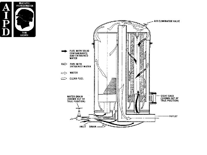
PART A – SUPERVISING THE USE OF FILTER/SEPARATORS Filter/separators (Figures. 1 -1) remove solid contaminants and entrained water from liquid fuels. Filter/separators range in size from 15 GPM to 600 GPM capacity. Organizational maintenance personnel are responsible (with the help of the equipment operators) for replacing the filter elements in all filter/separators. The use of standard interchangeable elements and canisters make it simple to replace elements in filter/separators. They may be used when ground products, such as automotive gasoline and diesel fuel, are pumped to the user’s vehicles. They must be used on all lines pumping fuel directly to aircraft and to vehicles that refuel aircraft. In addition, all fuel loaded into aircraft refueling vehicles should be filtered again before it is pumped to aircraft.
The standard filter element fits inside the canister. It is a perforated tube surrounded by a fiberglass filtering material which, in turn, is wrapped with several layers of different material. The fiberglass material filters solid particles from fuel. The outside of the element consists of layers of fiberglass, acetate, cotton knit, and fiberglass screen. This part coalesces (combines) fine particles of water in the fuel to form water droplets, which settle because they are heavier than fuel. The service life of a standard filter element is 24 months. The canister is a cylinder approximately 5 inches in diameter and 23 inches long. It consists of an outer and inner tube. The inner tube is made of perforated metal and metal screen. The outer tube is made of perforated metal lined with a Teflon coated screen.
Raw fuel enters the center tube of the filter element through a fitting at the bottom of the canister. Solid contaminants are removed as the fuel flows outward from the perforated center tube and through the fiberglass filtering material. As the fuel passes through the outer layers of the element, fine particles of water in the fuel are coalesced into droplets. The fuel containing the coalesced water passes through the inner tube of the canister to the space between the inner and outer tubes. The Teflon coated screen of the outer tube throws off water droplets, and they fall to the bottom chamber of the filter/separator. Only clean fuel passes through the outer canister tube into the filter/separator tank. Tank vehicles such as the M 131 A 5 C, M 969, and M 970 tank semitrailers have filter/separators that work in three stages. The first stage has 15 filter elements that remove solid contaminants. The second stage has five canisters to separate water from fuel and let water drain into the sump. The third stage has 15 go/no go fuses. They shut off the flow of fuel if the other two stages allow water or contaminants to exceed a safe level. M 49 A 2 C filter/separators have three filter elements, three separator canisters, and three go/no go fuses. The go/no go fuses automatically shut off the flow of fuel if the water and/or contaminants reach a high level.
Different Sizes of Filter/separators. �� 15 -GPM liquid fuel filter/separator is a vertical, portable unit consisting of an aluminum tank mounted on an aluminum skid. This tank has fuel inlet and outlet valves, a water drain valve, and a water level sight gage. The pressure vent valve’s working pressure is 25 psi. The 15 -GPM filter/separator is used with the 15 -GPM hand operated dispensing pump. �� 50 -GPM filter/separator consists of an aluminum tank with removable cover, inlet pipe with dust plug, outlet pipe with dust cap, water drain valve, an air vent valve, a pressure differential indicator, sight glass, four elements, and a canister. A reading in the green (0 -20 psi) means the elements are clean. A reading in the yellow (20 -A 35 psi) means the elements must be changed at the end of the day’s operations. A reading in the red (35 psi and up) means the elements must be changed at once. Maximum working pressure is 75 psi. It is used in refueling systems and for servicing ground vehicles. �� 100 -GPM filter/separator, aluminum pressure tank with removable head. The tank is welded in a tubular aluminum frame. Maximum working pressure is 75 psi. �� The 350 -GPM filter/separator is used in 150 psi airfield refueling systems, motor fuel servicing equipment, military hoseline systems, and as a component of the FSSP.
PART B - SUPERVISING FILTER/SEPARATOR PMCS Supervising Before Operation Maintenance. �� Ensure a visual check is made for leaks and for loose or missing parts in the cover assembly and other connections. �� Ensure that all valves operate freely and do not leak. Ensure drain valves are in closed position. �� Ensure the ground wire is connected properly and is not broken. �� Ensure gaskets are in place and not leaking. �� Ensure that fire extinguishers are accessible and in good working order
Supervising During Operation Maintenance. �� Ensure personnel check pressure gage reading to ensure pressure reading is below the red band on the gage. If it is in the yellow band, change elements after the operation. (If in the red, stop operation. ) �� Ensure personnel check water level sight gage and drain water if necessary. �� Ensure personnel check the filter/separator for leaks. Supervising After-Operation Maintenance. �� Ensure that personnel clean and store the equipment. �� Ensure all dust caps and plugs are installed after the operation.
LESSON 2 DIRECT THE USE OF PUMPS
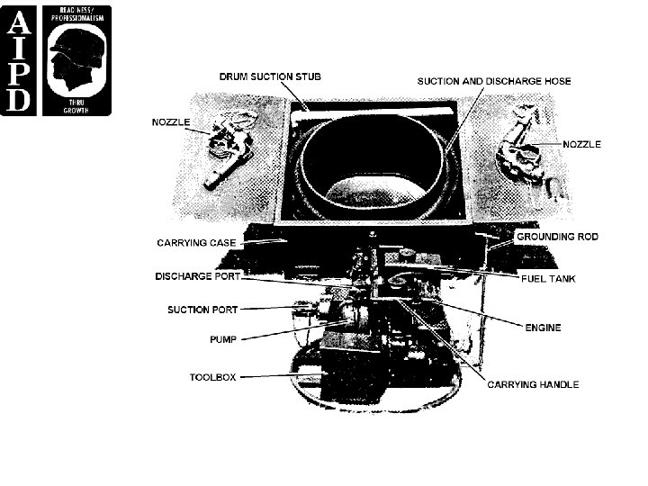
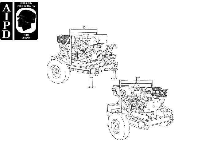
PART A - DIFFERENT TYPES OF PUMPS AND THEIR CHARACTERISTICS The 50 GPM pumping assembly (Figures 2 -1) consists of a pump and engine assembly mounted on an oval aluminum base. A one cylinder, four-cycle, aircooled, gasoline engine is used to power the pump. The pump is a self-priming centrifugal pump. The pump suction and discharge port has 1 1/2 -inch cam locking coupling adapters with dust caps.
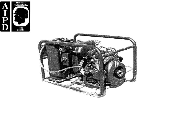
The 100 GPM pumping assembly (Figures 2 -2) is used as a component of the FARE system. An air cooled, one cylinder, gasoline-driven, four cycle engine is used to power the pump. It develops 2 1/2 horsepower at 3, 500 RPM. The 100 -GPM pumping assembly is used to transfer fuel from storage tanks, tank cars, and tank vehicles to smaller capacity containers
The 350 -GPM pumping assembly (Figures 2 -3) is used mainly with the fuel system supply point (FSSP). Towing Speeds. �� Hard surface - 20 MPH. �� Gravel road - 10 MPH. �� Rough cross country - 8 MPH. Gasoline Models (350 -GPM). �� Barnes Model, Idle speed 700 -800 RPMs, Normal operational speed 3, 200 -3, 600 RPM's. �� Gormann Rupp Model, Idle speed 1, 000 RPM's, Normal operational speed 2, 100 -2, 40
Diesel Models. The 350 -GPM pumping assembly is designed specifically to transfer gasoline, jet fuels, light liquid petroleum fuels, and water. It consists of an air cooled, three cylinder diesel engine and a self-priming centrifugal pump mounted on a two-wheel frame assembly. �� Model 1322021070 (97403). This model is used to transfer fuel only and does not have a regulator. It is manually controlled and has a recommend warm up and cool down time of two minutes. �� Model 13226 E 2289 (97403). This model is used to transfer fuel only and has a regulator that provides manual and automatic modes of operation. �� Model 13225 E 9200 (97403). This model is used to transfer water only and does not have a regula
PART B - VERIFYING PMCS ON PUMPS Supervising Before Operation Maintenance. �� Ensure fuel tank is filled if necessary and checked for secure mounting. �� Ensure air cleaner cup is checked for quantity and condition of oil. Service if necessary. �� Ensure fuel strainer bowl is checked for dirt and water. Service if necessary. �� Ensure fuel lines and fittings are free of leaks. Tighten fittings to correct leaks. �� Ensure oil level is checked. Add oil if necessary. �� Ensure engine and pump rotation is checked for free rotation. �� Ensure suction hose is checked for collapsed walls and signs of leaking. Replace a damaged hose. �� Ensure fire extinguishers are present and in working condition. �� Ensure chock blocks are used as appropriate. �� Ensure grounding rods are used as required.
Supervising During Operation Maintenance. �� Ensure personnel check discharge hose for leaking hose or fittings. Replace a damaged hose. �� Ensure personnel check hose nozzle for leaks and faulty operation. Supervising After Operation Maintenance. �� Ensure fuel tank is filled if necessary and checked for secure mounting. �� Ensure that personnel clean and store the equipment
LESSON 3 SUPERVISE PETROLEUM TANK VEHICLE OPERATIONS Critical Task: 101 -519 -4305
INTRODUCTION The use of the tank vehicles in the Army is increasing because of the need for larger volumes of bulk fuels and rapid, uninterrupted distribution requirements for refueling Army aircraft and vehicles. As a senior petroleum supply NCO you are responsible for being familiar with and ensuring that your personnel accomplish tank vehicle operations according to specified task performance measures. When controlling tank vehicle operations you must ensure that all fuel dispensing and receiving operations, environmental and safety considerations, quality surveillance, accountability, and security procedures are followed correctly. All tank vehicles come equipped with at least one fire extinguisher. It is important that you and your personnel become familiar with the location and use of the fire extinguishers supplied with the tank trucks you will be utilizing. As with any petroleum operation always ensure that fire extinguishers are inspected and serviced at required intervals.
PART A - TANK TRUCKS The Army utilizes several different tank vehicles for use in refueling operations. Below is a description of these vehicles and their typical uses. M 49 A 2 C Tank Truck. The M 49 A 2 C tank truck is mounted on a modified M 45 A 2 chassis (2 1/2 ton). The truck has a multi-fuel engine with single front and rear dual tires. It is about 23 feet long, 8 feet wide, and 7 2/3 feet high. TM 9 -2320 -209 -10 provides details on this truck. The tank body is a stainless steel 1, 200 gallon tank shell divided into two 600 -gallon compartments. Each compartment has a manhole cover. One 5 pound carbon dioxide fire extinguisher is mounted on the left and one is mounted on the right front of the vehicle. The rear equipment cabinet consists of a manifold, pump, filter/separator, discharge valve control and meter, water separator chamber, gage stick, grounding assembly, pump delivery line valve, gravity delivery line valve, filter/separator drain valve, and pressure gage. The pressure differential gage measures the effectiveness of the filter/separator. When the pressure differential between the inlet and outlet pressure is more than 20 psi, change the filter elements and the go/no go fuses. If pressure differential between the inlet and internal pressure is more than 15 psi, replace filter elements only. Change only the go/no go fuses when the pressure differential reading is 15 psi between the internal and outlet pressure. A power take off shifting lever is located in the cab to the left side of drivers seat. It operates the pump. The lever is moved backward to engage the pump. To disengage the pump, pull lever forward. The M 49 A 2 C is used for top and bottom loading, defueling aircraft, and pressure discharging.
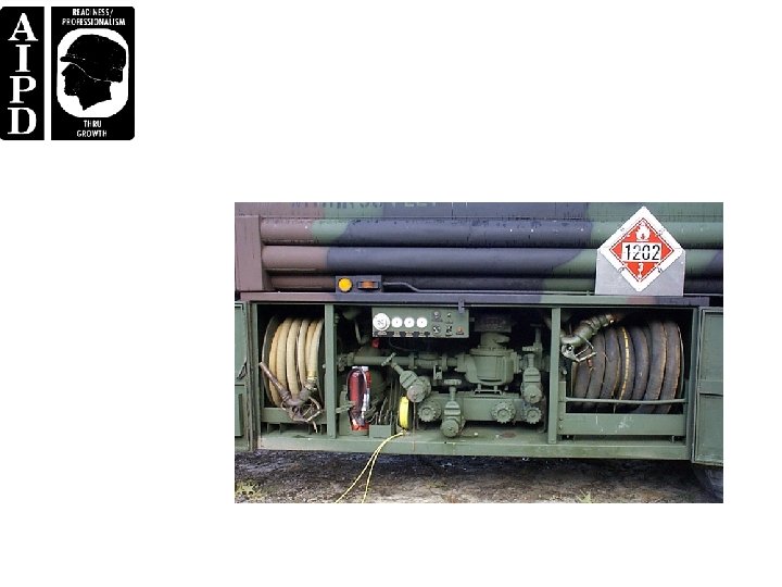
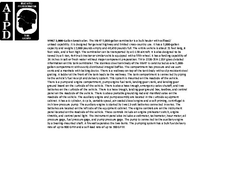
M 131 A 5 C 5, 000 -Gallon Semitrailer. The M 131 A 5 C semitrailer (Figures 3 -1 and 3 -2) has a 5, 000 gallon capacity and weighs 12 tons. The entire vehicle is about 31 feet long, 8 feet wide, and 9 feet high. It is towed by a 5 -ton, 6 x 6 tractor truck or like vehicle that has a fifth wheel. The semitrailer is used to carry and transfer fuel, service containers, and refuel ground vehicles and aircraft. The semitrailer can travel crosscountry at a reduced payload of 3, 300 gallons (1, 650 gallons in each tank compartment). It can fill or empty 3, 000 -, 10, 000 -, 20, 000 -, or 50, 000 -gallon collapsible tanks. The vehicle can transfer product to, or receive it from the fuel system supply point (FSSP). The stainless steel tank body is divided into two 2, 500 -gallon compartments, has a 20 -inch manhole and filler cover assembly, with a vent valve and locking device, a discharge valve with screw assembly, and a drain pipe. A full marker gage that indicates when the tank is full is welded to each manhole cover. There is a walkway on top of the tank body with a slip-resistant steel grating. A ladder at the rear of the vehicle gives access to the manhole covers. The two compartments are connected by piping to the vehicle’s fuel delivery system. There is one equipment cabinet and a filter/separator on the curbside of the vehicle. The curbside equipment cabinet houses an auxiliary engine, pump, and battery. There are three hose tubes and one equipment cabinet on the roadside of the vehicle. The roadside equipment cabinet houses a meter, a 1 1/2 -inch (0 -55 GPM) dispensing assembly, 2 1/2 -inch (225 GPM) dispensing assembly, filter/separator pressure gages, engine controls, fixed fire extinguisher system, portable fire extinguisher, and fuel handling controls. The three hose tubes are located directly above the roadside equipment cabinet. They hold three sections of suction hose and a gage stick. There is a door on both ends of the hose tubes. The auxiliary engine and pump assembly has a 2 -cylinder, 4 -cycle, air-cooled gasoline engine; a self-priming centrifugal pump; and a 24 -volt battery. The choke is on the left side of the engine. The engine controls are on the instrument panel located in the roadside equipment cabinet. These controls consist of a power panel switch, starter button, ignition switch, oil pressure gage, and voltage gage. The pump is connected to the auxiliary engine by a bearing-mounted shaft. A firewall separates the two items. The entire pumping system has a total capacity of 225 GPM. The filter/separator has three filtering stages. In
the first stage 15 filter elements remove solid contaminants and coalesce any water in the fuel. In the second stage, five canisters separate the water from the fuel and let it drain into the filter/separator sump. Finally, there are 15 go/no go fuses as safety devices to shut off the flow of fuel if the other two stages allow water or solid contaminants to exceed a safe level. There are three of these fuses in each of the second-stage canisters. Other parts of the filter/separator include an automatic dump valve, a manual drain valve, an emergency shutoff control, and three pressure gages. Any water collected in the filter/separator is removed by the automatic dump valve. This valve is operated by a float that rises in water and sinks in fuel. Drain water from the unit by opening the manual drain valve located at the bottom of the sump. Keep the valve open as long as water is running out. When fuel appears, close. While product is flowing through the separator, check the pressure differential. A 300 -GPM positive displacement meter is located on the right side of the roadside equipment cabinet. The meter counter registers up to 9, 999 gallons. A knob on the side of the meter is used to reset the counter. To do this, the knob is turned clockwise until the counter is back to zero. The meter also has a totalizer which keeps a record of all issues. There are three dispensing assemblies on the M 131 A 5 C tank semitrailer. One assembly is made up of three 15 -foot sections of 3 -inch suction hose. These sections are stored in tubes located on the roadside of the vehicle. The other two assemblies are housed in the roadside equipment cabinet. The on the left side of the cabinet is a 0 -55 GPM dispensing assembly. It has a 50 -foot section of 1 1/2 -inch discharge hose, a hose reel, and a 1 1/2 -inch nozzle with a bonding clip and a plug. The assembly on the right side of the cabinet is a 225 GPM dispensing assembly. It has a 50 -foot section of 2 1/2 -inch discharge hose, a hose reel and a 2 1/2 -inch nozzle with bonding clip and plug. The 2 1/2 -inch nozzle comes with two nozzle spouts. The standard 14 -inch spout, standard for most fueling operations is normally attached to the nozzle. The 24 -inch spout, used only for defueling operations, is stored on the left side of the fire extinguisher in the roadside equipment cabinet. Each dispensing assembly is controlled by a brake assembly and a rewind mechanism. There are two fusible link connections and two fusible nut connections on the semitrailer. Two fusible links are installed at the tank compartment discharge valves and two fusible nuts are part of the operating lever assembly. If there is a fire in any of these places, the fusible links and nuts melt and close the tank compartment discharge valves.
M 967 5, 000 -Gallon Semitrailer. The M 967 5, 000 -gallon semitrailer is a bulk hauler with selfload/ unload capability. It is designed for general highway and limited cross-country use. It has a 5, 000 -gallon capacity and weighs 13, 000 pounds empty and 46, 950 pounds full. The entire vehicle is about 31 feet long, 8 feet wide, and 9 feet high. The semitrailer can be transported by a C-130 aircraft. It is also designed to be towed by a 5 -ton, 6 x 6 truck tractor or similar vehicle equipped with a fifth wheel. It has a fording capability of 24 inches in salt or fresh water without major component preparation. TM 9 -2320 -356 -12&P gives detailed information on this tank semitrailer. The stainless steel tank body of the M 967 is constructed as one 5, 000 gallon compartment with evenly distributed integral baffles. The compartment has pressure and vacuum vents and a manhole with locking device. There is a walkway on top of the tank body with a slip-resistant steel grating. A ladder at the front of the tank leads to the walkway. The tank compartment is connected by piping to the vehicle’s fuel receipt and delivery system. This system is mounted on the roadside of the vehicle. There is a pump and engine compartment, pump engine fuel tank, landing gear crank, and landing gear ground board on the curbside of the vehicle. There is also a hose trough, emergency valve shutoff, and two batteries on the curbside of the vehicle. There is a hose trough, landing gear ground box, toolbox, and control panel on the roadside of the vehicle. There is also a portable grounding rod and manifold valve on the roadside of the vehicle. The auxiliary engine and pump assembly are located in the curbside equipment cabinet. It has a 4 -cylinder, 4 -cycle, variable speed, air-cooled diesel engine and a self-priming, centrifugal 4 inch low-pressure pump. The auxiliary engine is started by two 12 -volt batteries connected in series. The batteries are located on the left side of the equipment cabinet. The engine controls are on the instrument panel located on the roadside of the vehicle. These controls include an engine preheater switch, engine throttle, and control panel light. The instrument panel also includes a voltmeter, tachometer, hour meter, oil pressure gage, fuel pressure gage, and pump pressure gage. The pump is connected to the auxiliary engine by a bearing-mounted shaft. A firewall separates the two items. The pumping system has a bulk fuel delivery rate of up to 600 GPM and a self-load rate of up to 300 GPM.
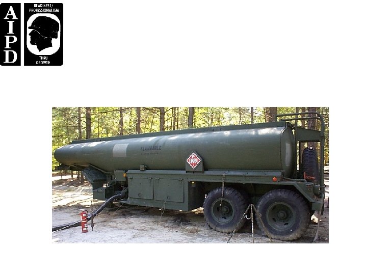
M 969 5, 000 -Gallon Semitrailer. The M 969 5000 -gallon semitrailer (Figure 3 -3) is a fuel-dispensing semitrailer used primarily for refueling ground vehicles. The M 969 has the same bulk delivery and self-load capabilities as the M 967. It has a 5000 -gallon capacity and weighs 15, 000 pounds empty and 48, 950 pounds full. The M 969 has the same dimensions and can be towed and transported in the same manner as the M 967 tank semitrailer. The tank body and auxiliary engine and pump assembly are identical to that of the M 967. TM 9 -2320 -356 -12&P gives detailed information on this tank semitrailer. In addition to the equipment included with the M 967, the M 969 includes equipment required for automotive refueling and limited aircraft refueling. This equipment is mounted on the sides of the vehicle. There is a filter/separator, pump and engine
compartment, engine fuel tank, landing gear crank, and landing gear ground board on the curbside of the vehicle. There is also an emergency valve shutoff, hose trough, and battery compartment for two batteries on the curbside of the vehicle. There is a hose trough, portable grounding rod, landing gear ground board, toolbox, control panel, manifold assembly, and hose reel cabinet on the roadside of the vehicle. The filter/separator is rated at 300 GPM and 150 psi. It has three filtering stages. In the first stage, 15 -filter elements remove solid particles and coalesce any water in the fuel. In the second stage, five canisters separate the water from the fuel and let it drain into the filter/separator sump. Finally, 15 go/no go fuses act as safety devices to shut off the flow of fuel if the other two stages allow water to exceed a safe level. Three of these fuses are in each of the second stage elements. Other parts of the filter/separator include an automatic drain valve, a manual drain valve, and a pressure gage. When water in the filter sump reaches a certain level, the water is removed by the automatic drain valve. This valve is operated by a float which rises in water and sinks in fuel. As water enters the filter sump the float rises. When the float rises to a certain level, a valve opens in the drain valve assembly allowing pump pressure to be applied to a diaphragm valve. The opening of diaphragm valves causes the automatic drain valve to open, allowing the water to drain. As the water is being drained, fuel flow is continued. If water enters the sump faster than the automatic drain valve can carry it away, or if the filter elements fail, the go/no go fuses stop the flow of fuel completely. The pressure gage is located on the instrument panel in the roadside equipment cabinet. It indicates the amount of restriction in the filter/separator. Two 100 -GPM meters are located in the roadside equipment cabinet of the M 969. The meter counter registers up to 9, 999 gallons. To reset the count to zero, push in the meter reset knob on the side of the meter and turn clockwise. The meter may also be used during defueling operations. If any trouble with the meter occurs, take the vehicle to organizational maintenance. The meter must also be checked for accuracy to make sure the correct amount of fuel is being delivered. There are three dispensing assemblies on the M 969 tank semitrailer. One assembly is made up of three 14 -foot sections of 4 -inch suction hose. These sections are stored in troughs located on both sides of the vehicle. This assembly has a bulk deliver rate of up to 600 -GPM and a self-load rate of up to 300 -GPM. The other two assemblies are housed in the roadside equipment cabinet. Each of these dispensing assemblies includes a meter, a hose reel with electric rewind, 50 feet of 1 1/4 -inch dispensing hose, and a dispensing nozzle. Flow rate for metered (4 -inch, low pressure control panel) delivery of fuel (gasoline or diesel) is up to 100 -GPM, through one nozzle only or through both nozzles at the same time
M 970 5, 000 -Gallon Semitrailer. The M 970 5, 000 -gallon semitrailer (Figure 3 -4) is a fuel dispensing, recirculating semitrailer, used primarily for under-wing/overwing refueling of aircraft. It has a 5, 000 -gallon capacity and weighs 15, 200 pounds empty and 49, 150 pounds full. The M 970 has a bulk delivery rate up to 600 GPM and a self-load rate up to 300 -GPM. The M 970 is designed to be towed by a 5 -ton, 6 x 6 truck or similar vehicle equipped with a fifth wheel. The tank body is stainless steel and is constructed as one 5, 000 gallon compartment with evenly distributed integral baffles. The compartment has pressure and vacuum vents and a manhole with locking device. The tank compartment is connected by piping to the vehicle’s fuel receipt and delivery system. In the curbside cabinet, there is a filter/separator, two 12 -volt batteries, pump and
engine compartment, engine fuel tank, landing gear control, and emergency shutoff valve. The roadside cabinet houses the landing gear ground board, recirculation fitting, portable grounding rod, toolbox, manifold assembly, control and instrument panel, hose reel cabinet. In the hose reel cabinet, you have a 1 1/2 -inch hose reel and hose, a 2 1/2 -inch hose and reel and hose, and a 300 -GPM meter assembly (3 inch, high pressure control panel).
M 978 HEMTT Tanker. The M 978 HEMTT tanker (Figure 3 -5) is used for refueling wheeled and track vehicles and aircraft which, on today’s modern battlefield, are mobile than ever before. The M 978 comes equipped with two hose reels, each containing 50 feet of 1 1/2” hose, with service nozzle of 2 1/2” in diameter, and a pressure differential gage, which indicates a dirty or clean filter/separator. There are 15 elements and 15 canisters. The vehicle can operate in temperatures from 25 to 120 degrees Farenheit, ford water up to 48 inches deep; for 5 minutes without damage, or maintenance before operation can continue. Maintains a speed of 25 MPH, on a 3 percent grade, with a full trailer (100, 000 lbs) and 40 MPH on a 3 percent grade vehicle only (60, 000 lbs). Maintain a speed of up to 55 MPH while operating at full load without a trailer on a good, level road. It can start and climb a 30 percent grade fully loaded with a trailer or start and climb a 60 percent grade fully loaded without a trailer. The normal operating range for this eight-wheel drive vehicle is 300 miles, based on 159 gallons of fuel. The M 978 can be utilized for self-loading (filtered or nonfiltered), recirculation, bulk delivery, filtered dispensing (using over wing/CCR nozzle), and defueling. The 300 GPM pump assembly operates by PTO and HACV. The M 978 is also supplied with a 25 GPM auxiliary pump that is powered by a 24 volt battery. The M 978 can also be used for aircraft refueling operations by utilizing the HEMTT Tanker Aircraft Refueling System (HTARS). The HTARS kit, it’s components, use, and operation are discussed in the following lesson.
Vapor Recovery System. The vapor recovery system can be installed on all models of tank semitrailers, and is required in certain ecological areas. The system allows a fuel depot to collect or recover the vapors and gases that are present during the loading operation. Vapors can also be recycled back to the semitrailer through the recovery system during the loading operation. This system consists of a vapor-tight line running from the sealed hood on the emergency valve vent (directly behind the manhole cover) to the rear of the tank. The rollover rail on the roadside of the semitrailer is used as part of the line. The adapter on the end of the line is compatible with the 4 -inch quick-disconnect, vapor recovery connections at a majority of fuel depots.
Tank and Pump Unit. The tank and pump unit consists of a 50 GPM pumping assembly, two 600 -gallon aluminum tanks, and related equipment. The unit is designed to be transported on the 5 -ton, 6 X 6 cargo truck, due to the fact that when the unit is filled with fuel it exceeds the load limit of the 2 ½-ton cargo truck. The unit can be used to fill and empty 500 -gallon collapsible drums, 55 gallon drums, and 5 -gallon cans; temporarily store product; refuel ground vehicles; and replace or supplement special-purpose vehicles. The unit may also be used to fuel aircraft if no other aircraft refueling equipment is available. There are several standard models of the tank and pump unit. The main differences are in their pumps, filter/separators, manifolds, and hoses. TM 10 -4930 -204 -15 (Operator's Maintenance Manual for Tank and Pump Unit M 978) gives details on installing, operating, and maintaining the different models of the unit. A description of the various components is provided as follows:
Tanks. The tank shells have a manhole assembly, pump-port drain plug, and discharge valve assembly. Controls for the discharge valve are on the top of the tanks. The discharge valve outlet is at the bottom rear of the tank, and the drain plug is at the bottom front. A baffle inside the shell helps keep down the surge of product during transport. Two lifting rings are attached to the top of each end of the shell to make handling easier. Tie downs are provided for securing the tanks in the vehicle bed. Pump. The pump is a 50 -GPM, self-priming, centrifugal pump. The impeller is screwed on the extension of the engine crankshaft. The engine is a 1 -cylinder, 4 -cycle, air-cooled, hand cranked engine. Some models have 2 -cylinder, 4 -cycle, overhead-valve, air-cooled engines. A radio-shielded magneto supplies the ignition spark, and a governor controls the engine speed by varying throttle openings to suit pump loads. The gasoline tanks hold one gallon. The pump and engine are mounted on a common base so that they can be easily removed for servicing and can be used in other pumping operations. Filter/separator. The filter/separator is a vertical, 50 -GPM capacity unit with four standard canisters and filter elements. The tank and pump unit can be used to refuel aircraft because the filter/separator qualifies under military aircraft refueling specificatio
Manifold. The manifold controls the flow of product to the suction side of the pump. Two quick couplers provide connections or inlets for the tank suction lines. The product flows from either or both tanks to the pump suction through the manifold outlet and a section of hose. Some models have a discharge hose that QM 5098 3 -8 runs from the filter/separator to the manifold, and product can be discharged from the manifold outlet when the three-way valve issued to close off the suction side. Other models use the only manifold for suction. Hose reels. The dispensing hoses are stored on two hose reels, each with a recoil tension spring. A 40 -foot length of 1 1/2 -inch, noncollapsible discharge hose is used on each reel. Product from the filter/separator enters through a pipe at the hub of the reel and is discharged through the hoses. Ground reel. A ground reel is attached to the frame of the pumping assembly so that the tank and pump unit can be grounded. One section of the ground wire must be clipped to a ground rod near the tank and pump unit before the other section is connected to the vehicle being fueled
Metering kit. The metering kit consists of a meter, hose assembly, couplers, cap screws, and washers. The kit is used with pumping assemblies on all tank and pump units. Other items issued with the pumping assembly are a drum-unloaded suction stub for emptying 55 -gallon drums, two dispensing nozzles, a starter rope, a carbon dioxide fire extinguisher, and tie down assemblies. If the nozzles have lock-on, latchopen devices, the devices must be fixed so that they must be held open by hand attended at all times.
PART B - GAGING PETROLEUM TANK VEHICLES Each tank has its own gage stick, which is graduated in 25 -gallon divisions. It may be made of wood or metal depending on the type of vehicle. The only difference in use between this stick and the petroleum gage stick is that the product cut will be recorded in gallons. It is important that your personnel keep the stick protected from the elements whenever not in use. Personnel will need to estimate the indicated volume as closely as possible when the cut mark falls between the 25 -gallon divisions. The 5, 000 -gallon tank semitrailers have gage sticks marked at the top to show which scale to use for each tank compartment. Before gaging any type of vehicle, the vehicle must be on level ground, and you must ensure that personnel bond and ground the tank vehicle and ground themselves from static electricity by touching a bare hand to the tank shell. Personnel should not wear loose items when they are on top of the tank vehicles. Personnel should never gage during an electric storm. Personnel should position the fire extinguisher within 10 to 15 feet of the tank vehicle. Verify the shipping document for the kind of fuel in the tank vehicle. Personnel should insert thermometer as soon as they open the hatch. (If quantity is less than 3, 500 gallons, it is not necessary to take the temperature. ) Personnel should gage the compartment and take an all-levels sample. Ensure that personnel measure the API gravity of the sample and record it on the gage work sheet. Personnel should correct the volume to 60 degrees Fahrenheit when required.
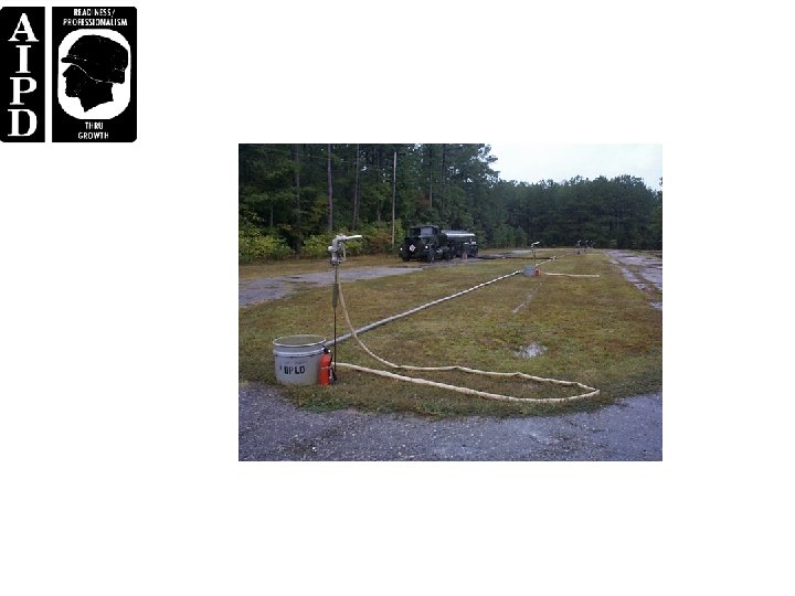
PART C - REFUEL-ON-THE-MOVE CONCEPT The "doctrinal purpose" of ROM is to extend the time that ground maneuver forces can spend on the objective, although ROM can be tailored to other situations as well. Refuel-on-the-move (ROM) for ground vehicles is synonymous with rapid or hot refueling for aircraft. ROM is normally accomplished as far forward on the battlefield as the tactical situation permits, prior to the tactical assembly area. When vehicles enter a ROM site (Figures. 3 -7) for refueling, they receive a predetermined amount of fuel (usually timed) and move out to return to their convoy or formation. This distinguishes it from routine convoy refueling operations. The manner in which this refueling is done depends upon the tactical situation. Each refueling operation is unique depending on the number of vehicles to be refueled, the distance the unit is traveling, and how many times the unit wants to be refueled. However, the assembly and operation of each ROM are basically the same. Due to safety considerations, normal vehicle refueling is done with engines off.
PART D - COMPONENTS OF THE ROM The following components make up the ROM kit : NSN NA 3 each, 14’ X 4’ suction hose 4720 -00 -083 -0048 8 each, 50’ X 3’ discharge hose 4720 -00 -555 -8325 8 each, 25’ X 1 1/2’ refueling hose 4730 -00 -075 -2405 1 each, 4’ X 4’ tee assembly 4730 -01 -096 -1039 8 each, 3’ X 1 1/2’ tee assembly 4930 -00 -471 -0288 8 each, 1 1/2’ nozzle 4730 -00 -951 -3293 2 each, 4’ to 3’ reducer 4810 -01 -098 -4925 8 each, quick shut-off valve with 1 1/2” adapters 5975 -01 -050 -5707 8 each, grounding rod 4210 -00 -257 -5343 8 each fire extinguisher
PART E - ROM ENVIRONMENTAL AND SAFETY PROCEDURES Due to the nature of ROM missions, it is very important to remember that you are responsible for the performance of all safety and environmental measures involved with each operation. Because you will be dealing with “temporary and mobile” situations, the chances of a mishap could occur more frequently. At a minimum, be aware of the following considerations when involved with ROM operations: �� Enforce grounding and bonding procedures for fuel semitrailers, pumps, filter/separators and each refueling point. �� Make sure fuel handlers wear protective clothing (for example, standard combat uniforms, hearing protection, goggles, and gloves). With the exception of the standard uniform, other items are normally provided by the organization.
�� Locate fire extinguishers at each refueling point and source of fuel (but not so close that they cannot be reached in the event of a fire). �� Ensure that personnel place fuel drip pans at each refueling point and fuel source. When draining drip pans, observe fire, safety, and environmental precautions. �� Ensure the fuel spills procedures and equipment include, as a minimum, sorbents, shovels, and containers. An SOP should detail equipment and procedures for response in a field environment. Ensure that the SOP follows federal, state, and local requirements
PART F - ROM EQUIPMENT CONFIGURATION QM 5098 3 -10 ROM is a concept that is equipment independent. As long as the concept is followed, any number of current equipment configurations can be used to do a ROM operations can be employed anywhere on the battlefield where there is a need to rapidly refuel combat vehicles.
The ROM kit consists of enough hoses, valves, and fittings to refuel up to eight combat vehicles at the same time. The kit takes care of transporting the ROM. Any cargo vehicle with a payload capacity greater than 1. 5 tons can be used. The ROM weighs about 2, 900 pounds. It cannot be loaded on the fueltransporting semitrailer due to the weight limit of the semitrailer. The main fuel source is the 5, 000 -gallon fuel semitrailer (model 969 s and M 131 A 5 C) using onboard pump and filter/separator. The average flow rate at each of the eight nozzles, using the fuel semitrailer, is 35 GPM. The area to set up and operate the eight-point ROM kit is about 550 feet long by 150 feet wide. Multiple tankers can be connected to the ROM kit by means of a Y- or T-fitting and valves. One tanker will be dispensing fuels through the ROM to refuel vehicles. The remaining tanker is backup and ready to replace the issuing tanker when it is empty.
NOTE: If conducting multiple tanker operations, fuel should not be received into and dispensed out of the same tanker at the same time. This would only be possible through top loading, which is a safety hazard. As a tanker is emptied, the fuel dispensing source is transferred to the backup tanker by the resetting of the values at the Y and/or T. This will allow fuel issues to continue to the combat vehicles. Fuel semitrailers can be shuttled to and from the ROM site to maintain a fueling tanker on-site.
PART G - REFUELING OPERATIONS Site Selection and Signaling. As a petroleum supervisor, your primary responsibilities for planning a ROM mission and selecting a site are as follows: �� Planning status. �� ROM site personnel. �� Utilization of GPS. Develop a contingency plan that accounts for security problems, equipment failure, and movement of vehicles. Make sure that there is enough room on the site to move equipment. Make the most used of natural cover and concealment. When selecting a ROM site always consider the following safety and security factors: �� Mission. �� Enemy. �� Terrain. �� Troops. �� Time
Include a signal system to coordinate the operation. Use signals to start and stop refueling operations and coordinate the vehicle serials to and from the holding areas. Use the arm and hand signals or flags during the day. Long distances may require radio communications. At night or in low visibility conditions, use chemical light or flashlights for signals.
Vehicle Holding and Marshalling Areas Set up these areas at locations before and after the ROM site. Coordinate areas before the start of the operation. Use the first area (prior to the ROM site) to organize the march column into serials of vehicles equal to the number of refueling points available. Call the vehicles forward out of the holding area one serial at a time to move into position to receive the predetermined amount of fuel. When each serial has received its allotted fuel, it moves to the second holding area (after the ROM site). In the second holding area, organize the vehicles back into their convoy march elements or combat formations. Ensure that personnel set up, perform PMCS, operate, and retrieve the equipment used in the operation. Ensure safety (for example, grounding, bonding, fire extinguishers, no smoking signs, drip pans, and spill equipment are in place and personnel are familiar with procedures). Ensure personnel are familiar and equipped with operational control signals (flags, lights, radio) to be used. Man fuel nozzles to refuel vehicles when convoy personnel (assistant driver or commander) are not available to refuel their own vehicles. Drivers must always remain in their vehicles. Ensure vehicles safely enter and move through the ROM site and receive the prescribed amount of fuel.
Document the Quantity of Fuel Used. To document the quantity of fuel issued, use either DA Form 3643 (Daily Issues of Petroleum Products) or DA Form 2765 -1 (Request for Issue or Turn-In), depending on the situation.
PART H - INSPECTION OF RAIL CARS Cars are inspected for suitability of use, proper documentation, and security seals. Generally, a petroleum rail car has only one compartment; however, some have more than one compartment and can carry multiproducts. Cars are manufactured from different gages of steel depending on usage and may be equipped with heaters to liquefy highly viscous product. Typically each compartment has a bottom outlet. In the U. S. 5 inch outlets are standard; overseas 4 -inch outlets are standard. Each compartment has a dome through which the rail car may be loaded, unloaded, inspected, cleaned, and repaired. The dome provides room for expansion of product in the event of temperature rise and may be hinged and bolted or screwed on. The tank car is also equipped with a safety valve. The safety valve used on most tank cars consists of a poppet valve, spring-loaded to predetermined pressure. As pressure develops in the dome and increases to a point in excess of the pressure setting of the valve, the valve is forced off the valve seat, thereby permitting excess vapor to escape. When the pressure drops to a level equal to the valve setting, the spring closes the valve automatically.
PART I - LOADING AND UNLOADING OF RAIL TANK CARS The minimum distance from a tank car loading operation to a building should be 100 feet. A spur track or bypass should be provided for loading or unloading tank cars. Trackage should be level to maintain equal depth of product throughout the tank car compartments. Level trackage is necessary for accurate gaging of the tank and to prevent air from being trapped at one end of a tank when the tank is closed. The site should provide adequate drainage. Bond and ground the car with a minimum of four cables. Derails should be installed at the head of the siding to prevent other cars from backing into the siding during transfer operations. A metal derail is approximately 18 inches long; the forward or flat portion is about 6 inches long and the rear or wedge shaped portion, about 12 inches long. It is attached to the top of one rail of the track. The 6 inch portion lays flat on the track, and the wedge-shaped portion gradually elevates to a height of about 1 foot 1/4 inch to either stop or derail the first car of a train backing into the siding. Some derails, designed in a similar manner, are made of wood. Derails may also be installed at other locations to prevent cars from rolling into danger areas if the brakes are released accidentally or fail to hold. Where derails are provided, they must be set and locked or operated so that they furnish the protection intended.
PART J - LOADING/UNLOADING FACILITIES AND EQUIPMENT Where more than one filling point is used, loading racks should be spaced to allow several cars to be loaded at one time. Each filling point should be grounded and should be equipped with bonding cables for bonding the filling point to the tank car shell and to the track. A flexible hose long enough to reach the bottom of the tank should be connected to the outlet of the loading arm. An emergency valve should be located some distance from the rack so that the line can be cut off in case of fire at the loading rack. Loading racks may be supplied with product directly from bulk storage tanks or pipelines by gravity flow, or fixed or portable pumping units may be used to transfer product. A distribution manifold, consisting of necessary piping and valves, extends along the loading rack and provides outlets for loading and unloading several cars at one time. Flexible hose lengths should be provided to permit loading cars through the domes. Manifolds must be grounded and equipped with cable for bonding the manifold to the track and to the tank car. A standard car mover should be provided for spotting tank cars. Electrical equipment operating in the area, such as lights, switches, and motors, must be of explosion-proof construction and must be in good working condition. A wooden cone-shaped plug, suitable for plugging the bottom outlet of the tank car, should be available in case of an emergency. The pump assembly must be positioned a minimum of 50 feet away from rail car.
PART K - PRECAUTIONARY AND SAFETY MEASURES Place signs prohibiting smoking conspicuously about the area. Do not allow welding, matches, lighters, open flames of any kind, or lights, other than approved explosion-proof flashlights or lanterns, within 100 feet of the transfer operation. Coal-burning locomotives operating near the transfer area should be equipped with smokestacks and fire box screens. All loading and unloading equipment must be grounded and bonded. Position one CO 2 or foam fire extinguisher on the ground, the other on the loading rack. In addition “Tank Car Connected” signs will be posted and visible to all personnel in the vicinity of the operation.
PART L - PROCEDURES FOR LOADING TANK CARS Preparation for Loading. Sampling and gaging product to be transferred. Ensure personnel take a sample of product that is to be transferred to the tank car and inspect it visually to make sure that product has no unusual appearance. If the identity or quality of product is questionable, have the test performed to make sure that product meets specifications before starting the transfer operation. Gage the contents of supply tank and record data. Obtain a water cut from the supply tank measuring with water-indicating paste. If the water layer in the tank approaches the level of the tank outlet, drain water before transferring product. Inspect pumps, hose, loading racks, pipelines, and manifolds to see that they are clean, free of any contaminating product, and in good operating condition
Equipment preparation. When possible, personnel should use equipment exclusively for handling one product. If it is necessary to use the same equipment for handling several products, drain the equipment thoroughly of preceding product before introducing the new product into the line. See that track rails are properly bonded and grounded. Inspect cable connections to make sure that they are secure and make bare metal-to-metal contact. Position car so that there will be no unnecessary strain on hose connections. If loading rack is to be used, position car so that dome is opposite filling point. Set brakes and block wheels of the tank car to prevent movement and to ensure safety of connections during loading operations. Set and lock derails, if provided. Place warning signs and fire extinguishers as required. Attach a ground wire to the shell of the tank car and to the stake and saturate the ground around the stake with water to make sure that grounding is effective. If a loading rack or tank car manifold is to be used, bond it to the tank car shell and to the loading rack.
Tank preparation. Remove the dome cover and determine whether the tank car is suitable for receiving product. Make sure that the product last carried by the tank is the same as the product that is to be transferred to the tank. If the product differs the tank must be cleaned before it is released for filling. Inspect the interior of tank for cleanliness; if there is residue on the bottom of the tank, the tank must be rejected and cleaned before it can be filled. Look for any foreign objects, such as tools, bolts, or old tank car seals that may have fallen into the tank. Objects should be removed by authorized persons. Although some objects do not contaminate the product, they may damage valves. Inspect the interior and exterior of tank to make sure that there are no holes, cracks, or loose plates. Be sure that there are no leaks in tank. See that the tank is properly mounted to under frame and that the tank is safe and road worthy. Inspect the dome, dome cover, and safety valve to see that they are operable and in good condition. Make sure that the vent holes in the dome cover are open and free of dirt. See that outlet chamber has not been damaged.
Tank valve inspection. Make sure that the outlet valve closes and seals properly. Place a drainage tub underneath the outlet chamber to catch drainage. Open and close the outlet valve several times by operating the valve rod handle or hand wheel located inside dome. If valve does not close properly, the valve gasket should be replaced or the valve repaired. In an emergency, a tank car may be loaded without repairing the outlet valve; however, this condition must be reported so that personnel receiving the tank will know to unload through the dome. In cases like this, the car should be scheduled for repair as soon as possible. When the outlet valve is operating properly, close the valve. The drainage tub should remain underneath the outlet until the transfer operation is completed. When necessary, tank cars may be flushed with a small amount of the product to be loaded. This is done to remove the last traces of previous product, as well as any rust and scale from the outlet sump of the tank car. Before removing the bottom outlet cap make sure that the outlet valve is properly closed. With a tank car wrench, remove the bottom outlet cap. Allow any product trapped in outlet chamber to drain into drainage tub. If there is any residual product in the tank, open the outlet valve and allow
product to drain into tub. Close the outlet valve, but do not replace the outlet cap until the car is completely loaded. Dispose of any product collected in the drainage tub, and place tub in position to catch additional leakage.
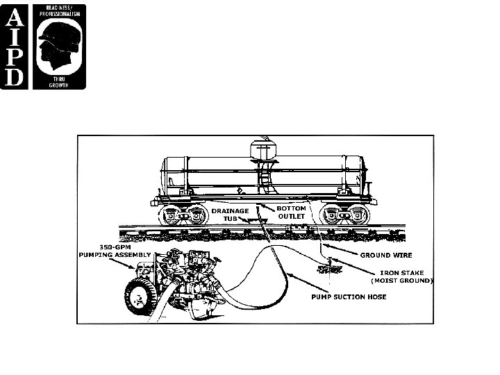
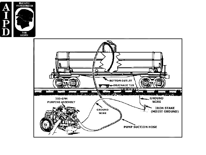
Loading Product. Tank cars should be loaded through the bottom outlet (Figure 3 -7) whenever possible to prevent vapor loss, reduce the generation of static electricity, and protect the fuel against contamination from outside sources. To bottom load a tank car, proceed as follows: Locate and ground a pumping assembly at least 50 feet away from the tank car. Make sure that the supply container is properly grounded and vented. Connect the hose lines, taking care to prevent hose connections from lying on the ground or from becoming otherwise contaminated. Station a man on the windward side of the dome to signal when the full mark is reached. Before starting the pump, open the appropriate valves to avoid pumping against a closed system. Start the pump and observe safety precautions. When the transfer operation is halted for any reason, disconnect the pump discharge hose. When the level of product in the tank car is near the full mark or bench mark, signal the pump operator to reduce the pump speed and be alert to stop the pump. When using a loading rack or other system that provides a control valve, reduce the flow of product into the tank by partially closing the valve. If the tank does not have a full mark, load the tank until the product reaches the top of the shell. When the product reaches the full mark or top of shell, shut down the pump, close all valves, and disconnect the pump discharge hose.
Top loading is done only in emergency situations when bottom loading is not possible and is accomplished by inserting the end of the loading hose or drop tube through the dome of the tank until it almost touches the bottom of the tank (Figure 3 -8). If the hose or drop tube does not extend far enough into the tank, the product splashes, causes undue loss of product through vaporization, and creates a potential fire hazard. Make sure that there is no unnecessary strain on the hose, which could cause the hose to move or come out of the tank during the transfer. Before starting the pump, open the appropriate valves to avoid pumping against a closed system. When all connections are secure and the necessary valves are open, start the pump. When product starts to flow into the tank, observe the bottom outlet to see if there is any leakage. If leakage is apparent, stop the pump and attempt to seat the bottom outlet valve by turning the valve rod handle in a clockwise direction. If the leak cannot be stopped, discontinue loading operations, recover product from the tank, and clear the area of spilled product. Follow safety precautions as given for bottom loading above.
Follow-Up Procedures. After loading the car, follow-up procedures are performed. Allow product to stand for 15 minutes so that suspended water or sediment can settle. Gage and sample contents of tank. Take temperature of product, correct volume to 60 degrees Fahrenheit, and record data. Retain sample for reference until car has been delivered. If tank contains any water or sediment, drain it from the tank, and again load product until the tank is full. After daily closing gages are taken, compare total storage tank issue with total quantities loaded on tank cars. Report excessive loss to proper authority. When tank car is full of product, replace bottom outlet and cap, and close and lock dome cover. Place an identification seal on the dome cover; it must be an approved seal, one which cannot be removed without being destroyed. The receiver is assured that the car has not been tampered with if the seal is in place. Record the seal marking on all shipping papers. Remove the drainage tub from under the bottom outlet, and discard any product that is in the tub. If the car has DANGEROUS-EMPTY placards, remove them and replace them with FLAMMABLE placards. Some placards bear the two signs; they only need to be reversed. Disconnect grounding wire from tank car; remove derails, if provided; and remove TANK CAR CONNECTED signs. Release brakes and remove car from transfer area.
PART M - PROCEDURES FOR UNLOADING TANK CARS Equipment preparation. Inspect the unloading equipment such as pumps, hose, loading racks, pipelines, and manifolds to see that they are clean, free of any contaminating product, and in good operating condition. When possible, use equipment exclusively for handling one product. If it is necessary to use the same equipment for handling several products, drain the equipment thoroughly of preceding product before introducing the new product into the line. If product in tank car is to be transferred to cans, drums, tank trucks, or semitrailers, inspect the containers or vehicle and make sure that they are clean and in good condition. If the product in the tank car is to be transferred to storage tanks, make sure that the tanks are clean and suitable for receiving the assigned product. If the tanks are not clean, they must be freed of vapors and cleaned before receiving product.
Sampling and gaging receiving tank. When a receiving tank already contains product, gage and sample the contents of tank. Take the temperature of the product, correct volume to 60 degrees Fahrenheit, and record data. Make sure that there is enough space (outage) in tank to receive product. Inspect sample visually to make sure product in receiving tank is the same as product in the tank car. If there is any doubt as to the identity or quality of the product, have the test performed to verify correct grade and quality before mixing new product with it. Drain water from the tank before starting transfer. Gage tank again and record data. Make sure that the receiving container and tank car are properly grounded and vented. Tank car inspection. Compare car number and seal number with numbers on shipping papers to see that the car to be unloaded is at the right destination. Examine seals and locks carefully for evidence of tampering. If cars arrive with broken seals or locks, notify the proper authority. If it is absolutely necessary that the car be released because of a shortage of tank cars, transfer the contents into a separate container, but do not use the product for any purpose until tested samples have been approved. Shortage of product should be made a matter of record. Pry seals loose and remove the dome cover. In hot weather, extremely high pressures may develop in tank cars if the safety valve is not functioning. When time permits, relieve pressure by permitting the car to cool overnight. If pressure is released by venting, large quantities of product are lost through vaporization, and a potential fire hazard exists. Inspect the tank car for leaks through the shell and bottom outlet. If the car shows evidence of leaking, schedule the car for immediate unloading. Place containers in position to catch leaking product.
Sampling and gaging tank car. Gage and sample contents of the tank car, and examine the sample for appearance and color. Take temperature of the product, correct the volume to 60 degrees Fahrenheit, and record data. Remove any water present in the tank by draining water slowly through the bottom outlet. If water is removed, gage contents again, correct volume to 60 degrees Fahrenheit, record data. Examine a sample of the product visually to make sure that the product is of proper grade. Fuel having a cloudy or decidedly “off color” appearance should be suspected of having some contamination. Any questionable product should be thoroughly tested to make sure that it meets specifications before it is unloaded
Tank car valve inspection. If the car is to be unloaded through the bottom outlet, make sure that the outlet chamber is in good condition and that the outlet valve is operating properly. The valve may become inoperable in cold weather because water in the tank is likely to settle and freeze around the outlet valve. To free frozen valves, apply steam jet, hot water, or hot cloths to outlet chamber. When authorized, a hot air, duct tent heater, or a slave kit may be used by trained personnel to thaw the outlet. If time permits, allow the valve to thaw during the warm part of the day.
Unloading tank car. �� To unload a tank car through the bottom outlet, locate the pump at least 50 feet from tank car and ground the pump. �� Make sure that the outlet valve is closed properly. �� Place a suitable drainage tub under the bottom outlet. �� The tub should remain under the outlet until the transfer operation is completed. �� Loosen the bottom outlet cap one or two turns to permit product trapped in the outlet chamber to drain out around the threads into the tub. �� If flow from the outlet does not slow down after approximately 15 minutes, attempt to seat the valve properly. �� If the valve cannot be closed, unload the tank car through the dome. Connect the pump suction line to the tank car outlet.
�� Connect the pump discharge line to the inlet of the receiving container. �� Dispose of drainage collected in the drainage tub, and again place the tub in position to catch any further leakage. �� Place the dome cover the manhole in such a way that air can enter the tank as product is unloaded. �� Place a block of wood under the edge of a hinged dome cover to ensure ample venting. �� When all connections are secure, open the bottom outlet valve. �� Open the necessary valves in the line to permit the free flow of product, and start the pump. �� As product starts to flow through the line, observe all connections to make sure that there are no leaks. �� If leaks are apparent, stop the pump and make necessary repairs or adjustments to stop the leaks before continuing. �� When all product has been unloaded from the tank, wait until the pump drains the suction line, and then shut down the pump
�� Close the inlet valve of the receiving container immediately after shutting down the pump so that product will not drain back into the line. Dome Unloading. To unload the tank car through the dome, locate the pump at least 50 feet from the tank car, and ground the pump. Place a drainage tub under the bottom outlet to catch any drainage. Insert the end of the unloading hose through the tank dome until it almost touches the bottom of the tank. Keep the hose below the surface of the product until the tank is completely unloaded. Connect the pump discharge line to the inlet of the receiving container. Place the dome cover the manhole so that the cover rests against the hose and allows ample space for venting. Follow pumping procedures described above. When the tank car is almost empty, manipulate the hose so that all product is drawn from the car. If possible, remove the bottom outlet cap and drain product from the outlet chamber into the tub.
Follow-Up Procedures. Make sure that the tank car is completely empty. Personnel should gage and sample contents of the receiving tank, correct volume to 60 degrees Fahrenheit, and record data. Compare the quantity of product delivered to the receiving tank with quantity taken from the tank car. Report excessive loss to the proper authority. Allow ample time for any suspended water and sediment to settle in the receiving tank, drain the water, gage the contents again, and record data. Close the bottom outlet valve. Remove the unloading hose from the tank car. If a wooden block is used to hold the dome cover open, be sure that the block does not fall into the tank car. Disconnect the tank car adapter and replace the outlet cap; tighten the cap with a tank car wrench. Close and lock the dome cover; remove the drainage tub and discard any product in the tub. If the car has FLAMMABLE placards, remove and replace them with DANGEROUS-EMPTY placards. Disconnect grounding wire from the tank car; remove derails, if provided; and remove TANK CAR CONNECTED signs. Release the brakes and remove the car from the transfer area. Notify the proper authority that the unloaded tank car is ready for removal and is being returned empty, free for load. Report any defective car to the property authority
PART N - CLEANING TANK RAIL CARS The two most common reasons for cleaning tank cars are contamination and change of product. Prior to beginning cleaning operations, appropriate safety measures must be taken. These include bonding and grounding the car and placement of safety signs and fire extinguishers. Personnel should clean uncoated tanks by steaming for one hour. If sludge remains, they should continue steaming until clean. On tank cars with multiple compartments, ensure that personnel clean one compartment at a time. Allow the tanks to cool, then check them with a explosimeter. Personnel should remove residual sludge and steam again with cleaning solvent. Allow the tank to cool then dry with lint-free rags. Never clean coated tanks with steam. Use air ejector or air eductor to vapor free the tank, check with explosimeter, then remove sludge. Personnel should scrub the tank with solvent, rinse with warm water and dry with lint-free rags.
LESSON 4 SUPERVISE AIRCRAFT REFUELING OPERATIONS
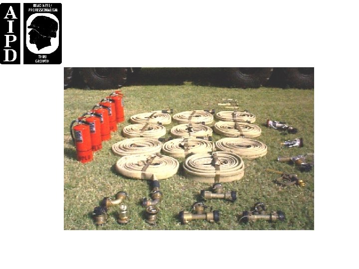
INTRODUCTION The HTARS is a kit that consists of enough hoses, fittings, and nozzles (Figure 4 -1) to expand the HEMMT tanker's capabilities to hot refuel up to four helicopters simultaneously using the on-board fuel-servicing pump. The equipment is lightweight, has manually operated controls, and is equipped with valved and swivel adapters that allow connections between camlock and unisex type fittings. This equipment can be used in forward areas. It can be transported in the storage box of the HEMTT tanker.
PART A - EQUIPMENT Discharge Hoses. The system consists of both 2 - and 3 -inch discharge hoses. One 3 -inch by 50 foot hose is used to connect the HTARS to the HEMTT tanker. Ten 2 -inch by 50 -foot discharge hoses transfer the fuel from the HEMTT tanker to the aircraft. Six hoses are used in the manifold and one in each of the four issue lines. There are 11 carrying straps for easy handling of rolled hoses.
Valves and Fittings. The following valves and fittings are components of the HTARS: �� Three T-connectors with a flow control handle to open and close the valve. The Tconnector splits the flow of fuel. �� Two elbow connectors to direct the flow of fuel. �� Three valved adapters to connect threaded and unisex parts as well as camlock and unisex parts. �� One swivel adapter to connect camlock and unisex part
Nozzles. The HTARS is equipped with four types of nozzles. There are four CCR nozzles with unisex adapters. Four overwing nozzles can be mated to the CCR nozzles to perform open-port refueling. The system has one recirculation nozzle that can be connected to the HEMTT tanker to recirculate fuel in the system. It is equipped with a fuel sample port to obtain a sample of fuel. The recirculation nozzle mates to the CCR nozzle. There are four D-1 nozzles to equip the system for center-point refueling.
Overpack And Other Required Items. Each system has one overpack spare with additional parts and accessories. The following parts are in the overpack spare: one T-connector, one 2 -inch by 50 -foot discharge hose, one carrying strap for easier handling of the rolled hoses, 10 dust seals, two dust caps, and four grounding rods. Other items of equipment are required to conduct aircraft refueling operations with the HTARS. A minimum of five fire extinguishers are required, one to be within reach of the onboard pump and one at each refueling point. Signs will need to be posted at the refueling site. Also, water cans and spill containers will need to be available.
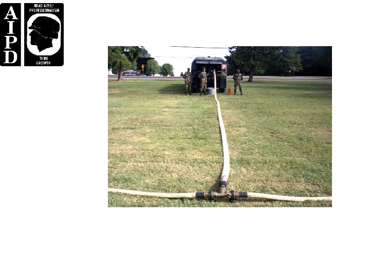
PART B - EQUIPMENT LAYOUT Ensure that personnel lay out the HTARS (Figure 4 -2) in a manner most practical for the situation. Avoid obstacles and take advantage of terrain features. When laying out the equipment, personnel should never remove a dust cap until ready to make a connection. This will prevent dust or particulate matter from entering the system and causing fuel contamination. Likewise, when disassembling, personnel should cap equipment immediately after uncoupling. When laying out the HTARS, follow the procedures below
Position Vehicle. Ensure that personnel select the most level ground to position the M 978 HEMTT tanker. Avoid areas near bodies of water to avoid contamination, and use the highest ground possible to prevent vapor accumulation. When positioning the vehicle, remember the system should be laid out so that helicopters can land refuel into a headwind or crosswind. Make the most use of natural concealment. Position the vehicle to allow easy exit without blocking exits. After positioning vehicle, drive a ground rod at least 3 feet into the ground, attach the vehicle ground cable to the ground rod, position fire extinguishers within easy reach, and post NO SMOKING signs
Connect System Components. Personnel should connect the 3 -inch by 50 -foot discharge hose to the suction hose on the HEMTT tanker (the tanker suction hose is connected to the bulk receptacle filter on the HEMTT tanker). Connect the T-to the 30 -inch discharge hose. Roll a 2 -inch by 50 -foot discharge hose from both sides of the T-and connect both discharge hoses to the T. Connect another T to the end of each 2 -inch discharge hose. Roll out and connect two 2 inch by 50 -foot discharge hoses to each outer "T". At the end of both outer 2 -inch discharge hoses, connect an elbow fitting. Unroll and connect a 2 -inch by 50 -foot discharge hose to each of the two Ts and elbow fittings. Put FLOW handles in flow position after connections are made. NOTE: The unisex fittings will not connect if the FLOW handles are in the flow position
Connect Nozzles. Personnel should connect the type of nozzle to be used for the operation to the 2 -inch discharge hose at each point. The CCR and D-1 nozzle connect to the 2 -inch discharge hose. The overwing (open-port) and recirculation nozzle mate to the outlet of the CCR nozzle. Refer to TM 54930 -235 -13&P (Operators Maintenance Manual for Closed Circuit Refueling Nozzle Assembly) for information on nozzles.
Ground Equipment. Personnel should drive a grounding rod into the ground 10 feet back from the end of each dispensing hose. Loop the dispensing hose at each point back to the ground rod and hang the nozzle on the ground rod hanger. Connect the clip of the nozzle grounding wire to the ground rod at each point. At each point, place a CO 2 or dry chemical fire extinguisher. Also, place a spill container and a filled 5 -gallon water can at each point.
Camouflage Equipment. Personnel should camouflage the truck and system to the extent required by the tactical situation. Natural concealment such as woodlines, hedgerows, vegetation, and natural terrain contours should be used when possible. Straight lines of the hoseline can be broken up by breaking branches and placing them under the hoseline to hold them in place.
PART C - OPERATION Preparation for Operation. Ensure all safety precautions have been taken. Verify that all safety and fire-Figurehting equipment is in place and serviceable. Check landing lights if they are required. Perform daily and before operations checks on the HEMTT tanker IAW TM 92320 -279 -10 -1 (Operators Manual for M 977 Series HEMTT) and on the HTARS TM 5 -4930 -237 -10 (Operator's Manual for HEMTT Tanker Aviation Refueling System (HTARS)). Inspect the discharge hoses, valves and fittings, nozzles, and grounding systems. Ensure that all refueling personnel have and are wearing the proper protective clothing. As soon as the system is full of fuel and ready to operate each day, draw a sample from each nozzle. The recirculation nozzle is equipped with a built-in fuel sample port. If the fuel does not pass tests and inspections, not use it. Isolate it, resample it, send the sample to the supporting laboratory, and await the laboratory’s instructions on disposition.
Sequence of Operations. The HTARS has two primary modes of operation, refuel and recirculation. In the refueling mode, fuel is pumped from the HEMTT tanker through the system hoses to the refueling points (nozzles). In the recirculation mode, the refueling nozzle (CCR or D-1) is disconnected from the refueling point and the recirculation nozzle is connected. The recirculation nozzle is connected to the HEMTT tanker and fuel circulates through the system hoses and back to the tanker. The HTARS can operate in both modes at the same time.
Refueling Mode. To operate the HTARS in the refueling mode, ensure that personnel follow these procedures: �� Start and operate the HEMTT tanker IAW TM 9 -2320 -279 -10 -1. �� Ensure the soldier manning the nozzle guides the aircraft into position using signals. Check with the pilot to be sure that all armaments are on SAFE. �� Deplane the crew and passengers. Passengers must go to the designated passenger marshaling area. Members of the crew, except the pilot or copilot who may remain at the controls if necessary, should deplane and assist with the refueling. Ensure that personnel man fire extinguishers at all times during refueling operations. �� Ensure the pilot notifies his commander that he will be off the air during refueling. He may monitor his radios during refueling, but he should never transmit. The crew chief and pilot may talk by intercom during refueling.
NOTE: Ground the aircraft. Grounding of aircraft during refueling is no longer required by NFPA standards 77 and 407. Grounding will not prevent sparking at the fuel surface. �� Bond the nozzle to the aircraft in one of two ways. Either insert the bonding plug into the plug receiver or attach the clip of the nozzle bonding cable to a bare metal part of the aircraft other than the antenna. 4 -5 QM 5098 �� After the nozzle is bonded to the aircraft, remove the dust cap from the nozzle and open the aircraft's fill port. �� Verify that all valves between the HEMTT tanker and the fuel nozzle are open. �� Do not leave the nozzle at any time during refueling. Stop the flow of fuel if there is any emergency at the refueling point. Three types of nozzles can be used for aircraft refueling. Use of the center-point (D- 1), CCR, and overwing (open-port) nozzle are described below
- Center-point refueling nozzle operation. Remove the dust cover from the end of the nozzle body. Grasp the handles and hold the nozzle in alignment with the aircraft refueling adapter. Press the nozzle body against the adapter and turn handles to the right until the end of the nozzle mates and locks to the aircraft refueling adapter. Rotate the control handle to the full OPEN position. The pilot will signal when the tank is full. To disconnect, rotate the control lever to the full CLOSED position. Grasp the handles and rotate the nozzle body to the left until it disconnects from the aircraft adapter. - CCR nozzle. Mate the CCR nozzle to the fill port. Pull back on the control handle latch, and then push the control handle up toward the aircraft into the FLOW position. If the aircraft is to be filled completely, watch the back of the nozzle. A red indicator will pop out of the back of the nozzle when the aircraft tank is full. Pull back on the flow control handle to move it into the NO FLOW position. Unlatch the nozzle.
- Overwing (open-port) nozzle. Rapid refueling (hot) using the open-port nozzle is restricted to combat or vital training (FM 10 -67 -1 (Concepts and Equipment of Petroleum Operation), Chapter 14). The decision to use the open-port nozzle must be made by the commander. The open-port nozzle is mated to the CCR nozzle. The end of the nozzle is placed in the aircraft fuel tank adapter. Set the CCR nozzle to FLOW. Squeeze the control handle to dispense fuel. Watch the fill port when filling the tank. As the tank nears full, ease up on the trigger and finish filling more slowly. When the tank is full, release the trigger. Move the flow control handle on the CCR nozzle to the NO FLOW position. Be sure that flow has stopped completely before removing the nozzle from the fill port.
�� Replace the cover of the aircraft fill port and put the dust cap back on the nozzle. �� Unplug the nozzle bonding plug or release the bonding clip. Carry the nozzle back to the hanger. Do not lay it or drag it across the ground. �� Release the grounding cable clip from the aircraft. �� Take the fire extinguisher back to a position near the nozzle hanger. �� Have the aircrew and passengers reboard the aircraft. �� Turn off the pump on the HEMTT tanker if no other aircraft is being refueled. �� After receiving clearance, the aircraft lifts off.
Recirculation Mode. One recirculation nozzle is supplied with the HTARS. To recirculate the entire system, the recirculation procedure must be performed for each refueling point. To perform recirculation, ensure that personnel follow the procedures listed below: �� Connect the recirculation nozzle to the refueling point (CCR nozzle). �� Reposition hoses as required to reach the HEMTT tanker. �� Connect the recirculation nozzle to the HEMTT tanker bottom loading receptacle A. Press the nozzle body against the A receptacle and turn the handles to the right until the nozzle body locks firmly to the receptacle. �� Start and operate the HEMTT tanker IAW TM 9 -2320 -279 -10 -1.
�� Set the CCR nozzle to OPEN. Rotate the recirculation nozzle control lever to the full OPEN position. �� If needed, fuel samples may be taken during the recirculation mode. The recirculation nozzle is equipped with a hand-operated ball valve to allow sampling of the fuel entering the tanker. To take the fuel sample, place the end of the tube in the sample container. Slowly move the control handle on the ball valve to the open position. When sampling is complete, set the control handle on the ball valve to the closed position. �� When recirculation is complete, set the recirculation nozzle control handle to the closed position. Set the CCR nozzle to the NO FLOW position. �� Shut down the HEMTT tanker IAW TM 92320 -279 -10 -1. �� Disconnect the recirculation nozzle from the HEMTT tanker.
LESSON 5 MANAGE WATERFRONT OPERATIONS Critical Task: 101 -519 -4307
INTRODUCTION More than half the tonnage handled in the military is petroleum. To do your job as a supervisor, you must know the responsibilities and procedures for loading and unloading petroleum tankers and barges.
PART A - TANKERS The Military Sealift Command-controlled tanker fleet provides worldwide transportation for the delivery of petroleum products from refineries to Department of Defense (DOD) storage facilities. The tanker fleet consists of approximately 30 tankers, which vary in size from 27, 000 to 38, 000 tons. The various types of lease contracts are as follows: �� Bareboat Charter - The tanker is leased to MSC, and MSC personnel crew the ship and are responsible for all expenses. �� Time Charter - From a few weeks to a number of years, the owner provides the crew and pays all expenses. �� Single Voyage Charter - The ship is leased for a single voyage, and the owner is responsible for the crew and all expenses.
�� Dirty Service - For heating oils and crude service. �� Clean Service - For finished products only. Ships cannot carry split cargoes without prior approval from the Defense Energy Support Center (DESC). When referring to various locations on a ship, or when describing certain conditions of the ship, the following terms are used: �� Bow - Front end of vessel �� Stern - Rear end of the vessel, also called the “aft section” �� Midships - Center of the vessel �� Port - The left side of the ship when standing midships and facing the bow. �� Starboard - The right side of the ship when standing midships and facing the bow. �� Bunkering - The fuel that is used to power the ship.
�� Gross Tonnage - The total internal cubic capacity of a vessel less exempted spaces, such as tanks for ballast water. This weight is expressed in units of 100 cubic feet per ton. �� Net Tonnage - The registered tonnage of a ship after deductions have been made from the gross tonnage. Examples of deductions are crew and navigation spaces. �� Light Displacement - The weight of the vessel. This does not include the weight of cargo, passengers, fuel, water, stores, and other items that are needed on a voyage. �� Loaded Displacement - The total weight of the vessel. This includes the weight of cargo, passengers, fuel, water, stores, and other items that are needed on a voyage. �� Deadweight Tonnage - The carrying capacity of a vessel in long tons (2, 240 pounds). It is the difference between light and loaded displacement
PART B - BARGES, PUMPS, TANKS, AND MANIFOLDS Barges. �� Self-propelled. These barges move under their own power and are used in inland coastal waterways. They must maintain a crew at all times. �� Non-self-propelled. They must be moved by tugboats and can be used for temporary storage. They are equipped with their own pumping systems. Pumps. Most tankers have two pumping systems. �� Centrifugal pumps for off loading the cargo. �� Gear or piston pumps for stripping the cargo tanks dry.
Ship’s Tanks and Manifolds. Most tankers have the capability to carry up to five different products. Ships' tanks are arranged abreast and numbered from bow to stern.
PART C - WATERFRONT FACILITIES �� Multileg mooring systems. �� Single-point mooring systems (mono buoy). �� Jetties: Jetties are used when the water depth or the shoreline is unsuitable for bringing in tankers. �� Docks and piers: Docks or piers (Figure 5 -1) are the most secure for unloading tankers. Security is easier to maintain. Access to the tanker is easier in case of emergency and for maintenance. They are protected from winds and tide and should be separated from other classes of supply. The depth should be at least 10 feet of water under the biggest tanker you expect to receive fully loaded at mean low tide
PART D - EQUIPMENT REQUIREMENTS �� Storage tanks. Minimum of two tanks for each product and ballast water. �� Oily water separator for treatment of ballast water. �� Fire fighting equipment. Portable fire extinguishers and an engineer fire Figurehting detachment. �� Pollution control equipment. Skimmer boats, absorbent materials, and containment booms. �� Communications has to be from the dock to the ship and to the tank farm. �� Transportation. Ground transportation and work boats for transporting men and equipment to the tanker. �� Grounding system. For bonding the ship to the dock. If the dock has a cathodic protection system it should be turned off before the transfer of fuel begins. �� Base laboratory. A lab should be available for testing the products.
PART E - PREPARATION FOR ARRIVAL The tanker arrival schedule is checked to ensure the type and quantity of product is known. Personnel are required to meet the tanker and go aboard in the harbor. A terminal representative, lab technician, and customs official may also be required. Make sure the berthing facilities are cleared for the tanker to tie up. QM 5098 5 -4 The cargo loading arms will be checked and maintenance performed. If cargo hoses are to be used, they will be pressure tested and the flanges checked. Shore tanks are gaged and sampled, and product is transferred to create ullage if required. All pipelines and manifolds are checked and packed with product to the dock. Maintenance is performed on all pumps, and all gages are checked. All communications are checked from the dock to the vessel and to the tank farm. Booms and skimmer boats are made ready to be deployed. Portable fire extinguishers are placed at all critical locations.
The terminal commander is responsible for all operations starting at the ship’s manifold: �� Pipeline patrol. �� Hose watch. �� Shift changes. �� The master of the vessel is responsible for all shipboard actions. Paperwork includes the tanker activity report and DD Form 250 -1 (Tanker/Barge Materiel Inspection and Receiving Report) (Figure 5 -2). The tanker activity report is issued as a worksheet to fill in DD Form 250 -1.
PART F - UNLOADING PROCEDURES Ensure that personnel follow these procedures: �� Valve seals. Prior to unloading, the valves aboard the vessel are checked to ensure they have been sealed and the seal numbers have been recorded on DD Form 250 -1. �� Pumping. For JP-4, pumping will commence at a reduced flow rate not to exceed three feet per second until the fill line in the tank is covered with fuel. �� Delays. Any delays will be recorded in the time section of DD Form 250 -1. This may determine who pays demurrage. �� Stripping. Once the centrifugal pumps lose suction, the stripper pumps are brought on line and the tanks are pumped dry
�� Completion of off loading. When the ships' tanks are empty, they are inspected by terminal personnel and a dry tank certificate is issued. If product is found in a tank and cannot be removed, the fact is recorded in the remarks section of the DD Form 250 -1. �� Gaging of shore tanks. After the proper settling time, the shore tanks are gaged and the amount is recorded on the DD Form 250 -1. If the amount received is less than that recorded on the DD Form 250 -1, and the shortage is more than one-half of one percent, it will require an investigation by the applicable DESC fuel region upon receipt of the DD Form 250 -1. For this reason, the inventories and submission of the paperwork must be done as soon as possible. �� Departure. After the tanker has departed, the pier is cleaned up and made ready for the next oper
PART G - LOADING PROCEDURES Ensure that personnel follow these procedures: �� As soon as the vessel is docked, the terminal chief should review the loading plans with the master of the vessel for US ports. This action will be mutually agreed upon. When loading at foreign ports, the vessel must first clear the foreign nation’s customs prior to performing any other procedure. �� Ensure that the vessel is properly grounded to the dock. �� Ballast. The shore ballast tanks should be checked to ensure that enough ullage is available to accept ballast from the tanker. �� Checking ship’s tanks. The ship’s tanks should be checked to ensure they are clean and free of ballast and suitable for receiving product. �� Pumping. Follow the same procedures as for unloading.
�� Follow up procedures. Allow enough time for tanks to settle before gaging each tank. Calculate the quantity loaded. �� Obtain an all-levels sample from each compartment and run a Type C test according to MIL-HDBK-200. �� Gage shore tanks and compare quantities pumped with quantities received. �� After the product quality and quantity have been determined, check and seal all hatches, seal valves and crossovers, and record all seal numbers on the DD Form 250 -1.