using ARM q Day 3 Simple RISC Assembly

嵌入式系統架構軟體設計 ---using ARM q Day #3 Simple RISC Assembly Language ARM Development Suite 使用練習 q Day #4 Arm Instruction set Important ASM Programming Skills ARM/THUMB/C Interworking q Day #5 ARM Exception Handler Build ARM ROM Image Use NET-Start! uc. Linux BSP 課程介紹

嵌入式系統架構軟體設計 ---using ARM q q q q q Steve Furber, ARM system-on-chip Architecture, 2 nd ed. Seal, ARM architecture reference manual, 2 nd ed. ARM Development Suite-Getting Started ARM Development Suite-Developer Guide ARM Development Suite-Assembler Guide http: //www. uclinux. org/ 2002嵌入式系統開發經驗 Building powerful platform with Windows CE Software Engineering, A practitioner’s Approach 3 rd ed. Professional Symbian Programming

嵌入式系統架構軟體設計 ---using ARM Module #3 -1: Simple RISC Assembly Concept

嵌入式系統架構軟體設計 ---using ARM Hardware instruction decode logic Pipeline execution Single -cycle execution A smaller die size A shorter development time A higher performance Poor code density RISC精简指令集vs. CISC复杂指令集 Large microcode ROMs to decode instruction Allow little pipeline Many cycles to completer a single instruction

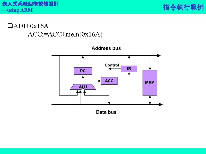
嵌入式系統架構軟體設計 ---using ARM 硬體單元 PC ACC ALU IR 功能 Program Counter Accumulator Arithmetic logic unit Instruction register MUO 一個簡單的處理器
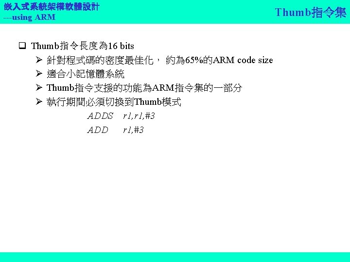
![嵌入式系統架構軟體設計 ---using ARM 指令規則 指令 Opcode 功能 LDA S 0000 ACC=mem[S] STO S 0001](http://slidetodoc.com/presentation_image_h/afab72fd2cf81a40fa642cede9d5af6c/image-8.jpg "嵌入式系統架構軟體設計 ---using ARM 指令規則 指令 Opcode 功能 LDA S 0000 ACC=mem[S] STO S 0001")
嵌入式系統架構軟體設計 ---using ARM 指令規則 指令 Opcode 功能 LDA S 0000 ACC=mem[S] STO S 0001 mem[S]=ACC ADD S 0010 ACC=ACC+mem[S] SUB S 0011 ACC=ACC-mem[S] JMP S 0100 PC=S JGE S 0101 If ACC>= PC=S JNE S 0110 If ACC!=0 PC=S STP 0111 stop MUO指令集與資料路徑
 { C=A+B; } MUO 機器指令 LDA ADD")
嵌入式系統架構軟體設計 ---using ARM 運算範例 C function: Main() { C=A+B; } MUO 機器指令 LDA ADD STO 0 x 100 0 x 104 0 x 108 指令 Opcode 功能 LDA S 0000 ACC=mem[S] STO S 0001 mem[S]=ACC ADD S 0010 ACC=ACC+mem[S] SUB S 0011 ACC=ACC-mem[S] JMP S 0100 PC=S JGE S 0101 If ACC>= PC=S JNE S 0110 If ACC!=0 PC=S STP 0111 stop

嵌入式系統架構軟體設計 ---using ARM 0 x 000 0 x 002 0 x 004 0 x 006 0 x 008 練習: MUO微處理器的運算 LDA 0 x 100 SUB 0 x 104 STO 0 x 100 JNE 0 x 000 STP 指令 請描述此段程式的動作,暫存器值的變化、 與資料流。請用C語言來寫出這段程式碼。 Opcode 功能 LDA S 0000 ACC=mem[S] STO S 0001 mem[S]=ACC ADD S 0010 ACC=ACC+mem[S] SUB S 0011 ACC=ACC-mem[S] JMP S 0100 PC=S JGE S 0101 If ACC>= PC=S JNE S 0110 If ACC!=0 PC=S STP 0111 stop

嵌入式系統架構軟體設計 ---using ARM Module #3 -2: ARM Assembly Language
")
嵌入式系統架構軟體設計 ---using ARM 7 TDMI資料流 e. g. r 3: =r 4+(r 4, , 2) ADD r 3, r 4, LSL#2 A bus B bus

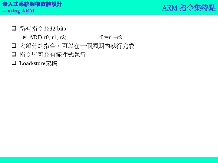
嵌入式系統架構軟體設計 ---using ARM 的暫存器 r 0 r 1 r 2 r 3 r 4 q 30 general-purpose, 32 bits registers q 1 Program Counter (PC) q 1 Current Program Status Register (CPSR) q 5 Saved Program Status Registers (SPSR) r 5 r 6 r 7 r 8 r 9 r 10 r 11 r 12 r 13 (sp) r 14 (lr) r 15 (pc) cpsr User mode FIQ mode irq mode SVC mode abort mode undefined mode

嵌入式系統架構軟體設計 ---using ARM Program Status Register q CPSR: Current Program Status Register q SPSR: Saved Program Status Register q Condition code flags N: Negative result from ALU Z: Zero result from ALU C: ALU operation Carried out V: ALU operation overflowed 31 30 29 28 27 24 N Z C V J Q q Interrupt Disable bits I: disable the IRQ F: Disable the FIQ undefined q T bit Architecture x. T only T=0: ARM state T=1: Thumb state 7 6 5 4 I F T mode q Q: Sticky Overflow flag Architecture 5 TE only QADD, QSUB… 0 q. Mode bits q. J: Processor in Jazelle state Architecture 5 TEJ only Specify the processor mode 10000 User 10001 FIQ 10010 IRQ 10011 SVC 10111 Abort 11011 Undef 11111 System

嵌入式系統架構軟體設計 ---using ARM Program Counter –R 15 q ARM state: All ARM instructions are four bytes long (one 32 -bit word) and are always aligned on a word boundary. The PC value is stored in bits [31: 2] with bits [1: 0] undefined. q In Thumb state: All instructions are 16 bits wide, and halfword aligned The PC value is stored in bits[31: 1] with bits [0] undefined. q In Jazelle state: All instructions are 8 bits wide. The processor performs a word access to read 4 instructions at once.

嵌入式系統架構軟體設計 ---using ARM Link Register –R 14 q Register 14 is the Link Register (LR). q This register holds the address of the next instruction after a Branch and Link (BL) instruction, which is the instruction used to make a subroutine call. q At all other times, R 14 can be used as a general-purpose register

嵌入式系統架構軟體設計 ---using ARM Other Register R 0 -R 13 q The remaining 15 registers have no special hardware purpose. q Their uses are defined purely by software. q By convention, ARM assembly language use R 13 as Stack Pointer. q C and C++ compilers always use R 14 as the Stack Pointer(SP).

嵌入式系統架構軟體設計 ---using ARM Structure of ARM Assembly Language Module AREA Sectionname{, attr}… Start of New code or data section. CODE: contain machine instructions. READONLY: section should not be written to. Other attr: DATA, NOINIT, READWRITE, … Declares an entry point to a program. Labels. Declares the end of the source file.

嵌入式系統架構軟體設計 ---using ARM Calling Subroutines Uses BL q BL destination • destination is the label on the first instruction of the subroutine. BL does: • place the return address in the link register (R 14) • sets PC to the address of the subroutine. In the subroutine • we can use “MOV pc, lr” to return. By convention, R 0 -R 3 are used to pass parameters.

嵌入式系統架構軟體設計 ---using ARM Calling Subroutines Example ; name this block of code ; mark first instruction ; to execute ; Set up parameters ; Call subroutine ; angel_SWI reason_report Exception ; ADP_Stopped_Application. Exit ; ARM semihosting SWI ; Subroutine code ; Return from subroutine. ; Mark end of file

嵌入式系統架構軟體設計 ---using ARM Constant Data Types q Numbers Numeric constants are accepted in three forms: • Decimal, for example, 123 • Hexadecimal, for example, 0 x 7 B • n_XXX where: • n is as base between 2 and 9 • xxx is a number in that base. q Boolean TRUE and FALSE must be written as {TRUE} and {FALSE}. q Characters constants consist of opening and closingle quotes ‘X’, enclosing either a single character or an escaped character, using the standard C escape characters. q Strings consist of opening and closing double quotes “XXXX”. If double quotes or dollar signs are used within a string as literal text characters, they must be represented by a pair of the appropriate character. For example, you must use $$ if you require a single $ in the string. The standard C escape sequences can be used within string constants.

嵌入式系統架構軟體設計 ---using ARM Conditional ARM Instructions q Almost all ARM instructions can be conditionally executed. e. g. ADDS ADDEQ r 0, r 1, r 2 q Execute if the N, Z, C and V flags in the CPSR satisfy a condition specified in the instruction, otherwise, NOP. 指令名稱 XXXCC 條件

嵌入式系統架構軟體設計 ---using ARM Conditional Execution q Almost every ARM instruction can be executed conditionally on the state of the ALU state flags in the CPSR. q Add an S suffix to an ARM data processing instruction to make it update the ALU state flags in the CPSR E. g. ADDS r 0, r 1, r 2 ; r 0= r 1+ r 2 and update ALU status in CPSR. q In ARM state, you can: update the ALU status flags in the PSR on the result of a data operation execute several other data operation without updating the flags execute following instructions or not, according to the state of the flags updated in the first operation. q In Thumb state most data operations always update the flags and conditional execution can only be achieved using the conditional branch instruction (B). q Do not use the S suffix with CMP, CMN, TST, or TEQ. These comparison instructions always update the flags.

嵌入式系統架構軟體設計 ---using ARM ALU Status Register in CPSR q N Set when the result of the operation was Negative. q Z Set when the result of the operation was Zero. q C when the result of the operation was Carry. A carry occurs if the result of an addition is greater than or equal to 232 If the result of a instruction is positive, or as the result of an inline barrel shifter operation in a move or logical instruction. q V Set when the operation caused o. Verflow. Overflow occurs if the result of an add, subtract, or compare is greater than or equal to 231, or less than – 231. q Q ARM architecture v 5 Eonly. Sticky flag. Used to detect saturation in special saturating arithmetic instructions (e. g. QAD, ASUB, QDADD, and QDSUB), Or overflow in certain multiply instructions (SMLAxy and SMLAWy)

嵌入式系統架構軟體設計 ---using ARM Conditional Code Suffixes

嵌入式系統架構軟體設計 ---using ARM q q ADD r 0, r 1, r 2 ADDS r 0, r 1, r 2 ADDCSS r 0, r 1, r 2 CMP r 0, r 1 Conditional Code Examples ; r 0 = r 1 + r 2, don’t update flags ; r 0 = r 1 + r 2, and update flags ; if C flag set then r 0 = r 1 + r 2, and update flags ; update flags based on r 0 -r 1. q Example code sequence: MOV R 0, #0 LOOP ADD R 0, #1 CMP R 0, #10 BNE LOOP SUB R 1, R 0

嵌入式系統架構軟體設計 ---using ARM Write Efficient and small size Code by Conditional Instruction

嵌入式系統架構軟體設計 ---using ARM Exercise Write program by ARM assembly, & evaluate the execution cost in clock. A Branch needs 3 cycles, others cost 1. 註:唯需透過CMP, SUB, B這 三個指令,加上條件式, 就 可以完成。 While (r 1!=r 2) do { if (r 1>r 2) r 1=r 1 -r 2; else r 2=r 2 -r 1; }

嵌入式系統架構軟體設計 ---using ARM Module #3 -3: ARM Development Suite使用練習

嵌入式系統架構軟體設計 ---using ARM Others: C & C++ Libraries ARM firmware suite AM application library Real. Monitor: for real time debug monitor ARM ADS 1. 2

嵌入式系統架構軟體設計 ---using ARM Implementation Integration by command line, makefile, Code. Warrior

嵌入式系統架構軟體設計 ---using ARM Pre-configured Project Stationary Files q Debug This build target is configured to built output binaries that are fully debuggable, at the expense of optimization. q Release This build target is configured to output binaries that are fully optimized, at the expense of debug information. q Debug. Rel This build target is configured to build output binaries that provide adequate optimization, and give a good debug view.

嵌入式系統架構軟體設計 ---using ARM Possible Development Environments

嵌入式系統架構軟體設計 ---using ARM q ARM Developer Suite Version 1. 2 Getting Started q 請依Chapter 3練習使用ADS。 Reference

嵌入式系統架構軟體設計 ---using ARM Module #3 -4: ARM Instruction Set

嵌入式系統架構軟體設計 ---using ARM q Branch instructions q Data-processing instructions q Load and store instructions q Status register transfer instructions q Coprocessor instructions q Exception-generating instructions. ARM指令集分類

嵌入式系統架構軟體設計 ---using ARM Branch Instructions q B Branch q BL Branch with link Store the return address to r 14 e. g. CMP r 2, #0 BLEQ function … MOV PC, r 14

嵌入式系統架構軟體設計 ---using ARM Branch Instruction Encoding Assembly Format: B{L}{<cond>}{S} Rm <Target address> q The range of the branch instruction is +/- 32 Mbytes q ‘L’: the branch and link variant.
 function 1 (1); Else… c")
嵌入式系統架構軟體設計 ---using ARM q e. g. C if (a=0) function 1 (1); Else… c function 1(){ function 2(); …} function 2(){ return; } Branch instructions example q. ASM function 1 STMFD BL … LDMFD function 2 … MOV r 13!, {r 0 -r 4, r 14} function 2 r 13!, {r 0 -r 4, pc} pc, r 14

嵌入式系統架構軟體設計 ---using ARM Data-processing Instructions Encoding Assembly Format: <op>{<cond>}{S} Rd, Rn, #<32 -bit immediate> <op>{<cond>}{S} Rd, Rn, Rm, {shift}
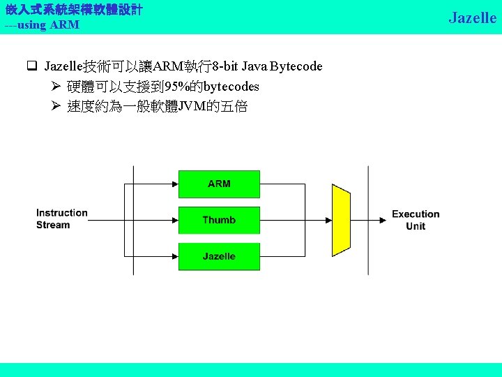
![嵌入式系統架構軟體設計 ---using ARM Data Processing Opcode Assembly Format: <op>{<cond>}{S} Opcode Mnemonic [24: 21] Rd,](http://slidetodoc.com/presentation_image_h/afab72fd2cf81a40fa642cede9d5af6c/image-45.jpg "嵌入式系統架構軟體設計 ---using ARM Data Processing Opcode Assembly Format: <op>{<cond>}{S} Opcode Mnemonic [24: 21] Rd,")
嵌入式系統架構軟體設計 ---using ARM Data Processing Opcode Assembly Format: <op>{<cond>}{S} Opcode Mnemonic [24: 21] Rd, Rn #<32 -bit immediate> Rd, Rn, Rm, {<shift>} Meaning Effect 0000 0001 0010 0011 0100 0101 0110 0111 1000 1001 1010 1011 1100 1101 1110 1111 Logical bit-wise AND Logical bit-wise excusive OR Subtract Reverse subtract Add with carry Subtract with carry Reverse subtract with carry Test equivalence Compare negated Logical bit-wise OR Move Bit clear Move negated AND EOR SUB RSB ADD ADC SBC RSC TST TEQ CMP CMN ORR MOV BIC MVN Rd: =Rn & Op 2 Rd: =Rn EOR Op 2 Rd: =Rn-Op 2 Rd: =Op 2 -Rn Rd: =Rn+Op 2+C Rd: =Rn-Op 2+C-1 Rd: = Op 2 -Rn+C-1 Scc on Rn&Op 2 Scc on Rn EOR Op 2 Scc on Rn-Op 2 Scc on Rn+Op 2 Rd: =Rn | Op 2 Rd: =Rn AND NOT Op 2 Rd: =NOT Op 2

嵌入式系統架構軟體設計 ---using ARM Example Data-processing Instructions q Arithmetic operations ADD r 0, r 1, r 2 SUB r 0, r 1, r 2 RSB r 0, r 1, r 2 ; r 0=r 1+r 2 ; r 0=r 1 -r 2 ; r 0=r 2 -r 1 q Bit-wise logical operations AND r 0, r 1, r 2 ORR r 0, r 1, r 2 EOR r 0, r 1, r 2 BIC r 0, r 1, r 2 ; r 0 = r 1&r 2 ; r 0 = r 1| r 2 ; r 0 = r 1 xor r 2 ; r 0 = and not r 2; bit clear
 q Register movement operations MOV r")
嵌入式系統架構軟體設計 ---using ARM Example Data-processing Instructions (cont. ) q Register movement operations MOV r 0, r 2 ; r 0=r 2 MVN r 0, r 2 ; r 0=not r 2 q Comparison operations (set condition code bits N, Z, C, V) CMP r 1, r 2 ; set cc on r 1 -r 2 q Immediate operands ADD r 3, #1 AND r 8, r 7, #&ff & : base 16 ; r 3=r 3+1 ; r 8=r 7[7: 0]
 q LSR: Logical Shift")
嵌入式系統架構軟體設計 ---using ARM q LSL: Logical Left Shift (X 2) q LSR: Logical Shift Right (/2) q ASR: Arithmetic Right Shift q ROR: Rotate Right Shifter

嵌入式系統架構軟體設計 ---using ARM e. g. #1 ADD r 3, r 2, r 1, LSL #3; r 3: = r 2+8*r 1 e. g. #2 r 0=r 1*5 r 0=r 1+(r 1*4) ADD r 0 , r 1, LSL #2 Shifter Applications

嵌入式系統架構軟體設計 ---using ARM Multiply Instruction Binary Encoding Assembly Format MUL{<cond>}{S} Rd, Rm, Rs MLA{<cond>}{S} Rd, Rm, Rs, Rn <mul>{<cond>}{S} Rd. Hi, Rd. Lo, Rm, Rs Rd. Hi: the most significant 32 bits of 64 -bit format number Rd. Lo: the least significant 32 bits of 64 -bit format number Opcode [23: 21] 000 001 Mnemonic Meaning Effect MUL MLA Multiply (32 -bit result) Multiply-accumulate (32 -bit result) Rd: =(Rm*Rs)[31: 0] Rd: =(Rm*Rs+Rn)[31: 0] 100 101 UMULL UMLAL Unsigned multiply long Unsigned multiply-accumulate long Rd. Hi: Rd. Lo: =Rm*Rs Rd. Hi: Rd. Lo+=Rm*Rs 110 111 SMULL SMLAL Signed multiply long Signed multiply-accumulate long Rd. Hi: Rd. Lo: =Rm*Rs Rd. Hi: Rd. Lo+=Rm*Rs
 Assembly Format: CLZ{<cond>}{S}")
嵌入式系統架構軟體設計 ---using ARM Count Leading Zeros Instruction (v 5 T only) Assembly Format: CLZ{<cond>}{S} Rd, Rm q Sets Rd to the number of the bit position of the most significant 1 in Rm. If Rm=0 Rd=32. q E. g. MOV r 0, #&100 CLZ r 1, R 0 r 1=8

嵌入式系統架構軟體設計 ---using ARM Assemble Format: LDR|STR{<cond>}{B} Single Word and Unsigned Byte Data Transfer Instruction Binary Encoding Rd, [Rn, <offset>]{!} Rd, [Rn], <offset> Rd, LABEL ; Pre-indexed form ; Post-indexed form ; PC-relative form
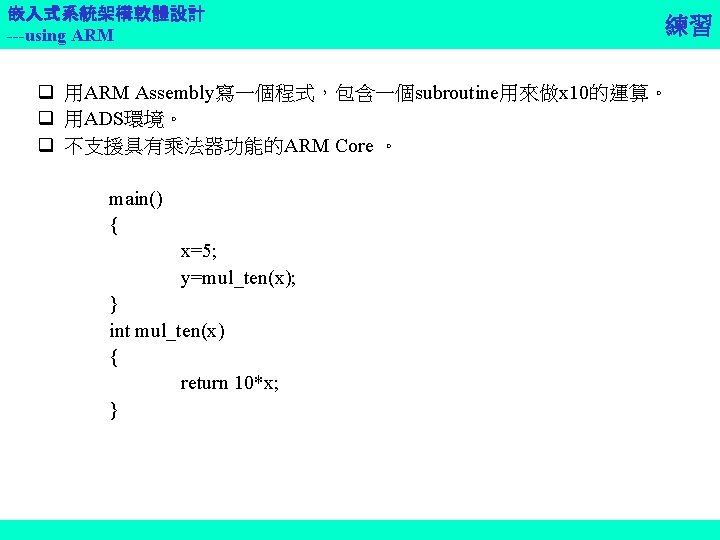
![嵌入式系統架構軟體設計 ---using ARM q Single register load and store LDR r 0, [r 1]](http://slidetodoc.com/presentation_image_h/afab72fd2cf81a40fa642cede9d5af6c/image-54.jpg "嵌入式系統架構軟體設計 ---using ARM q Single register load and store LDR r 0, [r 1]")
嵌入式系統架構軟體設計 ---using ARM q Single register load and store LDR r 0, [r 1] STR r 0, [r 1] q Base plus offset addressing Pre-indexing LDR r 0, [r 1, #4] Auto indexing LDR r 0, [r 1, #4]! Post-indexed LDR r 0, [r 1], #4 PC-relative LDR STRB … UART_ADD & Load and Store Examples ; r 0 : = mem 32[r 1] ; mem 32[r 1] : = r 0 ; r 0 : = mem 32[r 1+4], r 1=r 1+4 ; r 0 : = mem 32[r 1], r 1=r 1+4 r 1, UART_ADD r 0, [r 1] ; UART address into r 1 ; store data to UART &10000000 ; address literal

嵌入式系統架構軟體設計 ---using ARM Assemble Format: LDR|STR{<cond>}H |SH|SB • An unsigned value is zeroextended to 32 bits when loaded; • A singed value is extended to 32 bits by replicating the most significant bit of the data. Half-word and Signed Byte Data Transfer Instruction Binary Encoding Rd; [Rn, <offset>]{!} ; Pre-indexed form Rd; [Rn], <offset> ; Post-indexed form

嵌入式系統架構軟體設計 ---using ARM ADR ADR LOOP LDRSH STR CMP BLT r 1, ARRAY 1 r 2, ARRAY 2 r 3, ENDARR 1 r 0, [r 1], #2 r 0, [r 2], #4 r 1, r 3 LOOP Half-word Load/Store Example ; half-word array start ; ARRAY 1 end +2 ; get signed half-word ; save word ; check for end of array ; if not finished, loop

嵌入式系統架構軟體設計 ---using ARM Multiple Register Data Transfer Instruction Binary Encoding Assembly Format: LDM|STM{<cond>}<add mode> Rn{!}, <registers> <add mode> IA: Increment after. IB: Increment before. DA: Decrement after. DB: Decrement before. In a non-user mode, CPSP may be restored by: LDM|{<cond>}<add mode> Rn{!}, <registers, PC>^ Full or empty: The stack pointer can either point to the last item in the stack (a full stack), or the next free space on the stack (an empty stack).

嵌入式系統架構軟體設計 ---using ARM Example Addressing Mode for LDM/STM
 {")
嵌入式系統架構軟體設計 ---using ARM ISR Example q e. g. Interrupt handler __irq void IRQHandler(void) { volatile unsigned int *base=(unsigned int *) 0 x 80000000; If (*base==1) C_int_handler_1( ); IRQHandler PROC *(base+1)=0; STMFD spl, {r 0 -r 4, r 12, lr} } MOV LDR SUB CMP BLEQ MOV STR ADD LDMFD SUBS r 4, #0 x 80000000 r 0, [r 4, #0] sp, #4 r 0, #1 C_int_handler r 0, #0 r 0, [r 4, #4] sp, #4 spl, {r 0 -r 4, r 12, lr} pc, lr, #4
![嵌入式系統架構軟體設計 ---using ARM Assembly Format: SWP{<cond>}{B} Rd, Rm, [Rn] Swap Memory and Register Instruction](http://slidetodoc.com/presentation_image_h/afab72fd2cf81a40fa642cede9d5af6c/image-61.jpg "嵌入式系統架構軟體設計 ---using ARM Assembly Format: SWP{<cond>}{B} Rd, Rm, [Rn] Swap Memory and Register Instruction")
嵌入式系統架構軟體設計 ---using ARM Assembly Format: SWP{<cond>}{B} Rd, Rm, [Rn] Swap Memory and Register Instruction Binary Encoding
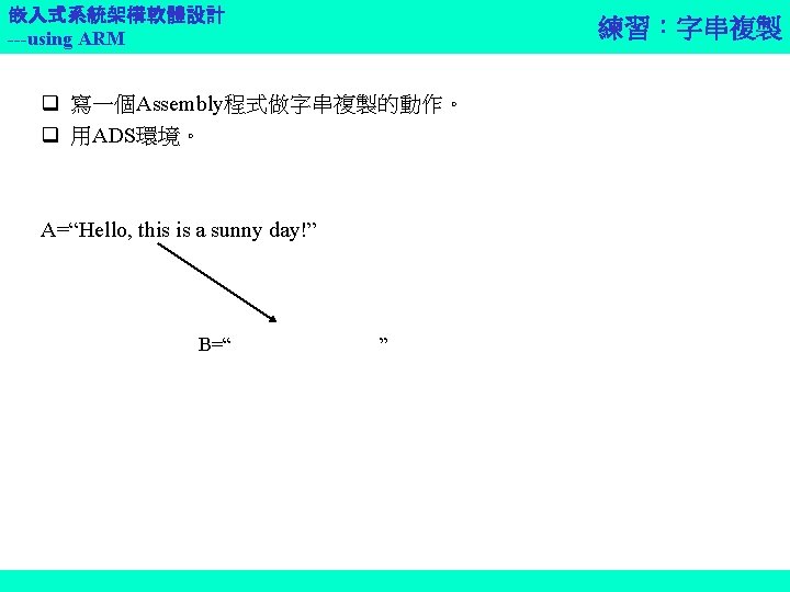
![嵌入式系統架構軟體設計 ---using ARM SWP Example ADR r 0, SEMAPHORE SWPB r 1, [r 0]](http://slidetodoc.com/presentation_image_h/afab72fd2cf81a40fa642cede9d5af6c/image-62.jpg "嵌入式系統架構軟體設計 ---using ARM SWP Example ADR r 0, SEMAPHORE SWPB r 1, [r 0]")
嵌入式系統架構軟體設計 ---using ARM SWP Example ADR r 0, SEMAPHORE SWPB r 1, [r 0] r 0 ; exchange byte r 1 0 r?

嵌入式系統架構軟體設計 ---using ARM Status Register to General Register Transfer Instruction Binary Encoding Assembly Format: MRS{<cond>} Rd, CPSR|SPSR E. g. MRS r 0, CPSR MRS r 3, CPSR ; move the CPSR to r 0 ; move the SPSR to r 3 Note: The SPSR form should not be used in user or system mode.

嵌入式系統架構軟體設計 ---using ARM Transfer to Status Register Instruction Binary Encoding Assembly Format: MRS{<cond>} CPSR_f|SPSR_f, #<32 -bit immediate> MRS{<cond>} CPSR_<field>|SPSR_<field>, Rm <field> C - the control field – PSR[7: 0] X – the extension field – PSR[15: 8] S – the status field – PSR[23: 16] F – the flags field – PSR[31: 24]

嵌入式系統架構軟體設計 ---using ARM q Set N, C, V, Z flags: MSR CPSR_f, #&f 0000000 q Set C flag, preserving N, Z, and V MRS r 0, CPSR ORR r 0, #&20000000 MSR CPSR_f, r 0 MSR Example ; set all the flags ; move the CPSR to r 0 ; set bit 29 of r 0 : move back to CRSR

嵌入式系統架構軟體設計 ---using ARM 練習:切換ARM操作模式 q 寫一段程式,將ARM由Supervisory mode切換到IRQ mode。 q 用ADS環境。 31 30 29 28 27 N Z C V Q 24 J undefined 7 6 5 4 0 I F T mode q Mode bits Specify the processor mode 10000 User 10001 FIQ 10010 IRQ 10011 SVC 10111 Abort 11011 Undef 11111 System

嵌入式系統架構軟體設計 ---using ARM Coprocessor Instructions q There are 3 types: Coprocessor data operations • CDP: initiate a coprocessor data processing operation Coprocessor Register transfers • MRC: Move to ARM register from coprocessor register • MCR: Move to coprocessor register from ARM register Coprocessor Memory transfer • LDC: load coprocessor register from memory • STC: store from coprocessor register to memory

嵌入式系統架構軟體設計 ---using ARM Exception-generating & Semaphore Instructions q SWI Used to cause a Software Interrupt exception to occur SWI {<cond>} <immed_24> SWI 0 x 123456 q BKPT Used from software breakpoints in ARM architecture 5 or above. Cause a Prefetch Abort exception to occur. BKPT <immediate>

嵌入式系統架構軟體設計 ---using ARM Summary of ARM Architectures Core Architecture ARM 1 v 1 ARM 2 v 2 ARM 2 as, ARM 3 v 2 a ARM 6, ARM 600, ARM 610 v 3 ARM 7, ARM 700, ARM 710 v 3 ARM 7 TDMI, ARM 710 T, ARM 720 T, ARM 740 T v 4 T Strong. ARM, ARM 810 v 4 ARM 9 TDMI, ARM 920 T, ARM 940 T v 4 T ARM 9 ES, XScale Microarchitecture v 5 TE ARM 10 TDMI, ARM 1020 E v 5 TE 926 EJ-S/1026 EJ-S v 5 TEJ

嵌入式系統架構軟體設計 ---using ARM Reference q S. Furber, ARM system-on-chip Architecture, 2 nd ed. Addison-Wesley q Seal. ARM architecture reference manual, 2 nd ed. Addison-Wesley q ARM Development Suite User Guide

嵌入式系統架構軟體設計 ---using ARM 嵌入式系統架構軟體設計 --- using ARM Module #3 -5: Important ARM ASM Programming Skills

嵌入式系統架構軟體設計 ---using ARM q Direct loading with MOV and MVN q Loading with LDR Rd, =const Load Constant into Register

嵌入式系統架構軟體設計 ---using ARM Direct Load Constant into Register q Mov{cond}{S}, Operand 2 Load immediate constant to register E. g. • MOV R 1, 0 x 18 ; R 1=0 x 18 Can load any 8 -bit constant, giving a range of 0 x 00 to 0 x. FF q MVN: load the bitwise complement of these values. The numerical values are –(n+1). 224 Compiler ERROR MSG: Immediate n out of range for this operation.

嵌入式系統架構軟體設計 ---using ARM Loading with LDR Rd, =const q The LDR Rd, =const pseudo-instruction can construct any 32 -bit numeric constant in a single instruction q The LDR pseudo-instruction generates the most efficient code for a specific constant: If the constant can be constructed with a MOV or MVN instruction, the assembler generates the appropriate instruction. If the constant cannot be constructed with a MOV or MVN instruction, the assembler: • Places the value in a literal pool. • Generates an LDR instruction with a program-relative address that reads the constant from the literal pool. q e. g. : LDR Rn, [pc, #offset to literal pool] ; load register n with one word from the address [pc+offset] Literal Pool: A portion of memory embedded in the code to hold constant values.

嵌入式系統架構軟體設計 ---using ARM LDR & Literal Pool Example ; ; c: ARMADSv 1_2Examplesasmloadcon. s AREA Loadcon, CODE, READONLY ENTRY START BL func 1 BL func 2 stop MOV r 0, #0 x 18 ; =>MOV R 0, #42 LDR r 1, =0 x 20026 SWI 0 x 123456 func 1 LDR r 0, =42 ; =>MOV R 0, #42 LDR r 1, =0 x 5555 ; =>LDR R 1, [PC, #offset to Literal Pool l] LDR r 2, =0 x. FFFF ; =>MVN R 2, #0 MOV pc, lr LTORG Litetal Pool l constains Litetal 0 x 5555 func 2 LDR r 3, =0 x 5555 ; =>LDR R 3, [PC, #offset to Literal Pool l] LDR r 4, =0 x 6666 ; If this is uncommented it is out of reach ; fails, because Literal Pool 2 MOV pc, lr Large. Table SPACE 4200 ; Starting at the current location ; clears a 4200 bytes area of memory ; to zero, reserves a zeroed block of memory ; Literal Pool 2 is empty END

嵌入式系統架構軟體設計 ---using ARM Loading Addresses into Registers q Direct loading with ADR and ADRL q Loading addresses with LDR Rd, =label.

嵌入式系統架構軟體設計 ---using ARM Direct Loading with ADR q The assembler converts an ADR Rn, label pseudo-instruction by generating: A single ADD or SUB instruction that loads the address, if it is in range An error message if the address cannot be reached in a single instruction. The offset range is 255 bytes for an offset to a non word-aligned address, and 1020 bytes (255 words) for an offset to a word-aligned address. E. g. • ADR r 2, Label+1000 • ADR r 2, Label +211

嵌入式系統架構軟體設計 ---using ARM Direct Loading with ADRL q The assembler converts an ADR Rn, label pseudo-instruction by generating: Two data-processing instruction that load the address, if it is in range An error message if the address cannot be constructed in two instructions The range of an ADRL pseudo-instruction is 64 KB for a non wordaligned address and 256 KB for a word-aligned address. E. g. • ADRL r 2, Label +4300

嵌入式系統架構軟體設計 ---using ARM ADR and ADRL Example ; c: ARMADSv 1_2Examplesasmadrlabel. s AREA adrlabel, CODE, READONLY ENTRY START BL func stop MOV r 0, #0 x 18 ; angel_SWIreason_Report. Exception LDR r 1, =0 x 20026 ; ADP_Stopped_Application. Exit SWI 0 x 123456 ; ARM semihosting SWI LTORG ; Create a literal pool Func ADR r 0, Start ; =>SUB r 0, PC, #offset to Start ADR r 1, Data. Area ; =>ADD r 1, PC, #offset to Data. Area ; ADR r 2, Data. Area+4300 ; =>This would fail because the offset ; cannot be expressed by operand 2 of an ADD ADRL r 2, Data. Area+4300 ; =>ADD r 2, #offset 1 ; ADD r 2, #offset 2 MOV pc, lr ; Return Data. Area SPACE 8000 END ; Starting at the current location. ; clears a 8000 byte area of memory to zero

嵌入式系統架構軟體設計 ---using ARM Loading Addresses with LDR Rd, =label q Load any 32 -bit constant into a register q The assembler converts an LDR r 0, =label pseudo-instruction by: Placing the address of label in a literal pool (a portion of memory embedded in the code to hold constant values). Generating a program-relative LDR instruction that reads the address from the literal pool, for example: LDR rn [pc, #offset to literal pool ] ; load register n with one word from the address [ pc + offset ]

嵌入式系統架構軟體設計 ---using ARM Example for LDR Rd, =label ; c: ARMADSv 1_2examplesasmldriabel. s AREA LDRlabel, CODE, READONLY ENTRY START BL func 1 BL func 2 stop MOV r 0, #0 x 18 LDR r 1, =0 x 20026 SWI 0 x 123456 func 1 LDR r 0, =start ; =>LDR R 0, [PC, #offset into Literal Pool 1] LDR r 1, =Darea+12 ; =>LDR R 1, [PC, #offset into Literal Pool 1] LDR r 2, =Darea+6000 ; =>LDR R 2, [PC, #offset into Literal Pool 1] MOV pc, lr LTORG ; Litetal Pool l func 2 LDR r 3, =Darea+6000 ; =>LDR R 3, [PC, #offset into Literal Pool 1](sharing with previous literal) ; LDR r 4, =Darea+6004 ; If uncommented produces an error as Literal Pool 2 is out of range MOV pc, lr Darea SPACE 8000 ; Literal Pool 2 is out of range of the LDR instructions above END

嵌入式系統架構軟體設計 ---using ARM ; c: ARMADSv 1_2examplesasmjump. s AREA Jump, CODE, READONLY CODE 32 Num EQU 2 ENTRY START MOV r 0, #0 MOV r 0, #3 MOV r 0, #2 BL arithfunc stop MOV r 0, #0 x 18 LDR r 1, =0 x 20026 SWI 0 x 123456 arithfunc CMP r 0, #num MOVHS pc, lr ADR r 3, Jump. Table LDR pc, [R 3, R 0, LSL#2] LTORG Jump. Table DCD Do. Add DCD Do. Sub Do. Add ADD r 0, r 1, r 2 MOV pc, lr Do. Sub SUB r 0, r 1, r 2 MOV pc, lr END Exercise: Implement a Jump Table ; Number of entries in jump table ; Set up the three parameters ; Call the function ; Label the function ; Treat function code as unsigned integer ; if code is >=num then simply return ; load address of jump table ; Jump to the appropriate routine ; Operation 0 ; Return ; Operation 1 ; Return ; Mark the end of the file Trace this program! And make a flow chart.

嵌入式系統架構軟體設計 ---using ARM ; c: ARMADSv 1_2examplesasmstrcopy. s AREA Str. Copy, CODE, READONLY ENTRY Start LDR r 0, =srcstr LDR r 0, =dststr BL strcopy Stop MOV r 0, #0 x 18 LDR r 1, =0 x 20026 SWI 0 x 123456 strcopy LDRB r 2, [r 1], #1 STRB r 2, [r 0], #1 CMP r 2, #0 BNE strcopy MOV pc, lr AREA srcstr dststr END Exercise: String Copy Trace this program! And make a flow chart. ; Point to first string ; Point to second string ; Call subroutine to do copy ; Load byte and update address ; Store byte and update address ; Check for zero terminator ; Keep going if not Strings, DATA, READWRITE DCB "First string-source", 0 DCB "Second string-destination", 0

嵌入式系統架構軟體設計 ---using ARM Load and Store Multiple Register Instructions q An efficient way of moving the contents of several registers to and from memory q Used for block copy and for stack operations at subroutine entry and exit q The advantages include: (Compare to single L/S) Smaller code size Single instructions fetch overhead On uncached ARM processors, the first word of data transferred by a load or store multiple is always a nonsequential memory cycle, but all subsequent words transferred can be sequential memory cycles.
")
嵌入式系統架構軟體設計 ---using ARM LDM and STM Instructions q The load ( or store ) multiple instruction loads (stores) any subset of the 16 general-purposes registers from (to) memory, using a single instruction. q Syntax: LDM {cond} address-mode Rn{1}, reg-list{^} !: Specifies base register write back. If this is specified, the address in the base register is updated after the transfer. ^: Specifies that the CPSR is restored from the SPSR. It must be used only from a privileged mode (i. e. other than user mode). q E. g. LDMIA STMIA r 0!, {r 2 -r 9} r 1, {r 0 -r 10}.

嵌入式系統架構軟體設計 ---using ARM q q Addressing Mode for LDM/STM IA: Increment after IB: Increment before DA: Decrement after DB: Decrement before q Full of empty: The stack pointer can either point to the last item in the stack (a full stack), or the next free space on the stack (an empty stack). q Note: The ARM-Thumb Procedure Call Standard (ATPCS), and ARM and Thumb C and C++ compiles always use a full descending stack.

嵌入式系統架構軟體設計 ---using ARM Example Addressing mode for LDM/STM

嵌入式系統架構軟體設計 ---using ARM Stacking Registers for Nested Subroutines Subroutine STMFD sp!, {r 5 -r 7, r} …… ; code …. BL ; Push work registers and lr Note: Your codes use r 5, r 6, r 7, lr xxxx_xxxx …… ; code …… LDMFD sp!, {f 5 -f 7, pc} ; Pop work registers and pc

嵌入式系統架構軟體設計 ---using ARM $Label Using Macro MACRO Test. And. Branch $dest, $reg, $cc CMP $reg, #0 B$cc $dest MEND This macro can be invoked as follows: test Test. And. Branch Non Zero, r 0, NE … … Non. Zero After substitution this becomes: test CMP r 0, #0 BNE Non. Zero … … Non. Zero

嵌入式系統架構軟體設計 ---using ARM Module #4 -1: ARM-Thumb Interworking

嵌入式系統架構軟體設計 ---using ARM q To ensure that separately compiled or assembled subroutines can work together. q Register roles and names q The stack A full, descending stack Eight-byte alignment at all external interfaces. ARM-Thumb Procedure Call Standard (ATPCS)

嵌入式系統架構軟體設計 ---using ARM Parameter Passing q Nonvariadic: A routine with a fixed number of arguments is. The first integer arguments are allocated to r 0 -r 3 in order. Remaining parameters are allocated to the stack in order. q Variadic routine: A routine with a variable number of arguments. a 1 -a 4, a 1 first. The stack, lowest address first. #include <stdarg. h> int Show. Var(char *sz. Types, . . . ) { va_list vl; va_start (vl, sz. Types); . . . } void main() { Show. Var("fcsi", 32, 4 f, 'a', "Test string", 4); }

嵌入式系統架構軟體設計 ---using ARM When to Use Interworking q Code density Thumb state has better code density q Speed consideration Running in ARM state has better efficiency than Thumb state. q Functionality Thumb instructions are less flexible than their ARM equivalents. Some operations are not possible in thumb state. • e. g. enable/disable interrupt & A state change. q Exception handing The processor automatically enters ARM state when a processor exception occurs. This means that the first part of an exception handler must be coded with ARM instructions, even if it re-enters Thumb state to carry out the main processing of the exception. q Standalone Thumb programs q A thumb-capable ARM processor always starts in ARM state.

嵌入式系統架構軟體設計 ---using ARM Non-interworking Function Call q Implementing a function call usually requires two steps: Store the return address in the link register (LR) Branch to the address of the required function void mouse() { … monkey(); … } void monkey() { … return(); } ; mouse() … BL monkey … ; monkey() … MOV pc, lr

嵌入式系統架構軟體設計 ---using ARM/Thumb Interworking Function Call q Use BX or BLX q BX does not store return address in LR automatically. -> return from function by BX LR to original state. q v 5 T supports BLX

嵌入式系統架構軟體設計 ---using ARM BLX Example q A call to Thumb subroutine: TSUB CODE 32 …. . BLX TSUB …. CODE 16 …. BX r 14 ; ARM code follows ; call thumb routine ; start of Thumb code ; Thumb subroutine ; return

嵌入式系統架構軟體設計 ---using ARM AREA ENTRY ARM/Thumb Interworking Example Add. Reg. CODE, READONLY ; Name this block of code. ; Mark first instruction to call. main ADR r 0, Thumb. Prog + 1 BXr 0 ; Generate branch target address ; and set bit 0, hence arrive ; at target in Thumb state. ; Branch exchange to Thumb. Prog CODE 16 ; Subsequent instructions are Thumb code MOV r 2, #2 MOV r 3, #3 ADD r 2, r 3 ADR r 0, ARMProg BX r 0 ; Load r 2 with value 2 ; Load r 2 with value 3 ; r 2=r 2+r 3 CODE 32 ; Subsequent instructions are ARM code. Thumb. Prog ARMProg MOV r 4, #4 MOV r 5, #5 ADD r 4, r 5 Stop MOV r 0, #0 x 18 LDR r 1, =0 x 20026 SWI 0 x 123456 END ; angel_SWIreason_Report. Exception ; ADP_Stopped_Application. Exit ; ARM semihosting SWI ; Mark end of this file

嵌入式系統架構軟體設計 ---using ARM 練習:ARM/Thumb Interworking #1 q Trace code: ADSv 1_2exampleasmthumbsub. mcp Monitor CPSR with PC

嵌入式系統架構軟體設計 ---using ARM C Functions&Interworking q Compiler C to run in Thumb&support interworking tcc -c-g-O 1 -apcs/interwork thumbmain. c q Compiler C to run in ARM state & support intherworking armcc -c-g-O 1 -apcs/interwork armsub. c q Link armlink thumbmain. o armsub. o -o thumbtoarm. axf -info veneers ; By armcc –apcs/interwork xxx Void xxx() STMFD SP!, {r 4 -r 11, lr} { … … BL sub func(); … … LDMFD SP!, {r 4 -r 11, lr} BX lr } ; By tcc –apcs/interwork xxx PUSH SP!, {r 4 -r 7, lr} … BL sub … POP SP!, {r 4 -r 7, lr} POP {r 3} BX r 3
 code calling")
嵌入式系統架構軟體設計 ---using ARM 練習:ARM/Thumb Interworking #2 ADSv 1_2examplesinterwork*. c 1. ARM (main) code calling a Thumb subroutine armcc -c-g-O 1 - apcs/interwork armmain. c tcc -c -g-O 1 -apcs/interwork thumbsub. c armlink armmain. o thumbsub. o -o armtothumb. axf -info veneers 2. Thumb (main) code calling an Arm subroutine tcc -c-g-O 1 -apcs/interwork thumbmain. c armcc -c -g-O 1 –apcs/interwork armsub. c armlink thumbmain. o armsub. o -o thumbtoarm. axf -info veneers q Run the code by AXD

嵌入式系統架構軟體設計 ---using ARM q Inline Assembler q C calls ASM function q ASM call C function Mixing C & Assembler

嵌入式系統架構軟體設計 ---using ARM Inline Assembler q The ARM C compiler support inline assembly language with the ___asm specifier. q The ARM C++ compilers support the asm syntax proposed in the ANSI C++ Standard, with the restriction that the string literal must be a single string. e. g: asm(“instruction[; instruction]”); q ARM C++ supports the C compiler ___asm sytax. ___asm { instruction [; instruction] … [instruction] }

嵌入式系統架構軟體設計 ---using ARM Restriction of Inline Assembler q Not support LDR Rn, =express Label expression ADR, ADRL & can’t be used to express hex. (use 0 x prefix instead) BX, BLX q Can’t write to PC
 { const char *a=“Hello world!”; char")
嵌入式系統架構軟體設計 ---using ARM #include <stdio. h> int main(void) { const char *a=“Hello world!”; char b[20]; __asm { MOV R 0, a MOV R 1, b BL my_strcpy, {R 0, R 1} } printf(“Original string: %sn”, a); printf(“Copied string: %sn”, b); return 0; } String Copy Example Void my_strcpy(char *src, const char *dst ) { int ch; ___asm { loop: #ifndef___thumb // Arm version LDRB ch, [src], #1 STRB ch, [dst], #1 #else //Thumb version LDRB ch, [src] ADD src, #1 STRB ch, [dst] ADD dst, #1 #endif CMP ch, #0 BNE loop } }

嵌入式系統架構軟體設計 ---using ARM Some Issues to Use Inline Assembler q Use r 0 -r 3, ip, lr and CPSR with caution. E. g. Int funct(int x) { …. __asm { add r 0, #1 } add x, x, #1 //we can’t assert x is in r 0 //correct usage q Don’t save &restore physical registers. E. g. int funct(int x) { …. __asm { stmfd add eor ldmfd } } sp! {r 0} r 0, x, 1 x, r 0, x sp!, {r 0} //save r 0 //restore r 0
 {return g(i, 2*i, 3*i, 4*i, 5*i); }")
嵌入式系統架構軟體設計 ---using ARM ; int f(int i) {return g(i, 2*i, 3*i, 4*i, 5*i); } ASM calls C example int g(int a, int b, int d, int e) { return a+b+c+d+e; } EXPORT f AREA f, CODE, READONLY IMPORT g ; i is in r 0 str LR, [SP, #-4]! ; preserve lr ADD r 1, r 0 ; computer 2*i (2 nd param) ADD r 2, r 1, r 0 ; computer 3*i (3 nd param) ADD r 3, r 1, r 2 ; computer 5*i STR r 3, [sp, #4]! ; 5 th param on stack ADD r 3, r 1 ; computer 4*i (4 nd param) BL g ; branch to C function ADD sp, #4 ; remove 5 th param LDR pc, [sp], #4 ; return END

嵌入式系統架構軟體設計 ---using ARM Access C Global Variables q Use “IMPORT” q Use “LDR/STR” q E. g. AREA global_variable, CODE, READONLY EXPORT asmsub IMPORT glob_var asmsub ldr add str mov END r 1, =glob_var r 0, [r 1] r 0, #10 r 0, [r 1] pc, lr ; read address of glob_var ; into r 1 from literal pool

嵌入式系統架構軟體設計 ---using ARM C call ASM Example install_directoryexampleasm as strtest. c and scopy. s #include <stdio. h> extern void strcopy(char*d, const char *s); int main() { const char *srcstr = “First string -source”; char dststr[] = “Second string - destination”; / *dststr is an array since we’re going to change it*/ printf(“Before copying: n”); printf(“%sn”, srcstr, dststr); strcopy(dststr, srcstr); printf(“After copying: n”); printf(“ %sn”, srcstr, dststr); return(0); } AREA SCopy, CODE, REAONLY EXPORT strcopy ; r 0 points to destination string. ; r 1 points to source string. LDRB r 2, [r 1], #1 ; Load byte and update address. STRB r 2, [r 0], #1 ; Store byte and update address. CMP r 2, #0 ; Check for zero terminator. BNE strcopy ; Keep going if not. MOV pc, lr ; Return. END

嵌入式系統架構軟體設計 ---using ARM 練習:Inlie IRQ Controller q 分別寫一個disable interrupt 和enable interrupt 的inline assembler subroutine。 __inline void enable_IRQ(void) { …. . } __inline void disable_IRQ(void) { …. . } q 在c 的main function 去呼叫執行

嵌入式系統架構軟體設計 ---using ARM Module #4 -2: ARM Exception Handler

嵌入式系統架構軟體設計 ---using ARM Exception Type & Vector Address

嵌入式系統架構軟體設計 ---using ARM Exception Handling by ARM Core q When an exception occurs, the banked versions of R 14 and the SPSR for the exception mode are used to save state as follows: 1. R 14_<exception_mode> = return link 2. SPSR_<exception_mode> = CPSR 3. CPSR[4: 0] = exception mode number 4. CPSR[5] = 0 /*Execute in ARM state*/ 5. if <exception_mode> = = Reset or FIQ then? ? 6. CPSR[6] = 1 /*Disable fast interrupt else CPSR[6] is unchanged*/ 7. CPSR[7] = 1 /* Disable normal interrupts*/ Priority Exception 8. PC = exception vector address Highest 1 q Summary: Copy PC into r 14_mode, save CPSR into SPSR Change to appropriate exception mode PC is force to 0 x 0 -0 x 1 c Lowest Reset 2 Data Abort 3 FIQ 4 IRQ 5 Prefetch Abort 6 Undefined instruction SWI

嵌入式系統架構軟體設計 ---using ARM Reset Exception 1. R 14_svc = UNPREDICTABLE value 2. SPSR_svc = UNPREDICTABLE value 3. CPSR[4: 0] = 0 b 10011 /*enter supervisory mode*/ 4. CPSR[5] = 0 /*Execute in ARM state*/ 5. CPSR[6] = 1 /*Disable fast interrupts*/ 6. CPSR[7] = 1 /*Disable normal interrupts*/ 7. If high vectors configured then PC = 0 x. FFFF 0000 else PC = 0 x 0000

嵌入式系統架構軟體設計 ---using ARM Undefined Instruction Exception q While to execute an co-processor instruction, ARM can’t get response from co-processor. q Attempt to execute an instruction that is UNDEFINED. q Can be used for software emulation of a coprocessor in a system that does not have physical coprocessor. q Action performed: 1. R 14_und = address of next instruction after the undefined instruction 2. SPSR_und = CPSR 3. CPSR[4: 0] = 0 b 11011 /*enter Undefined mode*/ 4. CPSR[5] = 0 /*Execute in ARM state*/ 5. CPSR[6] /*unchanged*/ 6. CPSR[7] = 1 /*Disable normal interrupts*/ 7. If high vectors configured then PC = 0 x. FFFF 0004 else PC = 0 x 00000004
 enters supervisor mode. q")
嵌入式系統架構軟體設計 ---using ARM Software Interrupt q Software Interrupt Instruction (SWI) enters supervisor mode. q Action performed: 1. R 14_svc = address of next instruction after the undefined instruction 2. SPSR_svc = CPSR 3. CPSR[4: 0] = 0 b 10011 /*enter supervisor mode*/ 4. CPSR[5] = 0 /*Execute in ARM state*/ 5. CPSR[6] /*unchanged*/ 6. CPSR[7] = 1 /*Disable normal interrupts*/ 7. If high vectors configured then PC = 0 x. FFFF 0008 else PC = 0 x 00000008

Return from Undefined Instruction &Software Interrupt Exceptions 嵌入式系統架構軟體設計 ---using ARM q Simple MOVS q In exception handler STMFD …. LDMFD pc, lr sp!, {reglist, lr} sp!, {reglist, pc}^ ^: Auto restore CPSR from SPSR.

嵌入式系統架構軟體設計 ---using ARM Prefetch Abort Exception q If processor attempts to fetch an instruction from an illegal address, the instruction is marked as invalid. (in pipeline) q When reach the invalid instruction, prefetch abort exception is generated. 1. R 14_abt = address of aborted instruction +4 2. SPSR_abt = CPSR 3. CPSR[4: 0] = 0 b 10111 /*enter Abort mode*/ 4. CPSR[5] = 0 /*Execute in ARM state*/ 5. CPSR[6] /*unchanged*/ 6. CPSR[7] = 1 /*Disable normal interrupts*/ 7. If high vectors configured then PC = 0 x. FFFF 000 C else PC = 0 x 0000000 C

嵌入式系統架構軟體設計 ---using ARM q Simple SUBS q Exception handler SUBS STMFD …. . LDMFD Return from Prefetch Abort Exception pc, lr, #4 sp!, {reglist, lr} sp!, {reglist, pc}^

嵌入式系統架構軟體設計 ---using ARM q Signaled by the memory system. q Action performed: 1. R 14_abt = address of aborted instruction +8 2. SPSR_abt = CPSR 3. CPSR[4: 0] = 0 b 10111 /*enter Abort mode*/ 4. CPSR[5] = 0 /*Execute in ARM state*/ 5. CPSR[6] /*unchanged*/ 6. CPSR[7] = 1 /*Disable normal interrupts*/ 7. If high vectors configured then PC = 0 x. FFFF 0010 else PC = 0 x 00000010 Data Abort

嵌入式系統架構軟體設計 ---using ARM q Simple SUBS q Exception handler SUBS STMFD …. LDMFD Return from Data Abort Exception pc, lr, #8 sp!, {reglist, lr} sp!, {reglist, pc}^

嵌入式系統架構軟體設計 ---using ARM FIQ Exception Handling by ARM When an FIQ is detected, the following actions are performed: R 14_fiq = address of next instruction to be executed +4 SPSR_fiq = CPSR[4: 0] = 0 b 10001 /*enter FIQ mode*/ CPSR[5] = 0 /*Execute in ARM state*/ CPSR[6] = 1 /*Disable fast interrupts*/ CPSR[7] = 1 /*Disable normal interrupts*/ If high vectors configured then PC = 0 x. FFFF 001 C else PC = 0 x 0000001 C To return after servicing the interrupt, use: SUBS PC, R 14, #4

嵌入式系統架構軟體設計 ---using ARM FIQ Exception Handler by Programmer q Your FIQ handler SUBS STMFD …. …. LDMFD lr, #4 sp!, {r 0 -r 4, lr} sp!, {r 0 -r 4, pc}^

嵌入式系統架構軟體設計 ---using ARM IRQ Exception q Action performed: 1. R 14_irq = address of next instruction to be executed +4 2. SPSR_abt = CPSR 3. CPSR[4: 0] = 0 b 10010 /*enter IRQ mode*/ 4. CPSR[5] = 0 /*Execute in ARM state*/ 5. CPSR[6] /*unchanged*/ 6. CPSR[7] = 1 /*Disable normal interrupts*/ 7. If high vectors configured then PC = 0 x. FFFF 0018 else PC = 0 x 00000018 Return SUBS pc, lr, #4

嵌入式系統架構軟體設計 ---using ARM Implement a SWI Handler q ADSv 1_2examplesswi* main. c installs the SWI vector in the exception table, then calls SWIs (0, 1, 2 & 3) via__swi(). ahandle. s top-level SWI handler written in assembler. Identify ARM&thumb SWIs then pass to chandle. c for processing. chandle. c second-level SWI handler, called from ahandle. s. SWIs 0, 1, 2 & 3 execute some simple arithmetic. Swi. h contains the definitions of __swi(), __swi(1), __swi(2) &__swi(3).

嵌入式系統架構軟體設計 ---using ARM Calling SWI from An Application q In assembly, set up required register values then issue SWI. MOV r 0, #65 SWI 0 x 0 ; call SWI 0 x 0 with parameter value in r 0 q C/C++, declare the SWI as an __SWI function, and call it. ___swi() void my__swi(int); … my__swi(65); q Provide that: Any arguments are passed in r 0 -r 3 only. Any results are returned in r 0 -r 3 only. • If there are 2 -4 return values, those must be returned by a structure. Directive as __value_in_regs
 int multiply_two(int, int);")
嵌入式系統架構軟體設計 ---using ARM SWI Function Declare&Usage // from exampleSWIswi. h __swi(0) int multiply_two(int, int); __swi(1) int add_two(int, int); __swi(2) int add_multiply_two(int, int); struct four_results { int a; int b; int c; int d; }; __swi(3) __value_in_regs struct four _results many_operations(int, int); // calling example structure four_results res_3; res_3 = many_operations(1, 2, 3, 4); add_two(1, 2);

嵌入式系統架構軟體設計 ---using ARM Parameters Passing q We can pass values in and out of a SWI handler written in C, provided that the top-level handler passes the stack pointer into the C function as the second parameter. MOV r 1, sp BL C_SWI_Handler Parameter 0 = reg[0] Parameter 1 = reg[1] Parameter 2 = reg[2] Parameter 3 = reg[3] q Write back reg[0] = updated_value_0 reg[1] = updated_value_1 reg[2] = updated_value_2 reg[3] = updated_value_3

嵌入式系統架構軟體設計 ---using ARM Identify SWI q When a SWI handler is entered, it must establish which SWI is being called. Load the SWI instruction that cause the exception. • LDR r 0, [lr, #-4] Extract the SWI number by clearing the 31 -24 bits. • BIC r 0, #0 x. FF 000000

嵌入式系統架構軟體設計 ---using ARM Using SWI in Supervisory Mode q Call a SWI in supervisory mode LR_SVC and SPSR_SVC are corrupted. q Therefore, we must store LR_SVC and SPSR_SVC when a SWI is called. MRS STMFD …. LDMFD MSR r 0, spsr sp!, {r 0} ; Get spsr ; Store spsr onto stack sp!, {r 0} spsr_cf, r 0 ; get spsr from stack ; restore spsr

嵌入式系統架構軟體設計 ---using ARM Identify SWI from Arm/Thumb …. . T_bit EQU 0 x 20 SWI_Handler STMFD MOV MRS STMFD TST LDRNE BICNE LDREQ BICEQ sp!, {r 0 -r 3, r 12, lr} r 1, spsr sp!, {r 0} r 0, #T_bit H r 0, [lr, #-2] r 0, #0 x. FF 00 r 0, [lr, #-4] r 0, #0 x. FF 000000 ; Store registers ; Set pointer to parameters ; Get spsr ; Store spsr onto stack ; Occurred in Thumb state? ; Yes: Load halfword and… ; …extract comment field ; No: Load word and… ; …extract comment field ; r 0 now contains SWI number ; r 1 now contains pointer to stacked registers BL …. C_SWI_Handler ; Call main part of handler
 { switch(swi_num) { case 0: …. break; case")
嵌入式系統架構軟體設計 ---using ARM void C_SWI_Handler(unsigned swi_num) { switch(swi_num) { case 0: …. break; case 1: …. break; case 2: …. break; …. } } Simple C SWI Handler

嵌入式系統架構軟體設計 ---using ARM Install an Exception Handler During Development Work Unsigned Install_Handler(unsigned routine, unsigned *vector) { unsigned vec, old_vec; vec = (routine – (unsigned)vector - 8)>>2; //-8 for prefetching, >> for word offset if (vec & 0 xff 000000) //check is branch offset is out of limit? { printf(“Handler greater than 32 MBytes from vector”); } vec = 0 xea 000000 | vec; // 0 xea 000000 the opcode of branch inst. old_vec = *vector; *vector = vec; return (old_vec); } Usage: unsigned *swi_vec = (unsigned *)0 x 08; extern void SWI_Handler(void); Install_Handler((unsigned) SWI_Handler, swi_vec);
 { volatile unsigned int")
嵌入式系統架構軟體設計 ---using ARM C Interrupt Handlers __irq void IRQHandler (void) { volatile unsigned int *base = (unsigned int *) 0 x 80000000; if(*base = = 1) { c_int_handler(); } *(base+1) = 0; } Note: __irq does not provide reentrant processing

嵌入式系統架構軟體設計 ---using ARM ; with__irq IRQHandler PROC STMFD sp!, {r 0 -r 4, r 12, lr} MOV r 4, #0 x 80000000 LDR r 0, [r 4, #0] SUB sp, #4 CMP r 0, #1 BLEQ C_int_handler MOV r 0, #0 STR r 0, [r 4, #4] ADD sp, #4 LDMFD sp!, {r 0 -r 4, r 12, lr} SUBS pc, lr, #4 ENDP Compiled __irq ; with__irq IRQHandler PROC STMFD sp!, {r 4, lr} MOV r 4, #0 x 80000000 LDR r 0, [r 4, #0] CMP r 0, #1 BLEQ C_int_handler MOV r 0, #0 STR r 0, [r 4, #4] LDMFD sp!, {r 4, pc} ENDP

嵌入式系統架構軟體設計 ---using ARM Reentrant Interrupt Handlers q The steps needed to safely re-enable interrupts in an IRQ handler are: 1. Construct return address and save on the IRQ stack. 2. Save the work registers and spsr__IRQ. 3. Clear the source of the interrupt. 4. Switch to System mode and re-enable interrupts. 5. Save User mode link register and non callee-saved registers. 6. Call the C interrupt handler function. 7. When the C interrupt handler returns, restore User mode registers and disable interrupts. 8. Switch to IRQ mode, disabling interrupts. 9. Restore work registers and spsr__IRQ. 10. Return from the IRQ.

嵌入式系統架構軟體設計 ---using ARM Reentrant Example AREA INTERRUPT, CODE, READONLY IMPORT C_irq_handler IRQ SUB STMFD MRS STMFD lr, #4 sp!, {lr} r 14, SPSR sp!, {r 12, r 14} ; construct the return address ; and push the adjusted lr_IRQ ; copy spsr_IRQ to r 14 ; save work regs and spsr_IRQ ; Add instruction to clear the interrupt here ; then re-enable interrupts. MSR CPSR_c, #0 x 1 F STMFD BL LDMFD MSR sp!, {r 0 -r 3, lr} C_irq_handler sp!, {r 0 -r 3, lr} CPSR_c, #0 x 92 LDMFD MSR LDMFD END sp!, {r 12, r 14} SPSR_cf, r 14 sp!, {pc}^ ; switch to SYS mode, FIQ and IRQ enabled. ; USR mode registers are now current. ; save lr_USR and non-callee saved registers ; branch to C IRQ handler. ; restore registers ; switch to IRQ mode and disable IRQs. FIQ is still enabled. ; restore work regs and spsr_IRQ ; return from IRQ.

嵌入式系統架構軟體設計 ---using ARM Module #4 -3: Build ARM ROM Image

嵌入式系統架構軟體設計 ---using ARM System Startup Load code from address 0 x 0 to execute • SVC mode • Interrupts disable • ARM state System initialization 1. Initialing the execution environment, i. e. exception vectors, stacks, memory system, I/O, etc. 2. Initializing the C library and application (C variables for example). Exception
![嵌入式系統架構軟體設計 ---using ARM q ROM at 0 x 0] Simple Slow to handle exceptions](http://slidetodoc.com/presentation_image_h/afab72fd2cf81a40fa642cede9d5af6c/image-141.jpg "嵌入式系統架構軟體設計 ---using ARM q ROM at 0 x 0] Simple Slow to handle exceptions")
嵌入式系統架構軟體設計 ---using ARM q ROM at 0 x 0] Simple Slow to handle exceptions q RAM at 0 x 0 Complex Fast to handle exceptions System Memory Mapping

嵌入式系統架構軟體設計 ---using ARM 1. Power on to fetch the RESET vector at 0 x 0 (from the aliased copy of ROM). 2. Execute the RESET vector: LDR PC, =0 x 0 C 000004 This causes a jump to the real address of the next ROM instruction 3. Write to the REMAP register and set REMAP = 1. 4. Complete the rest of the initialization code as described in Initializing the system. General Process for Remap

嵌入式系統架構軟體設計 ---using ARM q Reset vector is at 0 x 0 q Initialization process = Reset handler, to Set up exception vectors Initialize the memory system Initialize the stack pointer registers Initialize any critical I/O devices Change processor mode if necessary Change processor state if necessary Initialize System

嵌入式系統架構軟體設計 ---using ARM Set up Exception Vectors q If ROM at address 0 x 0 Vectors consist of a sequence of hard-coded instructions to branch to the handlers. q If ROM at elsewhere Dynamically initialize the vectors by initialization codes. Typically, copy the vector table from ROM to RAM

嵌入式系統架構軟體設計 ---using ARM Example to Set up Exception Vectors ENTRY LDR LDR LDR NOP LDR PC, Reset_Addr PC, Undefined_Addr PC, SWI_Addr PC, Prefetch_Addr PC, Abort_Addr ; Reserved vector PC, IRQ_Addr PC, FIQ_Addr IMPORT Reset_Handler IMPORT IRQ_Handler Reset_Addr Undefined_Addr SWI_Addr Prefetch_Addr Abort_Addr IRQ_Addr FIQ_Addr DCD DCD ; In init. s Reset_Handler Undefined_Handler SWI_Handler Prefetch_Handler Abort_Handler 0; Reserved vector IRQ_Handler FIQ_Handler ; ********* ; Exception Handlers ; ********* Undefined_Handler B Undefined_Handler SWI_Handler B SWI_Handler Prefetch_Handler B Prefetch_Handler Abort_handler B Abort_handler ; IRQ_Handler ; B IRQ_Handler FIQ_Handler B END FIQ_Handler

嵌入式系統架構軟體設計 ---using ARM Initialize The Stack Pointer Registers q Sp_SVC Must always be initialized. q Sp_ IRQ Initialize it if IRQ interrupt used. Initialize before interrupts are enabled. q Sp_FIQ Initialize it if FIQ interrupt used. Initialize before interrupts are enabled. q Sp_ABT Initialize for Data and Prefetch Abort handling q Sp_UND Initialize for Undefined Instruction handling. Initialize sp_ABT and sp_UND for debugging purposes. q Set up the stack pointer sp_USR when changing to User mode to start executing the application.

嵌入式系統架構軟體設計 ---using ARM Mode_USR Mode_ FIQ Mode_IRQ Mode_SVC Mode_ABT Mode_UNDEF Mode_SYS Change Processor Mode & State EQU EQU MSR 0 x 10 0 x 11 0 x 12 0 x 13 0 x 17 0 x 1 B 0 x 1 F; CPSR_c, #Mode_IRQ: OR: I_Bit: OR: F_Bit q Mode bits Specify the processor mode 1, 0000 User 1, 0001 FIQ 1, 0010 IRQ 1, 0011 SVC 1, 0111 Abort 1, 1011 Undef 1, 1111 System

Example to Initialize The Stack Pointer Registers 嵌入式系統架構軟體設計 ---using ARM Mode_IRQ I_Bit F_Bit … … RAM_Limit EQU EUU EQU 0 x 12 0 x 80 0 x 40 EQU 0 x 1000000 SVC_Stack IRQ_Stack. …. …. . . EQU RAM_Limit-1024 ; For 16 MByte SDRAM ; ---Initialize stack pointer registers ; Enter IRQ mode and set up the IRQ stack pointer MSR CPSR_c, #Mode_IRQ: OR: I_Bit: OR: F_Bit LDR SP, =IRQ_Stack

嵌入式系統架構軟體設計 ---using ARM Scatter Loading q Enable us to specify the memory map of an image to armlink. q For more information Refer to: ARM Developer Suite Version 1. 2 Linker and Utilities Guide

嵌入式系統架構軟體設計 ---using ARM ROM_LOAD 0 x 0 { ROM_EXEC 0 x 0 { vectors. o (Vect, +First) * (+RO) } RAM 0 x 28000000 { * (+RW, +ZI) } HEAP +0 UNINIT { heap. o (+ZI) } STACKS 0 x 28080000 UNINIT { stack. o (+ZI) } UART 0 0 x 16000000 UNINIT { uart. o (+ZI) } } Example of Scatter Loading Script All other read only code is placed after vector. o Contain RW and ZI data regions Heap grows from this address Stack grows downward from this address

嵌入式系統架構軟體設計 ---using ARM FLASH 0 x 24000000 0 x 4000000 { init. o (init, +First) * (+RO) } 32 bit. RAM 0 x 0000 { vectors. o (Vect, +First) * (+RW, +ZI) } HEAP +0 UNINIT { heap. o (+ZI) } STACKS 0 x 40000 UNINIT { stack. o (+ZI) } UART 0 0 x 16000000 UNINIT { uart. o (+ZI) } } Example of Scatter Loading Script ROM/RAM Remap

嵌入式系統架構軟體設計 ---using ARM Initialize Application q Initialize nonzero writable data by copying the initializing values (RW from ROM to ROM) to the writable data region q Set all writable data of ZI region to zero. q When the compiler compiles a function called main(), it generates a reference to the symbol__main to force the linker to include the basic C run-time system from the ANSI C library. (The symbol __main is marked as an entry point. )
 In /Retarget. c __value_in_regs struct__initial_stackheap__user_initial_stackheap(unsigned R 0, unsigned SP, unsigned")
嵌入式系統架構軟體設計 ---using ARM __user_initial_stackheap() In /Retarget. c __value_in_regs struct__initial_stackheap__user_initial_stackheap(unsigned R 0, unsigned SP, unsigned R 2, unsigned SL) { struct__initial_stackheap config; config. heap_base = 0 x 00060000; config. stack_base = SP; return config; }

嵌入式系統架構軟體設計 ---using ARM 練習:Build & Trace a ROM Image q Try exampleembeddedembed. mcp q Building an image by ADS q Trace code by AXD

嵌入式系統架構軟體設計 ---using ARM Case Study: Build An Image for Wiscore EVM q Application: 7 -segment LED test Set up Timer 0: Interrupt to flash LED 0 While loop detect switch & change 7 -segment LED number

嵌入式系統架構軟體設計 ---using ARM S 3 C 4510 B Initial Memory Map Figure 4 -2 Initial System Memory Map (After Reset)

嵌入式系統架構軟體設計 ---using ARM S 3 C 4510 B Special Register Base q SYSCFG register determines: Start address of the System Manager’s special registers Start address of internal SRAM. • (The total special register space in the system memory map is fixed at 64 K bytes. ) [15: 6] Internal SRAM base pointer This 10 -bit address becomes the upper address of SRAM. A 25 through A 16, the remaining SRAM address, and A 15 through A 0, are filled with zeros. [25: 16] Special register bank base pointer The resolution of this value is 64 K. Therefore, to place the start address at 1800000 H (24 M), use this formula: Setting value = (1800000 H/64 K)<<16.

嵌入式系統架構軟體設計 ---using ARM NET-Start! EVM Memory Mapping Figure 3 -1 NET-Start! Memory Map Figure 3 -2 Memory Usage

嵌入式系統架構軟體設計 ---using ARM NET-Start! 7 -segment LED&LEDs

嵌入式系統架構軟體設計 ---using ARM GPIO Assignments Figure 2 -8 NET-Start! GPIO assignment Note: The GPIO_IN 1 is used by the bootstrap loader. Selecting the ON position will force the bootstrap loader to run in the diagnostic mode. Otherwise, the embedded Linux will be booted up after system power on.

嵌入式系統架構軟體設計 ---using ARM S 3 C 4510 B Special Registers for I/O Port Figure 12 -1. I/O Port Function Diagram

嵌入式系統架構軟體設計 ---using ARM S 3 C 4510 B IOPMOD

嵌入式系統架構軟體設計 ---using ARM S 3 C 4510 B IOPCON

嵌入式系統架構軟體設計 ---using ARM S 3 C 4510 B IOPDATA Figure 12 -4. I/O Port Data Register (IOPDATA)

嵌入式系統架構軟體設計 ---using ARM #define SYS_BASE #define IOPMOD #define IOPCON #define IOPDATA #define GPIO_LED 0 #define GPIO_LED 1 Example Code to Control LED 0 x 03 ff 0000 ((volatile unsigned*)(SYS_BASE + 0 x 5000)) ((volatile unsigned*)(SYS_BASE + 0 x 5004)) ((volatile unsigned*)(SYS_BASE + 0 x 5008)) 0 x 00010000 0 x 00020000 void Set. LED (int n, int on) { int ctr[] = {GPIO_LED 0, GPIO_LED 1}; if (0 <= n && n< sizeof(ctrl) / sizeof(int)) *IOPDATA = on? (*IOPDATA | ctr[n]) : (*IOPDATA & ~ctrl[n]); }

嵌入式系統架構軟體設計 ---using ARM S 3 C 4510 B Timer

嵌入式系統架構軟體設計 ---using ARM S 3 C 4510 B Special Register TMOD

嵌入式系統架構軟體設計 ---using ARM S 3 C 4510 B Special Register TDATA TIMER DATA REGISTERS The timer data registers, TDATA 0 and TDATA 1, contain a value that specifies the time-out duration for each timer. The formula for calculating the time-out duration is: (Timer data +1) cycles.

嵌入式系統架構軟體設計 ---using ARM S 3 C 4510 B Special Register TCNT TIMER COUNT REGISTERS The timer count registers, TCN 0 and TCNT 1, contain the current timer 0 and 1 count value, respectively, during normal operation.

嵌入式系統架構軟體設計 ---using ARM #define TMOD #define TDATA 0 Example Code to Control Timer *(volatile unsigned*)(SYS_BASE + 0 x 6000) *(volatile unsigned*)(SYS_BASE + 0 x 6004) void Init_Timer() { TDATA 0 = 0 x 17 D 7840 TMOD = 0 x 1; } //MCLK/25 M //enable timer 0 at interval mode

嵌入式系統架構軟體設計 ---using ARM S 3 C 4510 B Interrupt Controller

嵌入式系統架構軟體設計 ---using ARM S 3 C 4510 B Special Register INTMOD

嵌入式系統架構軟體設計 ---using ARM S 3 C 4510 B Special Register INTPND INTERRUPT PENDING REGISTER The interrupt pending register. INTPND contains interrupt pending bits for each interrupt source. This register has to be cleared at the top of an interrupt service routine.

嵌入式系統架構軟體設計 ---using ARM S 3 C 4510 B Special Register INTMSK

嵌入式系統架構軟體設計 ---using ARM S 3 C 4510 B Special Register INTOFFSET q INTERRUPT OFFSET REGISTER The interrupt offset register, INTOFFSET, contains the interrupt offset address of the interrupt, which has the highest priority among the pending interrupts. The content of the interrupt offset address is “bit position value of the interrupt source <<2”. If all interrupt pending bits are “ 0” when you read this register, the return value is “ 0 x 00000054”. 0 x 0000, 0054>>2=21 =Total interrupt

嵌入式系統架構軟體設計 ---using ARM #define INTMOD #define INTPND #define INTMSK #define INTOFFSET Example Code for Timer 0 Interrupt Control *(volatile unsigned*)(SYS_BASE + 0 x 4000) *(volatile unsigned*)(SYS_BASE + 0 x 4004) *(volatile unsigned*)(SYS_BASE + 0 x 4008) *(volatile unsigned*)(SYS_BASE + 0 x 4024) void interrupt_Init. Mask() { INTMSK = 0 x 1 FFBFF; INTPND = 0 x 0; } lrq handler. s STMFD LDR MOV MOV LDR STR LDMFD sp!, {r 1 -r 3} r 3, =INTOFFSET r 2, [r 3] r 2, LSR#2 r 1, #0 x 1 r 1, LSL r 2 r 3, =INTPND r 1, [r 3] sp!, {r 1 -r 3} // enable Timer 0 interrupt Timer 0 IRQ INTOFFSET = 0 b 101000 r 2 = 0 b 101000>>2 = 0 b 1010 = 10

嵌入式系統架構軟體設計 ---using ARM q Commands: HELP-help UNIT – Set access unit DUMP – Memory dump COPY- Memory copy FILL – Fill memory POKE – Poke memory PEEK – Peek memory TX – Send XMODEM file RX – Receive XMODEM file GO – Execute binary INFO – Print system information SWITCH – Switch mode q Load image: Select SW 2 to OFF position Press RESET button Terminal set: bound rate 19200, 8 N 1 RUN>rx 0 x 10000 RUN>copy 0 x 10000 0 x 20000 0 x 1810000 RUN>go 0 x 1810000 Use Net-Start! Bootloader

嵌入式系統架構軟體設計 ---using ARM q q ARM Developer Suite Version 1. 2 Developer Guide ARM Developer Suite Version 1. 2 Linker and Utilities Guide Wiscore Net! Start user Guide SAMSUNG S 3 C 4510 B User Manual Reference
- Slides: 179