CISC vs RISC RISC Design Instructions ARM design


 started as a new, powerful, CPU")
: ADD Rd, Rn, Operand")
 •")


 • Simple instructions (like ADD) Complete at a rate")
 • More complex instructions: STR : 2 effective clock")
")


: Program Counter. Any instruction with PC")


 When the processor is executing in ARM state: All instructions")

 • When the processor is executing in ARM state: –")


- Slides: 47
CISC vs RISC
RISC Design Instructions ARM design The ARM processor has been specifically designed to be small to reduce power consumption and extend battery operation Pipelines High code density Registers To reduce the area of the die taken up by the embedded processor Load Store Architecture Incorporated hardware debug technology within the processor ARM core is not a pure RISC architecture
Instruction Set for Embedded Systems • Variable cycle execution for certain instructions • Inline barrel shifter leading to more complex instructions • Thumb 16 -bit instruction set • Conditional execution • Enhanced instructions
An example of an ARM-based embedded device, a microcontroller
Software abstraction layers executing on hardware
Example ARM-based System 16 bit RAM 32 bit RAM Interrupt Controller n. IRQ 8 bit ROM n. FIQ ARM Core Peripherals I/O
AMBA Arbiter Reset ARM TIC External RAM Timer Bus Interface External Bus Interface Remap/ Pause Bridge External ROM Decoder On-chip RAM Interrupt Controller AHB or ASB APB System Bus Peripheral Bus
ARM core dataflow model
• Data items are placed in the register file—a storage bank made up of 32 -bit registers. Since the ARM core is a 32 -bit processor, most instructions treat the registers as holding signed or unsigned 32 -bit values. The sign extend hardware converts signed 8 -bit and 16 -bit numbers to 32 -bit values as they are read from memory and placed in a register. • ARM instructions typically have two source registers, Rn and Rm, and a single result or destination register, Rd. Source operands are read from the register file using the internal buses A and B, respectively. • The ALU (arithmetic logic unit) or MAC (multiply-accumulate unit) takes the register values Rn and Rm from the A and B buses and computes a result. Data processing instructions write the result in Rd directly to the register file. Load and store instructions use the ALU to generate an address to be held in the address register and broadcast on the Address bus.
History of ARM • ARM (Acorn RISC Machine) started as a new, powerful, CPU design for the replacement of the 8 -bit 6502 in Acorn Computers (Cambridge, UK, 1985) • First models had only a 26 -bit program counter, limiting the memory space to 64 MB (not too much by today standards, but a lot at that time). • 1990 spin-off: ARM renamed Advanced RISC Machines • ARM now focuses on Embedded CPU cores • • • IP licensing: Almost every silicon manufacturer sells some microcontroller with an ARM core. Some even compete with their own designs. Processing power with low current consumption • Good MIPS/Watt figure • Ideal for portable devices Compact memories: 16 -bit opcodes (Thumb) • New cores with added features • • Harvard architecture Floating point arithmetic Vector computing Java language (ARM 9, ARM 11, Cortex) (VFP, NEON) (Jazelle)
Facts • 32 -bit CPU • 3 -operand instructions (typical): ADD Rd, Rn, Operand 2 • RISC design… • • Few, simple, instructions Load/store architecture (instructions operate on registers, not memory) Large register set Pipelined execution • … Although with some CISC touches… • Multiplication and Load/Store Multiple are complex instructions (many cycles longer than regular, RISC, instructions) • … And some very specific details • • • No stack. Link register instead PC as a regular register Conditional execution of all instructions Flags altered or not by data processing instructions (selectable) Concurrent shifts/rotations (at the same time of other processing) …
Topologies Memory-mapped I/O: • No specific instructions for I/O (use Load/Store instr. instead) • Peripheral’s registers at some memory addresses
ARM 7 TDMI Block Diagram
ARM Pipelining examples • Fetch: Read Op-code from memory to internal Instruction Register • Decode: Activate the appropriate control lines depending on Opcode • Execute: Do the actual processing
ARM 7 TDMI Pipelining (I) • Simple instructions (like ADD) Complete at a rate of one per cycle
ARM 7 TDMI Pipelining (II) • More complex instructions: STR : 2 effective clock cycles (+1 cycle)
Arithmetic and Carry Flag • Same as 6502, Power. PC (Borrow = not Carry) • In contrast with Z 80, Intel x 86, m 68 k, many others (Borrow = Carry)
Data Sizes and Instruction Sets The ARM is a 32 -bit architecture. When used in relation to the ARM: Byte means 8 bits Halfword means 16 bits (two bytes) Word means 32 bits (four bytes) Most ARM’s implement two instruction sets 32 -bit ARM Instruction Set 16 -bit Thumb Instruction Set
Processor Modes The ARM has seven operating modes: User : unprivileged mode under which most tasks run FIQ : entered when a high priority (fast) interrupt is raised IRQ : entered when a low priority (normal) interrupt is raised SVC : (Supervisor) entered on reset and when a Software Interrupt instruction is executed Abort : used to handle memory access violations Undef : used to handle undefined instructions System : privileged mode using the same registers as user mode
The Registers ARM has 37 registers all of which are 32 -bits long. 1 dedicated program counter 1 dedicated current program status register 5 dedicated saved program status registers 30 general purpose registers The current processor mode governs which of several banks is accessible. Each mode can access a particular set of r 0 -r 12 registers a particular r 13 (the stack pointer, sp) and r 14 (the link register, lr) the program counter, r 15 (pc) the current program status register, cpsr Privileged modes (except System) can also access a particular spsr (saved program status register)
The ARM Register Set Current Visible Registers Abort Mode Undef SVC Mode FIQ User Mode IRQ Mode r 0 r 1 r 2 r 3 r 4 r 5 r 6 r 7 r 8 r 9 r 10 r 11 r 12 r 13 (sp) r 14 (lr) r 15 (pc) cpsr spsr Banked out Registers User, User SYS FIQ IRQ SVC Undef Abort r 8 r 9 r 10 r 11 r 12 r 13 (sp) r 14 (lr) r 13 (sp) r 14 (lr) spsr spsr
Special Registers Special function registers: PC (R 15): Program Counter. Any instruction with PC as its destination register is a program branch LR (R 14): Link Register. Saves a copy of PC when executing the BL instruction (subroutine call) or when jumping to an exception or interrupt routine - It is copied back to PC on the return from those routines SP (R 13): Stack Pointer. There is no stack in the ARM architecture. Even so, R 13 is usually reserved as a pointer for the program-managed stack CPSR : Current Program Status Register. Holds the visible status register SPSR : Saved Program Status Register. Holds a copy of the previous status register while executing exception or interrupt routines - It is copied back to CPSR on the return from the exception or interrupt - No SPSR available in User or System modes
Register Organization User, SYS FIQ IRQ SVC Undef Abort r 8 r 9 r 10 r 11 r 12 r 13 (sp) r 14 (lr) User mode r 0 -r 12, r 15, and cpsr r 13 (sp) r 14 (lr) spsr spsr r 0 r 1 r 2 r 3 r 4 r 5 r 6 r 7 r 8 r 9 r 10 r 11 r 12 r 13 (sp) r 14 (lr) r 15 (pc) User mode r 0 -r 7, r 15, and cpsr Note: System mode uses the User mode register set
Program Status Registers Condition code flags N = Negative result from ALU Z = Zero result from ALU C = ALU operation Carried out V = ALU operation o. Verflowed Mode bits 10000 10001 10010 10011 10111 11011 11111 User FIQ IRQ Supervisor Abort Undefined System Interrupt Disable bits. I = 1: Disables the IRQ. F = 1: Disables the FIQ. T Bit (Arch. with Thumb mode only) T = 0: Processor in ARM state T = 1: Processor in Thumb state Never change T directly (use BX instead) Changing T in CPSR will lead to unexpected behavior due to pipelining Tip: Don’t change undefined bits. This allows for code compatibility with newer ARM processors
Program Counter (R 15) When the processor is executing in ARM state: All instructions are 32 bits wide All instructions must be word aligned Therefore the PC value is stored in bits [31: 2] and bits [1: 0] are zero Due to pipelining, the PC points 8 bytes ahead of the current instruction, or 12 bytes ahead if current instruction includes a register-specified shift When the processor is executing in Thumb state: All instructions are 16 bits wide All instructions must be halfword aligned Therefore the PC value is stored in bits [31: 1] and bit [0] is zero
Program Status Registers 31 28 27 NZCVQ f • • • 24 J 23 16 15 8 U n d e f i n e d s x Condition code flags – N = Negative result from ALU – Z = Zero result from ALU – C = ALU operation Carried out – V = ALU operation o. Verflowed 6 5 4 0 I F T mode c • Interrupt Disable bits. – I = 1: Disables the IRQ. – F = 1: Disables the FIQ. • T Bit – Architecture x. T only – T = 0: Processor in ARM state – T = 1: Processor in Thumb state • Mode bits – Specify the processor mode Sticky Overflow flag - Q flag – Architecture 5 TE/J only – Indicates if saturation has occurred J bit – Architecture 5 TEJ only – J = 1: Processor in Jazelle state 7
Program Counter (r 15) • When the processor is executing in ARM state: – All instructions are 32 bits wide – All instructions must be word aligned – Therefore the pc value is stored in bits [31: 2] with bits [1: 0] undefined (as instruction cannot be halfword or byte aligned). • When the processor is executing in Thumb state: – All instructions are 16 bits wide – All instructions must be halfword aligned – Therefore the pc value is stored in bits [31: 1] with bit [0] undefined (as instruction cannot be byte aligned). • When the processor is executing in Jazelle state: – All instructions are 8 bits wide – Processor performs a word access to read 4 instructions at once
Processor mode
ARM and Thumb instruction set features
Jazelle instruction set features
Condition flags
Condition mnemonics
Example: cpsr = nz. Cvqji. Ft_SVC.
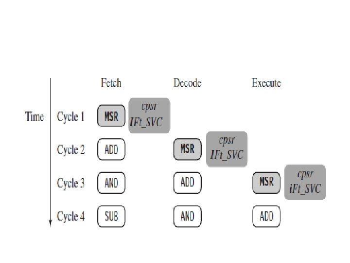
PIPELINED INSTRCUTION SEQUENCE
CONTD. .
Pipeline Executing Characteristics • The ARM pipeline has not processed an instruction until it passes completely through the execute stage. For example, an ARM 7 pipeline (with three stages) has executed an instruction only when the fourth instruction is fetched. • The MSR instruction is used to enable IRQ interrupts, which only occurs once the MSR instruction completes the execute stage of the pipeline. It clears the I bit in the cpsr to enable the IRQ interrupts. • Once the ADD instruction enters the execute stage of the pipeline, IRQ interrupts are enabled.
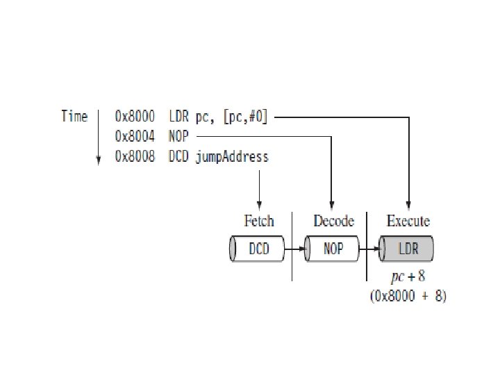
CONTD. . • In the execute stage, the pc always points to the address of the instruction plus 8 bytes. In other words, the pc always points to the address of the instruction being executed plus two instructions ahead. • This is important when the pc is used for calculating a relative offset and is an architectural characteristic across all the pipelines. Note when the processor is in Thumb state the pc is the instruction address plus 4.
THREE CHARACTERISTICS OF PIPELINING • First, the execution of a branch instruction or branching by the direct modification of the pc causes the ARM core to flush its pipeline. • Second, ARM 10 uses branch prediction, which reduces the effect of a pipeline flush by predicting possible branches and loading the new branch address prior to the execution of the instruction. • Third, an instruction in the execute stage will complete even though an interrupt has been raised. Other instructions in the pipeline will be abandoned, and the processor will start filling the pipeline from the appropriate entry in the vector table.
Exception Handling When an exception occurs, the ARM: Copies CPSR into SPSR_<mode> Sets appropriate CPSR bits: Changes to ARM state Changes to related mode Disables IRQ Disables FIQ (only on fast interrupts) Stores the return address in LR_<mode> Sets PC to vector address To return, exception handler needs to: Restore CPSR from SPSR_<mode> Restore PC from LR_<mode> This can only be done in ARM state. 0 x 0 C FIQ IRQ (Reserved) Data Abort Prefetch Abort 0 x 08 Software Interrupt 0 x 04 Undefined Instruction 0 x 00 Reset 0 x 1 C 0 x 18 0 x 14 0 x 10 Vector Table
EXCEPTIONS, INTERRUPTS & VECTOR TABLE • When an exception or interrupt occurs, the processor sets the PC to a specific memory address. The address is within a special address range called the vector table. • The entries in the vector table are instructions that branch to specific routines designed to handle a particular exception or interrupt. • When an exception or interrupt occurs, the processor suspends normal execution and starts loading instructions from the exception vector table. Each vector table entry contains a form of branch instruction pointing to the start of a specific routine.
THE VECTOR TABLE
• Reset vector is the location of the first instruction executed by the processor when power is applied. This instruction branches to the initialization code. • Undefined instruction vector is used when the processor cannot decode an instruction. • Software interrupt vector is called when you execute a SWI instruction. The SWI instruction is frequently used as the mechanism to invoke an operating system routine. • Prefetch abort vector occurs when the processor attempts to fetch an instruction from an address without the correct access permissions. The actual abort occurs in the decode stage. • Data abort vector is similar to a prefetch abort but is raised when an instruction attempts to access data memory without the correct access permissions. • Interrupt request vector is used by external hardware to interrupt the normal execution flow of the processor. It can only be raised if IRQs are not masked in the cpsr.
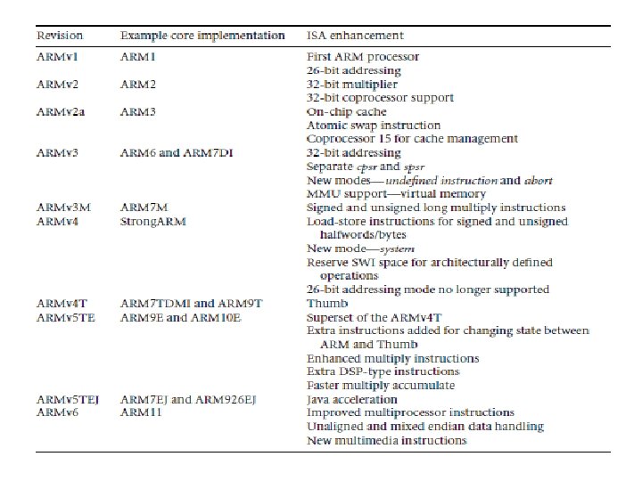
Architecture Revisions Nomenclature ARM{x} {y} {z} {T} {D} {M} {I} {E} {J} {F} {S} x—Family y—Memory management/protection unit z—Cache T—Thumb 16 -bit decoder D—JTAG debug M—Fast multiplier I—Embedded ICE E—Enhanced instructions (assumes TDMI) J—Jazelle State F—Vector floating-point unit S—Synthesizible version