
Embedded Systems Programming ARM programmers model and assembler
Embedded Systems Programming ARM programmer’s model and assembler
Memory Formats • The ARM views memory as a linear collection of bytes numbered upwards from zero. Bytes 0 to 3 hold the first stored word, bytes 4 to 7 the second and so on. The ARM can treat words in memory as being stored either in Big Endian or Little Endian format. • A word is 32 bits • Addresses are 32 bits
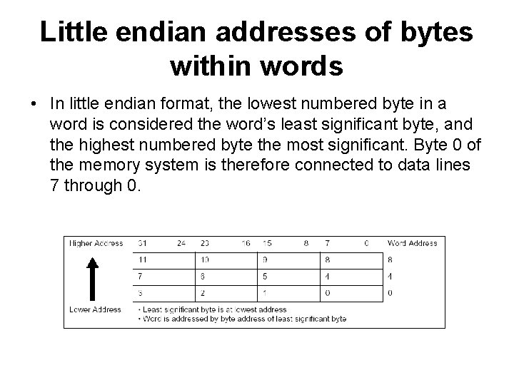
Little endian addresses of bytes within words • In little endian format, the lowest numbered byte in a word is considered the word’s least significant byte, and the highest numbered byte the most significant. Byte 0 of the memory system is therefore connected to data lines 7 through 0.
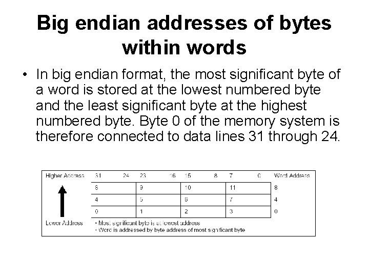
Big endian addresses of bytes within words • In big endian format, the most significant byte of a word is stored at the lowest numbered byte and the least significant byte at the highest numbered byte. Byte 0 of the memory system is therefore connected to data lines 31 through 24.
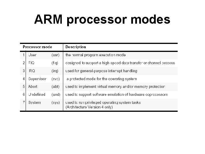
ARM processor modes

The ARM register set

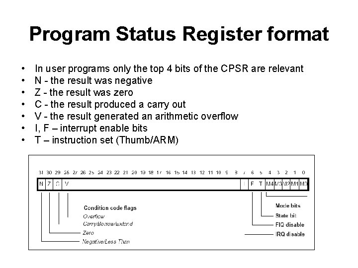
Program Status Register format • • In user programs only the top 4 bits of the CPSR are relevant N - the result was negative Z - the result was zero C - the result produced a carry out V - the result generated an arithmetic overflow I, F – interrupt enable bits T – instruction set (Thumb/ARM)
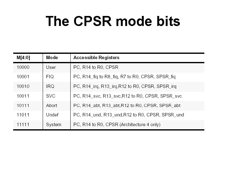
The CPSR mode bits
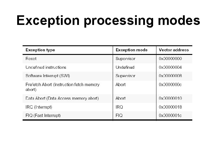
Exception processing modes
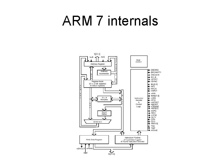
ARM 7 internals
The ARM instruction set • a) Data processing instructions • b) Data transfer instructions • c) Control flow & conditional execution • d) Special instructions
Data processing instructions • ALL operands are 32 -bits wide and either: • come from registers, or are literals (´immediate´ values ) specified in the instruction • The result, if any, is 32 -bits wide and goes into a register – except long multiplies generate 64 -bit results • All operand result registers are specified independently
- Slides: 13