Software Modeling and Design UNIT 1 1 Contents


- Slides: 189

Software Modeling and Design UNIT 1 1

Contents in Unit 1 • Introduction to software design • Design methods- procedural / structural and object oriented • Requirement Vs Analysis Vs Architecture Vs Design Vs Development • 4+1 Architecture • UP • COMET use case based software life cycle • Introduction to UML -Basic building blocks • Use case modeling, Use case template 2

• Introduction to software design, design methods- procedural / structural and object oriented, Requirement Vs Analysis Vs Architecture Vs Design Vs Development 4+1 Architecture, case study of transferring requirement to design, UP, COMET use case based software life cycle, Introduction to UML -Basic building blocks, Reusability, Use case modeling, Use case template • Case study – Transferring requirements into design using advanced tool 3

• Model M: Abstractions from (really existing or only thought of ) things, people , processes and relationships between these abstractions. • To make predictions about the future • A model is always an approximation 4

Models of models. . . • Modeling is relative. We can think of a model as reality and can build another model from it (with additional abstractions). M 2 Analysis M 1 Requirements Elicitation R …. f. M 2 I 2 f. M 1 I 1 f. R The development of Software-Systems is a Transformation of Models: Analysis, Design, Implementation, Testing R 5

Systems Development Life Cycle (SDLC) • Systems development project – Planned undertaking with fixed beginning and end – Produces desired result or product • Successful development project: – Provides a detailed plan to follow – Organized, methodical sequence of tasks and activities – Produces reliable, robust, and efficient system 6

Start of lecture. 15 Jan 2018 7

Phases of the Systems Development Lifecycle (SDLC) 8

SDLC (cont. . ) • Project planning: Initiate, ensure feasibility, plan schedule, obtain approval for project • Analysis: Understand business needs and processing requirements • Design: Define solution system based on requirements and analysis decisions • Implementation: Construction, testing, user training, and installation of new system • Support: Keep system running and improve 9

SDLC and problem-solving • Similar to problem-solving approach – Organization recognizes problem (Project Planning) – Project team investigates, understands problem and solution requirements (Analysis) – Solution is specified in detail (Design) – System that solves problem built and installed (Implementation) – System used, maintained, and enhanced to continue to provide intended benefits (Support) 10

1. Software Design • Software Design is the process by which an agent creates a specification of a software artifact, • intended to accomplish goals, • using a set of primitive components and • subject to constraints. 11

• e. g. of artifacts: • use cases, class diagrams, and • other Unified Modeling Language (UML) models, • requirements and design documents 12

2. Software Design Notation • A software design notation is a means of describing a software design either graphically or textually, or both. For example: class diagrams are a graphical design notation, and pseudocode is a textual design notation. 13

A design notation suggests a particular approach for performing a design; however, it does not provide a systematic approach for producing a design. 14

3. Software Design Concept • A software design concept is a fundamental idea that can be applied to designing a system. • For example, • Information hiding is a software design concept. 15

4. Software Design Strategy • A software design strategy is an overall plan and direction for developing a design. • For example, • object-oriented decomposition is a software design strategy. 16

3. Software Design Method • A software design method is a systematic approach that describes the sequence of steps to follow in order to create a design, given the software requirements of the application. • It helps a designer or design team identify the design decisions to be made, the order in which to make them, and the structuring criteria to use in making them. • A design method is based on a set of design concepts, employs one or more design strategies, and documents 17 the resulting design, using a design notation

• Contd… from SDLC ANALYSIS VS DESIGN PHASE 18

Analysis Phase of SDLC • Gather information to learn problem domain • Define system requirements • Build prototypes for discovery of requirements • Prioritize requirements • Generate and evaluate alternatives • Review recommendations with management 19

Design Phase of SDLC • Design and integrate the network • Design the application architecture • Design the user interfaces • Design the system interfaces • Design and integrate the database • Prototype for design details 20

Transition from Analysis to Design 21

Transition from Analysis to Design Analysis: A process of extracting and organizing user requirements and establishing an accurate model of the problem domain. (WHAT) Design: Process of mapping requirements to a system implementation that conforms to desired cost, performance, and quality parameters. (HOW) 22

Transition from analysis to Design • Blurred line between analysis & design • Process of design leads to better understanding of requirements • Can be performed iteratively • No direct & obvious mapping exists between structured analysis and structured design. 23

Two Approaches for Analysis & Design • Traditional Approach: SSAD(System Structured Analysis and Design) • Structured Analysis (SA), resulting in a logical design, drawn as a set of data flow diagrams • Structured Design (SD) transforming the logical design into a program structure drawn as a set of structure charts • OOAD • Designing systems using self-contained objects and object classes 24

Structured Analysis • Define what system needs to do (processing requirements) • Define data which the system needs to store and use (data requirements) • Define inputs and outputs • Define how functions work together to accomplish tasks • Data Flow Diagrams and Entity Relationship Diagrams show results of Structured Analysis 25

DFD • Better understanding of the functions of the systems could be obtained by considering the flow of data through the system. • DFDs start at a high level of abstraction and proceed to more detailed levels 26

• There are essentially two different types of notations for data flow diagrams (Yourdon & Coad or Gane & Sarson) defining different visual representations for processes, data stores, data flow and external entities. • Yourdon and Coad type data flow diagrams are usually used for system analysis and design, while Gane and Sarson type DFDs are more common for visualizing information systems. • Visually, the biggest difference between the two ways of drawing data flow diagrams is how processes look. In the Yourdon and Coad way, processes are depicted as circles, while in the Gane and Sarson diagram the processes are squares with rounded corners. 27

1. Process Notations. • A process transforms incoming data flow into outgoing data flow. 28

2. Datastore Notations • Datastores are repositories of data in the system. They are sometimes also referred to as files. 29

3. Dataflow Notations • Dataflows are pipelines through which packets of information flow. • Label the arrows with the name of the data that moves through it. 30

4. External Entity Notations • External entities are objects outside the system, with which the system communicates. • External entities are sources and destinations of the system's inputs and outputs. 31

• Level 0 • Level 1 • Level 2 32

Data Flow Diagram (DFD) created using Structured Analysis Technique 33

34

ERD • There are three basic elements in ERDiagrams: 35

• Entities are the "things" for which we want to store information. • An entity is a person, place, thing or event. • Attributes are the data we want to collect for an entity. • Relationships describe the relations between the entities. 36

• Name of the entity must be unique within this model. • In this case, the name of the entity is a name of type, rather than a specific instance of this type. • A concrete representative of the entity is called by the entity instance 37

Entity-Relationship Diagram (ERD) created using the Structured Analysis technique Crows foot notation 38

• Crow's Foot notation was proposed by Gordon Everest, originally called Inverted Arrow. • According to this notation, the entity is represented by rectangle containing its name. 39

Cardinality vs Modality • Cardinality refers to the maximum number of times an instance in one entity can be associated with instances in the related entity. • Modality refers to the minimum number of times an instance in one entity can be associated with an instance in the related entity. 40

• Cardinality can be 1 or Many and the symbol is placed on the outside ends of the relationship line, closest to the entity, • Modality can be 1 or 0 and the symbol is placed on the inside, next to the cardinality symbol. • For a cardinality of 1 a straight line is drawn. • For a cardinality of Many a foot with three toes is drawn. • For a modality of 1 a straight line is drawn. • For a modality of 0 a circle is drawn. 41

42

Cardinality using Crows Foot Notation ONE Artist (can) perform "zero, one, or many" song(s). 43

44

Structure Chart Created Using Structured Design Technique 45

Structure Chart (SC) • A Structure Chart (SC) in software engineering and organizational theory is a chart which shows the breakdown of a system to its lowest manageable levels. • They are used in structured programming to arrange program modules into a tree. • Each module is represented by a box, which contains the module's name. • The tree structure visualizes the relationships between modules. [3] 46

• A structure chart is a top-down modular design tool, constructed of squares representing the different modules in the system, and lines that connect them. • The lines represent the connection and or ownership between activities and subactivities 47

• In structured analysis structure charts, according to Wolber (2009), "are used to specify the highlevel design, or architecture, of a computer program. As a design tool, they aid the programmer in dividing and conquering a large software problem, that is, recursively breaking a problem down into parts that are small enough to be understood by a human brain. The process is called top-down design, or functional decomposition. Programmers use a structure chart to build a program in a manner similar to how an architect uses a blueprint to build a house. In the design stage, the chart is drawn and used as a way for the client and the various software designers 48

Structure Charts - Invocation / Call • • Call of subordinate module Connector element NOT a data flow One specific form of control flow Has a direction No split or join No label 49

50

Structure Charts - Sequence of Execution • Sequence of subordinate modules in the diagram is not reflecting a binding sequence of invocation • Sequence of invocation is defined in the specification of the super-ordinate module • Module specification is the decisive element 51

52

Structure Charts - Data Flow • • • Flow of information Data transfer Bound to invocation Has a direction No splits or joins Label: noun 53

Structure Charts - Control Flow • Flow of control (<> invocation) ==> control execution path of targeted module • Bound to invocation • Has a direction • No splits or joins • Label: flag, decision, condition 54

Structure Charts - Data Store • Storage for permanent data • Database / file • Passive; no activity beyond basic retrieval capacity • Serviced by a module • Label: noun • Specified in data-dictionary and/or with an ERdiagram label Data store 55

56

Structured Analysis Leads to Structured Design and Structured Programming 57

Structured programming • Structured programming is a programming paradigm aimed at improving the clarity, quality, and development time of a computer program by making extensive use of subroutines, block structures, for and while loops—in contrast to using simple tests and jumps such as the go to statement, which could lead to "spaghetti code" that is difficult to follow and maintain 58

Two Approaches for Analysis & Design • Traditional Approach: SSAD(System Structured Analysis and Design) • Structured Analysis (SA), resulting in a logical design, drawn as a set of data flow diagrams • Structured Design (SD) transforming the logical design into a program structure drawn as a set of structure charts • OOAD • Designing systems using self-contained objects and classes 59

OOAD methods Three major steps: 1. Identify the objects 2. Determine their attributes and services 3. Determine the relationships between objects 60

Object-Oriented Approach • Views information system as collection of interacting objects that work together to accomplish tasks • OOA • OOD • OOP 61

Object Oriented Analysis (OOA) – Defines types of objects that do work of system – Shows how objects interact with users to complete tasks 62

Object-oriented analysis • The purpose of any analysis activity in the software life-cycle is to create a model of the system's functional requirements that is independent of implementation constraint 63

• The primary tasks in OOA are: • • • Find the objects Organize the objects Describe how the objects interact Define the behavior of the objects Define the internals of the objects Common models used in OOA are use cases and object models 64

Object Oriented Design • OOD is the process of planning a system of interacting objects for the purpose of solving a software problem. • It is one approach to software design. 65

– Defines object types needed to communicate with people and devices in system – Shows how objects interact to complete tasks – Refines each type of object for implementation with specific language of environment 66

Deliverables of OOD • Sequence diagram • Class diagram 67

Object Oriented Programming (OOP) – Writing statements in programming language 69

General Advantages • Understandable – maps the “real-world” objects more directly – manages complexity via abstraction and encapsulation • Practical – successful in real applications – suitable to many, but not all, domains • Productive – experience shows increased productivity over life-cycle – encourages reuse of model, design, and code • Stable – changes minimally perturb objects 70

Phase Structured Object Oriented Analysis Structuring Requirements • DFDs • ER Analysis • Decision Tree Requirements Engg • Use Case Modelling • Analysis Modelling (Static & Dynamic) Design • DB Design • GUI Design • Design System Architecture • Design Classes • GUI Design 71

The Unified Process (UP) 72

The Unified Process (UP) • Object-oriented development approach • Offered by IBM / Rational – Booch, Rumbaugh, Jacobson • Unified Modeling Language (UML) used primarily for modeling • UML can be used with any OO methodology • UP defines 4 life cycle phases – Inception, elaboration, construction, transition 73

The Unified Process (UP) (continued) • Reinforces six best practices – Develop iteratively – Define and manage system requirements – Use component architectures – Create visual models – Verify quality – Control changes 74

Phases in UP is divided into four phases • Inception • Elaboration • Construction • Transition 75

Iterations Each phase has iterations, each having the purpose of producing a demonstrable piece of software. The duration of iteration may vary from two weeks or less up to six months. Iterations Inception Iterations Elaboration Iterations Construction Iterations Transition 76

The Iterations and the phases 77

78

Workflow: Is defined as the repeatable pattern of business activity enabled by the systematic organization of resources into processes that transform the materials, provide services, or process the information. 79

Inception • The life-cycle objectives of the project are stated, so that the needs of every stakeholder are considered. • Scope and boundary conditions, acceptance criteria and some requirements are established. 80

Elaboration • An analysis is done to determine the risks, stability of vision of what the product is to become, stability of architecture and expenditure of resources. • Define the architecture. § Validate the architecture. 81

Construction • The Construction phase is a manufacturing process. • It emphasizes managing resources and controlling operations to optimize costs, schedules and quality. • Develop and test components. • Manage resources and control process. • Assess the iteration 82

Transition • The transition phase is the phase where the product is put in the hands of its end users. • It involves issues of marketing, packaging, installing, configuring, supporting the usercommunity, making corrections, etc. 83

UP over 84

COMET 85

What is COMET? • Concurrent Object Modeling and architectural design m. EThod • COMET is a design method for UML supporting OO systems – Concurrent – Distributed – Real-Time • Compatible with USDP (Unified Software Development Process) 86

COMET Software Lifecycle • A highly iterative process • Focuses on the use case concept – Functional requirements are recorded in terms of actors and their use of the system, collected into use cases. – A use case is a series of interactions between one or more actors and the system 87

COMET Software Lifecycle 88

COMET Modeling • 1. Requirements Modeling – Use cases are generated, and serve as the requirements for the system. – Throwaway prototypes can help to clarify the requirements. 89

2. Analysis Modeling Static Models Class Diagrams show the classes of the problem domain. Dynamic Models Show the problem domain objects participating in use cases. 90

3. Design Modeling – Software architecture is designed – Problem Domain (Analysis Mode) is mapped to Solution Domain (Design Model) – Subsystems are identified and structured • Emphasis is on designing distributed subsystems as configurable components that communicate with each other via messaging. 91

3. Incremental Prototyping • After modeling, the software subsystems are incrementally constructed and integrated into incremental prototypes. • A phased, iterative approach – Build and test a little at a time. 92

4. Incremental Software Construction • Incremental Software Construction consists of – Detailed design – Coding – Unit testing 93

5. Incremental Software Integration • Integration testing of each software is performed • Integration test for the increment – based on the use cases selected – developed for each use case – Is type of white box testing (between object interfaces) – Yields incremental prototype, formed by a software increment • Verified, integrated, then reiterated 94

6. System Testing • When the incremental prototype is to be turned over to the customer, it must first undergo system testing. • The use cases of the requirements model are tested black box, ensuring the software meets specifications. 95

COMET ends…. 96

UML 97

What is UML? • Unified Modeling Language – OMG Standard, Object Management Group – Based on work from Booch, Rumbaugh, Jacobson • UML is a modeling language to express and design documents, software – Particularly useful for OO design – Independent of implementation language 98

Object Management Group (OMG) • Is an international, open membership, not-forprofit technology standards consortium. • OMG Task Forces develop enterprise integration standards for a wide range of technologies and industries. 0 OMG modeling standards enable visual design, execution and maintenance of software and other processes. Originally aimed at standardizing distributed object-oriented systems, the company now focuses on modeling (programs, systems and business processes) and model-based standards 99

Why use UML • Open Standard, Graphical notation for – Specifying, visualizing, constructing, and documenting software systems • Language can be used from general initial design to very specific detailed design across the entire software development lifecycle • Increase understanding/communication of product to customers and developers 100

• Support for diverse application areas • Support for UML in many software packages today (e. g. Rational, plugins for popular IDE’s like Net. Beans, Eclipse) • Based upon experience and needs of the user community 101

Brief History • Flooded with methodologies in early 90’s – Booch, Jacobson, Yourden, Rumbaugh • Booch, Jacobson merged methods 1994 • Rumbaugh joined 1995 • 1997 UML 1. 1 from OMG includes input from others, e. g. Yourden • UML v 2. 0 current version 102

History of UML 103

• OMT : Object Modeling Technique • OOSE: Object-Oriented Software Engineering • OOPSLA: Object-Oriented Programming, Systems, Languages, and Applications. 104

Contributions to UML 105

Systems, Models and Views • A model is an abstraction describing a subset of a system • A view depicts selected aspects of a model • A notation is a set of graphical or textual rules for depicting views • Views and models of a single system may overlap each other Examples: • System: Aircraft • Models: Flight simulator, scale model • Views: All blueprints, electrical wiring, fuel system 106

4+1 View Model of Architecture 109

4+1 View Model of Architecture End user Logical view Development view Programmers & software managers Scenarios Process View Integrator Physical View System Engineer 110

Logical View (Object-oriented Decomposition) Viewer: End-user considers: Functional requirements- What the system should provide in terms of services to its users. Notation: The Booch notation (OMT) (object and dynamic models) Tool: Rational Rose 111

Process View (The process decomposition) viewer: Integrators considers: Non - functional requirements (concurrency, performance, scalability) style: Several styles would fit in this view (Garlan and Shaw ‘s Architecture styles) 112

Process view (cont. ) • Uses multiple levels of abstractions, a logical network of processes at the highest level • A process is a grouping of tasks that form an executable unit: – Major Tasks: Arch. relevant tasks – Minor Tasks: Helper tasks. (Buffering) 113

Development View (Subsystem decomposition) Basis of a line of product Viewer: Programmers and Software Managers considers: software module organization (Hierarchy of layers, software management, reuse, constraints of tools) Style: layered style Notation: the Booch notation (module, subsystem, layer) 114

Physical View (Mapping the software to the Hardware) Viewer: System Engineers Considers: Non-functional req. regarding to underlying hardware (Topology, Communication) Notation: May have several forms and may Tightly connected to the process view • There may be two architecture: – Test and development – deployment 115

4+1 View Model of Architecture over…. . 116

Models, Views, Diagrams 117

UML Diagrams 118

119

INTRODUCTION TO UML 120

A Conceptual Model of the UML • BASIC BUILDING BLOCKS 121

BASIC BUILDING BLOCKS • The vocabulary of the UML encompasses three kinds of building blocks: • 1. Things • 2. Relationships • 3. Diagrams • Things are the abstractions that are first-class citizens in a model; • Relationships tie these things together; • Diagrams group interesting collections of things. 122

1. Things in the UML There are four kinds of things in the UML: 1. Structural things 2. Behavioral things 3. Grouping things 4. Annotational things These things are the basic object-oriented building blocks of the UML. You use them to write well-formed models. 123

A. Structural Things • Structural things are the nouns of UML models. • These are the mostly static parts of a model, representing elements that are either conceptual or physical. • In all, there are seven kinds of structural things. 124

A 1. CLASS • A class is a description of a set of objects that share the same attributes, operations, relationships, and semantics. • A class implements one or more interfaces. • Graphically, a class is rendered as a rectangle, usually including its name, attributes, and operations 125

126

A 2. Interface • Is a collection of operations that specify a service of a class or component. • An interface therefore describes the externally visible behavior of that element. • An interface might represent the complete behavior of a class or component or only a part of that behavior. • An interface defines a set of operation specifications (that is, their signatures) but never a set of operation implementations. 127

• Graphically, an interface is rendered as a circle together with its name. An interface rarely stands alone. Rather, it is typically attached to the class or component that realizes the interface. 128

A 3. Collaboration • Defines an interaction and is a society of roles and other elements that work together to provide some cooperative behavior that's bigger than the sum of all the elements. • Therefore, collaborations have structural, as well as behavioral, dimensions. • A given class might participate in several collaborations 129

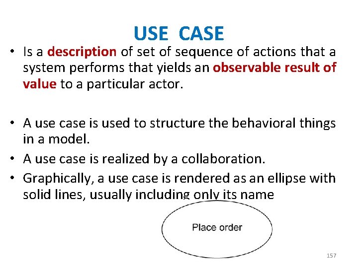
A 4. USE CASE • Is a description of set of sequence of actions that a system performs that yields an observable result of value to a particular actor. • A use case is used to structure the behavioral things in a model. • A use case is realized by a collaboration. • Graphically, a use case is rendered as an ellipse with solid lines, usually including only its name 130

A 5. Active Class • Is a class whose objects own one or more processes or threads and therefore can initiate control activity. • An active class is just like a class except that its objects represent elements whose behavior is concurrent with other elements. • Graphically, an active class is rendered just like a class, but with heavy lines, usually including its name, attributes, and operations 131

• The previous five things represent conceptual or logical things, following 2 are Physical Things 132

A 6. Component • Is a physical and replaceable part of a system that conforms to and provides the realization of a set of interfaces. • A component typically represents the physical packaging of otherwise logical elements, such as classes, interfaces, and collaborations. • Graphically, a component is rendered as a rectangle with tabs, usually including only its name 133

A 7. Node • Is a physical element that exists at run time and represents a computational resource, generally having at least some memory and, often, processing capability. • A set of components may reside on a node and may also migrate from node to node. • Graphically, a node is rendered as a cube, usually including only its name 134

1. Things in the UML There are four kinds of things in the UML: 1. Structural things 2. Behavioral things 3. Grouping things 4. Annotational things These things are the basic object-oriented building blocks of the UML. You use them to write well-formed models. 135

B. Behavioral things • Interaction − Interaction is defined as a behavior that consists of a group of messages exchanged among elements to accomplish a specific task. 136

• State machine − • State machine is useful when the state of an object in its life cycle is important. • It defines the sequence of states an object goes through in response to events. Events are external factors responsible for state change 137

1. Things in the UML There are four kinds of things in the UML: 1. Structural things 2. Behavioral things 3. Grouping things 4. Annotational things These things are the basic object-oriented building blocks of the UML. You use them to write well-formed models. 138

C. Grouping things • Grouping things can be defined as a mechanism to group elements of a UML model together. There is only one grouping thing available − Package − Package is the only grouping thing available for gathering structural and behavioral things. 139

140

1. Things in the UML There are four kinds of things in the UML: 1. Structural things 2. Behavioral things 3. Grouping things 4. Annotational things These things are the basic object-oriented building blocks of the UML. You use them to write well-formed models. 141

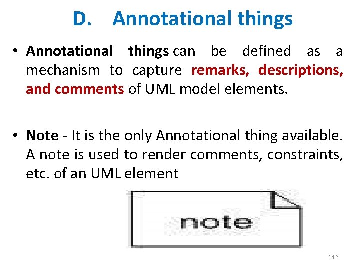
D. Annotational things • Annotational things can be defined as a mechanism to capture remarks, descriptions, and comments of UML model elements. • Note - It is the only Annotational thing available. A note is used to render comments, constraints, etc. of an UML element 142

1. Things in the UML There are four kinds of things in the UML: 1. Structural things 2. Behavioral things 3. Grouping things 4. Annotational things 143

BASIC BUILDING BLOCKS • The vocabulary of the UML encompasses three kinds of building blocks: • 1. Things • 2. Relationships • 3. Diagrams • Things are the abstractions that are first-class citizens in a model; • Relationships tie these things together; • Diagrams group interesting collections of things. 144

2. Relationships • There are four kinds of relationships in the UML: • • 1. Dependency 2. Association 3. Generalization 4. Realization 145

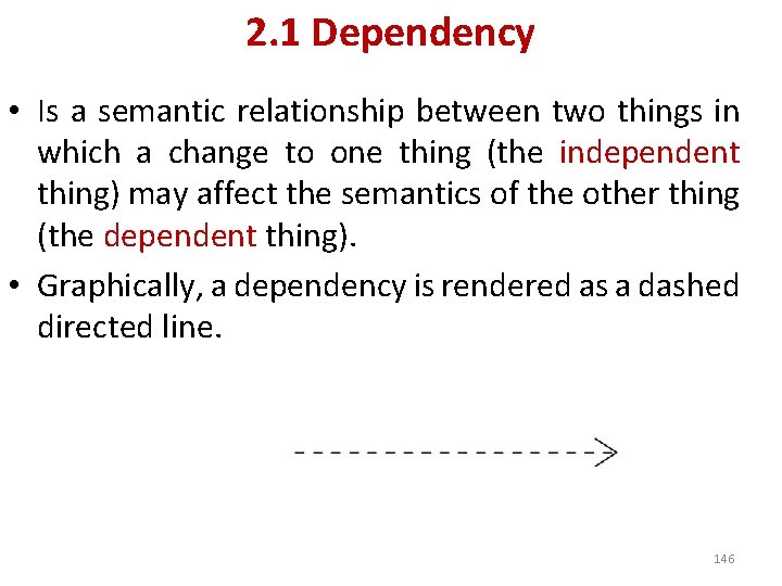
2. 1 Dependency • Is a semantic relationship between two things in which a change to one thing (the independent thing) may affect the semantics of the other thing (the dependent thing). • Graphically, a dependency is rendered as a dashed directed line. 146

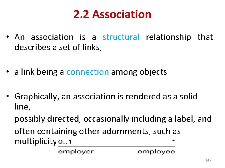
2. 2 Association • An association is a structural relationship that describes a set of links, • a link being a connection among objects • Graphically, an association is rendered as a solid line, possibly directed, occasionally including a label, and often containing other adornments, such as multiplicity and role names 147

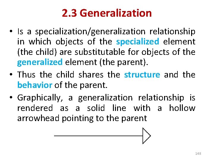
2. 3 Generalization • Is a specialization/generalization relationship in which objects of the specialized element (the child) are substitutable for objects of the generalized element (the parent). • Thus the child shares the structure and the behavior of the parent. • Graphically, a generalization relationship is rendered as a solid line with a hollow arrowhead pointing to the parent 148

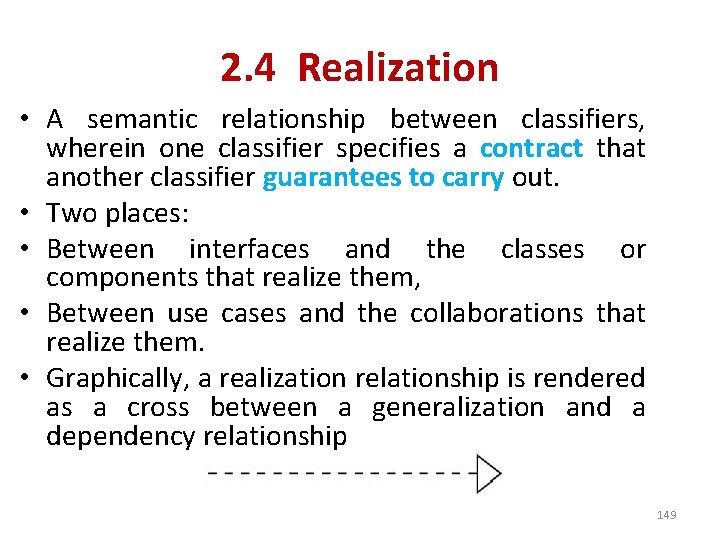
2. 4 Realization • A semantic relationship between classifiers, wherein one classifier specifies a contract that another classifier guarantees to carry out. • Two places: • Between interfaces and the classes or components that realize them, • Between use cases and the collaborations that realize them. • Graphically, a realization relationship is rendered as a cross between a generalization and a dependency relationship 149

2. Relationships • • 1. Dependency 2. Association 3. Generalization 4. Realization 150

BASIC BUILDING BLOCKS • The vocabulary of the UML encompasses three kinds of building blocks: • 1. Things • 2. Relationships • 3. Diagrams • Things are the abstractions that are first-class citizens in a model; • Relationships tie these things together; • Diagrams group interesting collections of things. 151

3. Diagrams • • • 1. Class diagram 2. Object diagram 3. Use case diagram 4. Sequence diagram 5. Collaboration diagram 6. Statechart diagram 7. Activity diagram 8. Component diagram 9. Deployment diagram 152

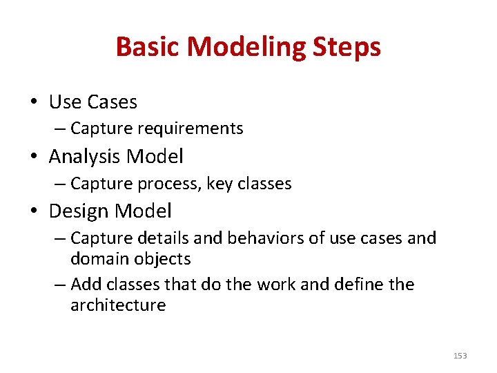
Basic Modeling Steps • Use Cases – Capture requirements • Analysis Model – Capture process, key classes • Design Model – Capture details and behaviors of use cases and domain objects – Add classes that do the work and define the architecture 153

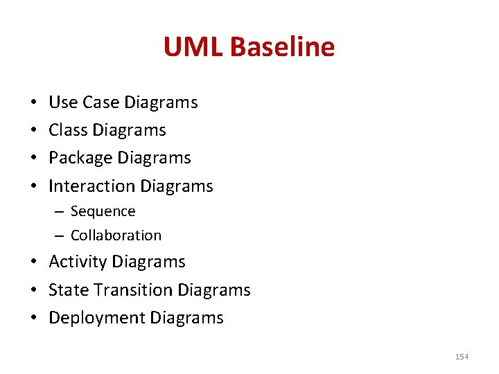
UML Baseline • • Use Case Diagrams Class Diagrams Package Diagrams Interaction Diagrams – Sequence – Collaboration • Activity Diagrams • State Transition Diagrams • Deployment Diagrams 154

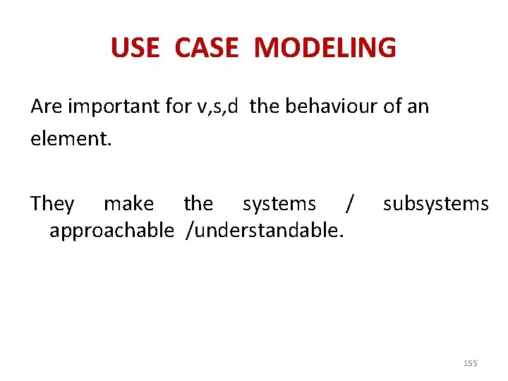
USE CASE MODELING Are important for v, s, d the behaviour of an element. They make the systems / approachable /understandable. subsystems 155

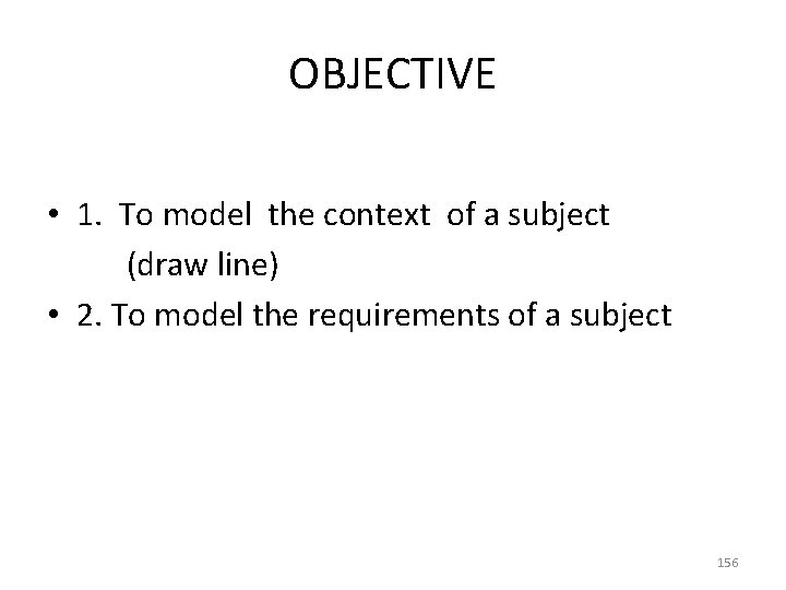
OBJECTIVE • 1. To model the context of a subject (draw line) • 2. To model the requirements of a subject 156

USE CASE • Is a description of set of sequence of actions that a system performs that yields an observable result of value to a particular actor. • A use case is used to structure the behavioral things in a model. • A use case is realized by a collaboration. • Graphically, a use case is rendered as an ellipse with solid lines, usually including only its name 157

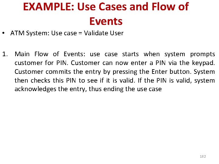
EXAMPLE: Use Cases and Flow of Events • ATM System: Use case = Validate User 1. Main Flow of Events: use case starts when system prompts customer for PIN. Customer can now enter a PIN via the keypad. Customer commits the entry by pressing the Enter button. System then checks this PIN to see if it is valid. If the PIN is valid, system acknowledges the entry, thus ending the use case 158

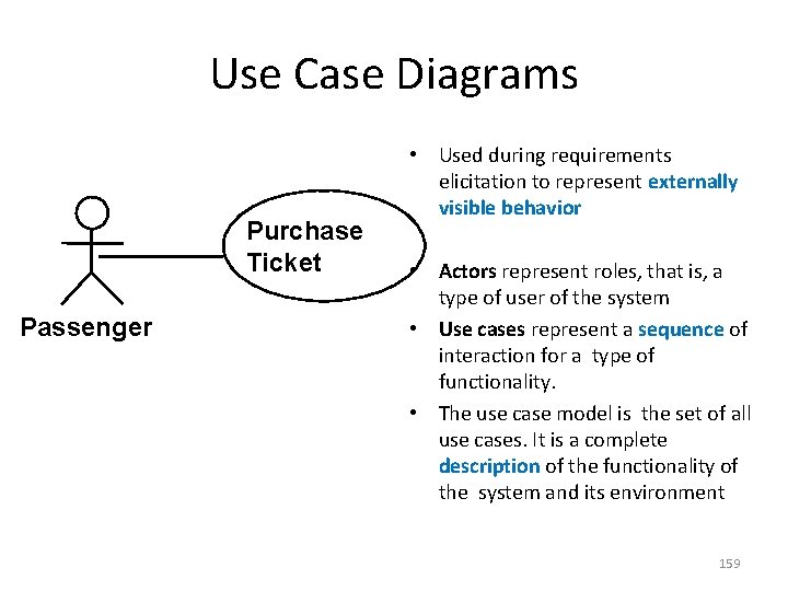
Use Case Diagrams Purchase Ticket Passenger • Used during requirements elicitation to represent externally visible behavior • Actors represent roles, that is, a type of user of the system • Use cases represent a sequence of interaction for a type of functionality. • The use case model is the set of all use cases. It is a complete description of the functionality of the system and its environment 159

• UCD to Activity Diagrams. • Scope of each use case 160

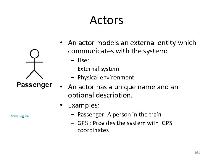
Actors • An actor models an external entity which communicates with the system: Passenger Stick Figure – User – External system – Physical environment • An actor has a unique name and an optional description. • Examples: – Passenger: A person in the train – GPS : Provides the system with GPS coordinates 161

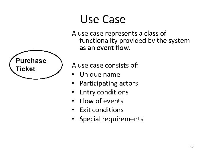
Use Case A use case represents a class of functionality provided by the system as an event flow. Purchase Ticket A use case consists of: • Unique name • Participating actors • Entry conditions • Flow of events • Exit conditions • Special requirements 162

Examples of use cases • Validate user • Register for course • Pay for course 163

164

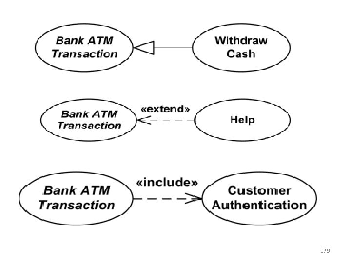
INCLUDE RELATIONSHIP • Use case include is a directed relationship between two use cases which is used to show that behavior of the included use case (the addition) is inserted into the behavior of the including (the base) use case. 165

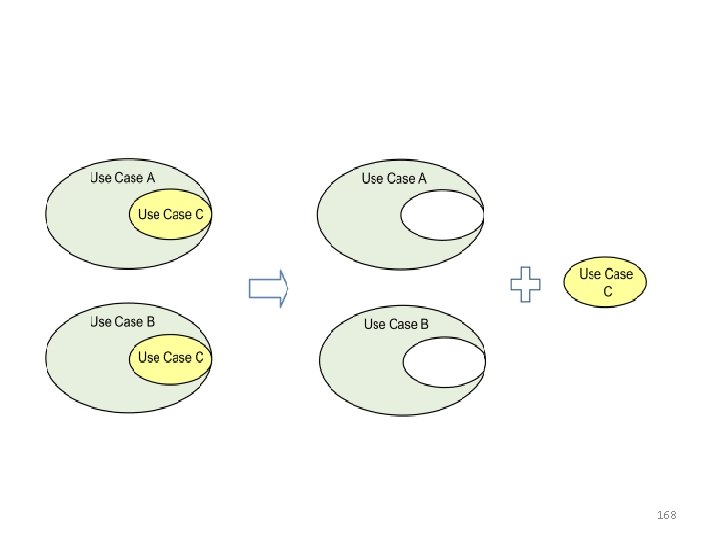
• The include relationship could be used: • to simplify large use case by splitting it into several use cases, • to extract common parts of the behaviors of two or more use cases. • A large use case could have some behaviors which might be detached into distinct smaller use cases to be included back into the base use case using the UML include relationship. • The purpose of this action is modularization of behaviors, making them more manageable. 166

Execution of the included use case is analogous to a subroutine call or macro command in programming. All of the behavior of the included use case is executed at a single location in the including use case before execution of the including use case is resumed. 167

168

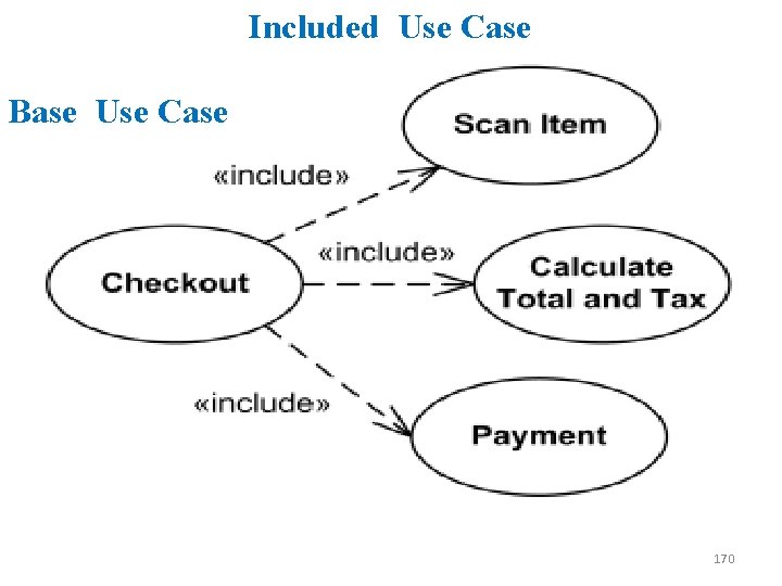
Include relationship between use cases is shown by a dashed arrow with an open arrowhead from the including (base) use case to the included (common part) use case. The arrow is labeled with the keyword «include» . 169

Included Use Case Base Use Case 170

• Large and complex Checkout use case has several use cases extracted, each smaller use case describing some logical unit of behavior. • Note, that including Checkout use case becomes incomplete by itself and requires included use cases to be complete. 171

172

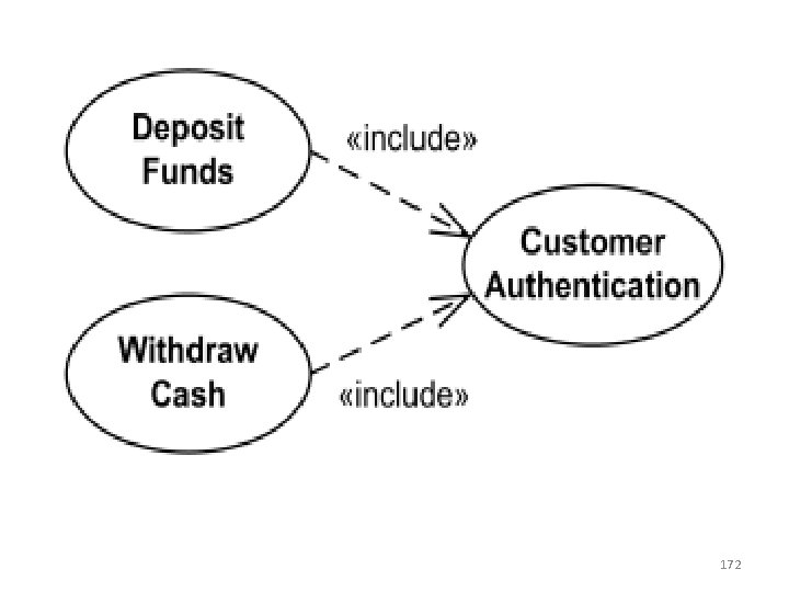
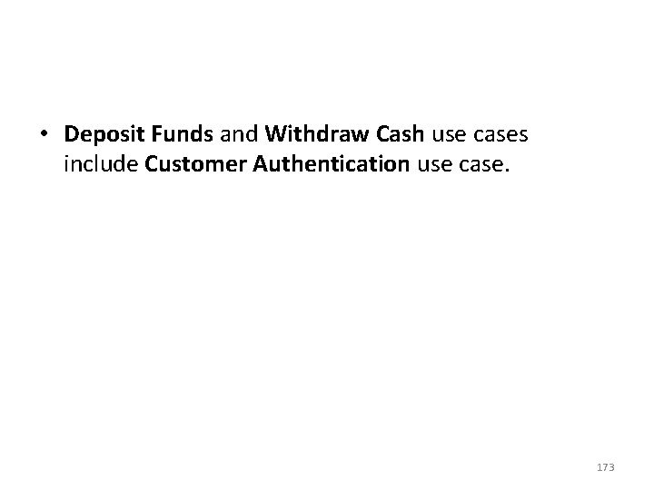
• Deposit Funds and Withdraw Cash use cases include Customer Authentication use case. 173

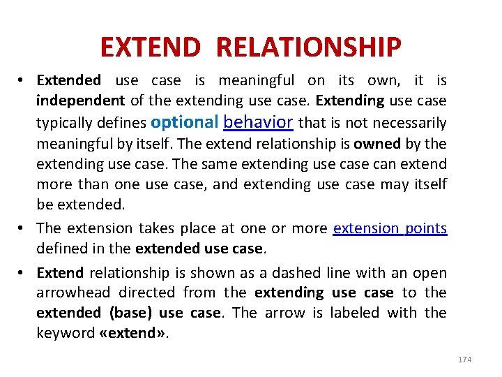
EXTEND RELATIONSHIP • Extended use case is meaningful on its own, it is independent of the extending use case. Extending use case typically defines optional behavior that is not necessarily meaningful by itself. The extend relationship is owned by the extending use case. The same extending use can extend more than one use case, and extending use case may itself be extended. • The extension takes place at one or more extension points defined in the extended use case. • Extend relationship is shown as a dashed line with an open arrowhead directed from the extending use case to the extended (base) use case. The arrow is labeled with the keyword «extend» . 174

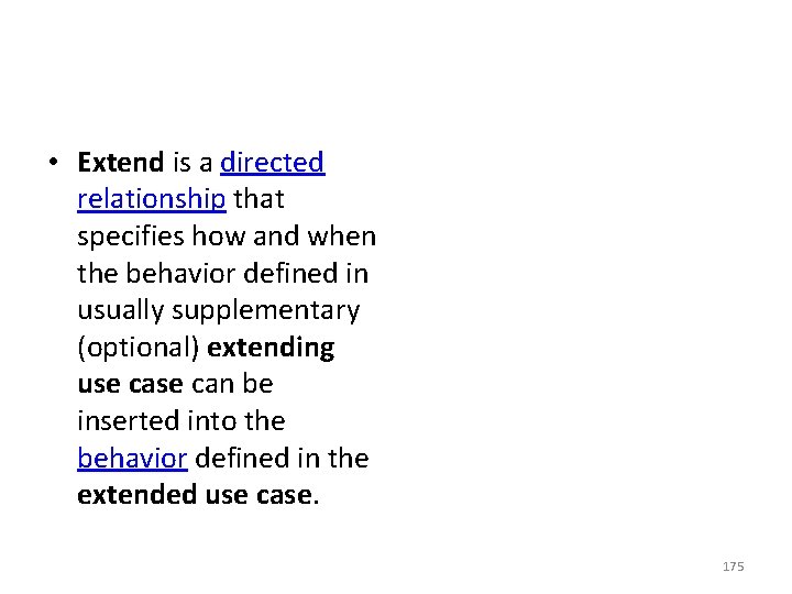
• Extend is a directed relationship that specifies how and when the behavior defined in usually supplementary (optional) extending use can be inserted into the behavior defined in the extended use case. 175

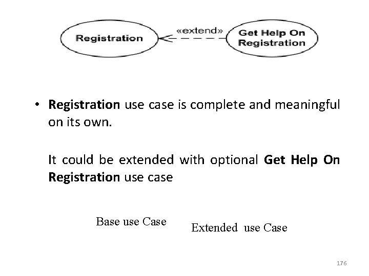
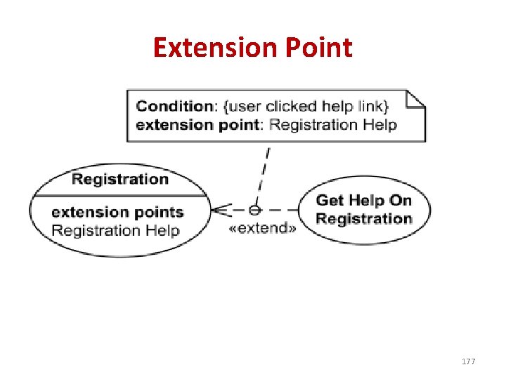
• Registration use case is complete and meaningful on its own. It could be extended with optional Get Help On Registration use case Base use Case Extended use Case 176

Extension Point 177

• The condition of the extend relationship as well as the references to the extension points are optionally shown in a comment note attached to the corresponding extend relationship. • An extension point is a feature of a use case which identifies (references) a point in the behavior of the use case where that behavior can be extended by some other (extending) use case, as specified by extend relationship. • Registration use case is conditionally extended by Get Help On Registration use case in extension point Registration Help. 178

179

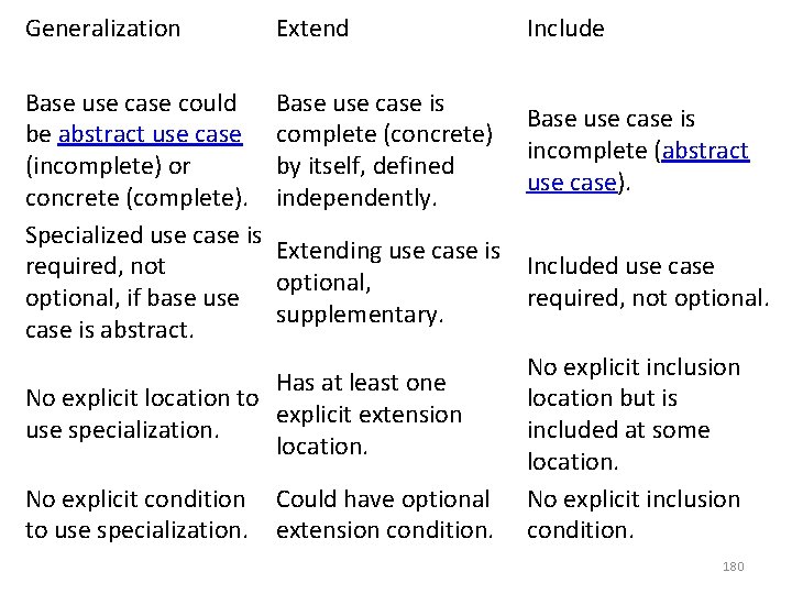
Generalization Extend Base use case could Base use case is be abstract use case complete (concrete) (incomplete) or by itself, defined concrete (complete). independently. Specialized use case is Extending use case is required, not optional, if base use supplementary. case is abstract. Include Base use case is incomplete (abstract use case). Included use case required, not optional. No explicit inclusion location but is included at some location. No explicit condition Could have optional No explicit inclusion to use specialization. extension condition. Has at least one No explicit location to explicit extension use specialization. location. 180

Use Cases and Flow of Events • ATM System: Use case = Validate User 1. Main Flow of Events: 2. Exceptional Flow of Events: 3. Exceptional Flow of Events: 4. Exceptional Flow of Events: 181

EXAMPLE: Use Cases and Flow of Events • ATM System: Use case = Validate User 1. Main Flow of Events: use case starts when system prompts customer for PIN. Customer can now enter a PIN via the keypad. Customer commits the entry by pressing the Enter button. System then checks this PIN to see if it is valid. If the PIN is valid, system acknowledges the entry, thus ending the use case 182

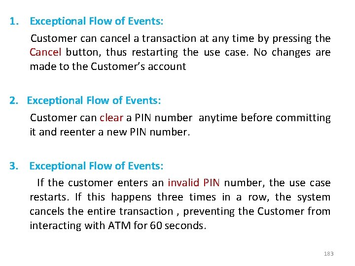
1. Exceptional Flow of Events: Customer cancel a transaction at any time by pressing the Cancel button, thus restarting the use case. No changes are made to the Customer’s account 2. Exceptional Flow of Events: Customer can clear a PIN number anytime before committing it and reenter a new PIN number. 3. Exceptional Flow of Events: If the customer enters an invalid PIN number, the use case restarts. If this happens three times in a row, the system cancels the entire transaction , preventing the Customer from interacting with ATM for 60 seconds. 183

SCENARIO • Each sequence representing one possible flow through all the variations in the use case • Instances are to classes, scenario is to Use Case 184

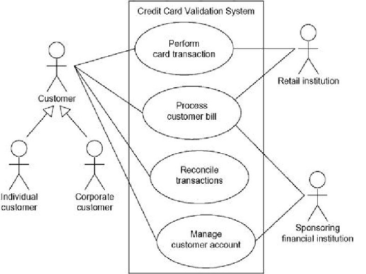
Use case diagrams commonly contain · Use cases · Actors · Dependency, generalization, and association relationships Like all other diagrams, use case diagrams may contain notes 185

Use Cases are useful to… • Determining requirements – New use cases often generate new requirements as the system is analyzed and the design takes shape. • Communicating with clients – Their notational simplicity makes use case diagrams a good way for developers to communicate with clients. • Generating test cases – The collection of scenarios for a use case may suggest a suite of test cases for those scenarios. 186

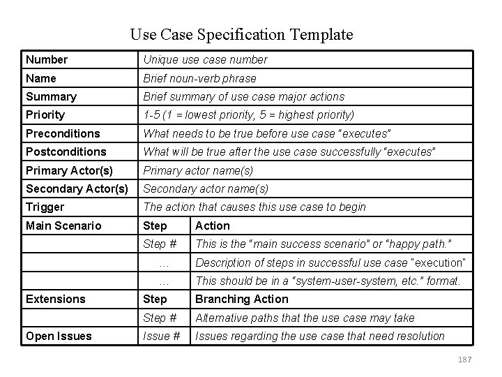
Use Case Specification Template Number Unique use case number Name Brief noun-verb phrase Summary Brief summary of use case major actions Priority 1 -5 (1 = lowest priority, 5 = highest priority) Preconditions What needs to be true before use case “executes” Postconditions What will be true after the use case successfully “executes” Primary Actor(s) Primary actor name(s) Secondary Actor(s) Secondary actor name(s) Trigger The action that causes this use case to begin Main Scenario Step Action Step # This is the “main success scenario” or “happy path. ” Extensions Open Issues … Description of steps in successful use case “execution” … This should be in a “system-user-system, etc. ” format. Step Branching Action Step # Alternative paths that the use case may take Issue # Issues regarding the use case that need resolution 187

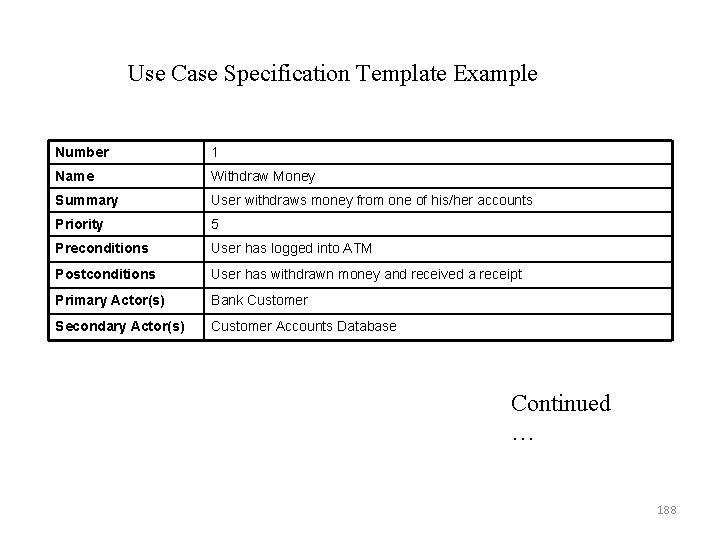
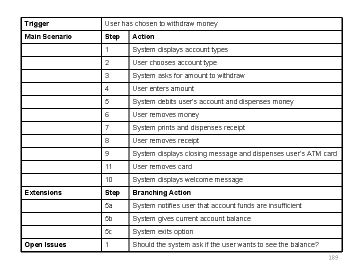
Use Case Specification Template Example Number 1 Name Withdraw Money Summary User withdraws money from one of his/her accounts Priority 5 Preconditions User has logged into ATM Postconditions User has withdrawn money and received a receipt Primary Actor(s) Bank Customer Secondary Actor(s) Customer Accounts Database Continued … 188

Trigger User has chosen to withdraw money Main Scenario Step Action 1 System displays account types 2 User chooses account type 3 System asks for amount to withdraw 4 User enters amount 5 System debits user’s account and dispenses money 6 User removes money 7 System prints and dispenses receipt 8 User removes receipt 9 System displays closing message and dispenses user’s ATM card 11 User removes card 10 System displays welcome message Step Branching Action 5 a System notifies user that account funds are insufficient 5 b System gives current account balance 5 c System exits option 1 Should the system ask if the user wants to see the balance? Extensions Open Issues 189

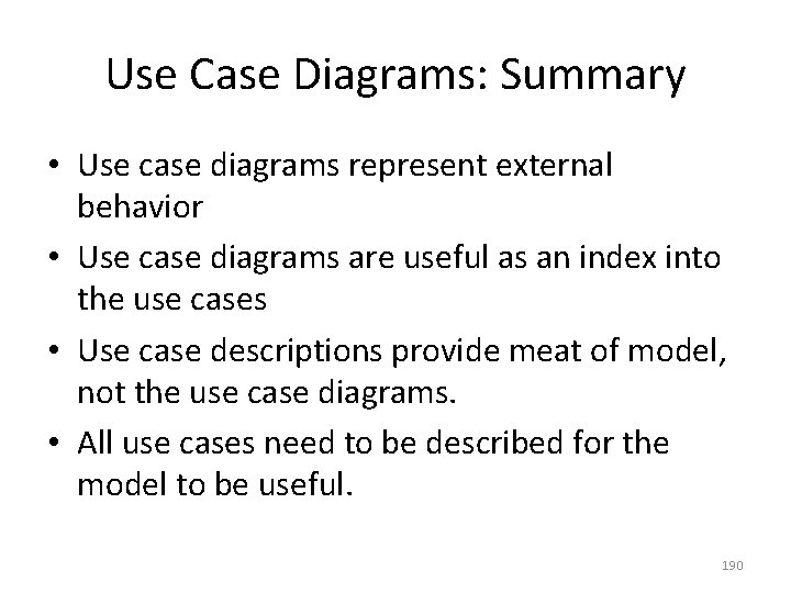
Use Case Diagrams: Summary • Use case diagrams represent external behavior • Use case diagrams are useful as an index into the use cases • Use case descriptions provide meat of model, not the use case diagrams. • All use cases need to be described for the model to be useful. 190

Read On…. . ( all basic concepts have been covered in class) Case study – Transferring requirements into design using advanced tool 191

END OF UNIT 1 192