Accelerator Physics Particle Acceleration G A Krafft Alex








- Slides: 117
Accelerator Physics Particle Acceleration G. A. Krafft, Alex Bogacz and Timofey Zolkin Jefferson Lab Colorado State University Lecture 6 USPAS Accelerator Physics June 2013
RF Acceleration • • Characterizing Superconducting RF (SRF) Accelerating Structures – Terminology – Energy Gain, R/Q, Q 0, QL and Qext RF Equations and Control – Coupling Ports – Beam Loading RF Focusing Betatron Damping and Anti-damping USPAS Accelerator Physics June 2013
Terminology 5 Cell Cavity 1 CEBAF Cavity “Cells” 9 Cell Cavity 1 DESY Cavity USPAS Accelerator Physics June 2013
Modern Jefferson Lab Cavities (1. 497 GHz) are optimized around a 7 cell design Typical cell longitudinal dimension: λRF/2 Phase shift between cells: π Cavities usually have, in addition to the resonant structure in picture: (1) At least 1 input coupler to feed RF into the structure (2) Non-fundamental high order mode (HOM) damping (3) Small output coupler for RF feedback control USPAS Accelerator Physics June 2013
USPAS Accelerator Physics June 2013
Some Fundamental Cavity Parameters • Energy Gain • For standing wave RF fields and velocity of light particles • Normalize by the cavity length L for gradient USPAS Accelerator Physics June 2013
Shunt Impedance R/Q • Ratio between the square of the maximum voltage delivered by a cavity and the product of ωRF and the energy stored in a cavity • Depends only on the cavity geometry, independent of frequency when uniformly scale structure in 3 D • Piel’s rule: R/Q ~100 Ω/cell CEBAF 5 Cell 480 Ω CEBAF 7 Cell 760 Ω DESY 9 Cell 1051 Ω USPAS Accelerator Physics June 2013
Unloaded Quality Factor • As is usual in damped harmonic motion define a quality factor by • Unloaded Quality Factor Q 0 of a cavity • Quantifies heat flow directly into cavity walls from AC resistance of superconductor, and wall heating from other sources. USPAS Accelerator Physics June 2013
Loaded Quality Factor • When add the input coupling port, must account for the energy loss through the port on the oscillation • Coupling Factor • It’s the loaded quality factor that gives the effective resonance width that the RF system, and its controls, see from the superconducting cavity • Chosen to minimize operating RF power: current matching (CEBAF, FEL), rf control performance and microphonics (SNS, ERLs) USPAS Accelerator Physics June 2013
Q 0 vs. Gradient for Several 1300 MHz Cavities Courtesey: Lutz Lilje USPAS Accelerator Physics June 2013
Eacc vs. time Courtesey: Lutz Lilje USPAS Accelerator Physics June 2013
RF Cavity Equations § § § § § Introduction Cavity Fundamental Parameters RF Cavity as a Parallel LCR Circuit Coupling of Cavity to an rf Generator Equivalent Circuit for a Cavity with Beam Loading • On Crest and on Resonance Operation • Off Crest and off Resonance Operation s Optimum Tuning s Optimum Coupling RF cavity with Beam and Microphonics Qext Optimization under Beam Loading and Microphonics RF Modeling Conclusions USPAS Accelerator Physics June 2013
Introduction § Goal: Ability to predict rf cavity’s steady-state response and develop a differential equation for the transient response § We will construct an equivalent circuit and analyze it § We will write the quantities that characterize an rf cavity and relate them to the circuit parameters, for a) a cavity b) a cavity coupled to an rf generator c) a cavity with beam USPAS Accelerator Physics June 2013
RF Cavity Fundamental Quantities § Quality Factor Q 0: § Shunt impedance Ra: § (accelerator definition); Va = accelerating voltage Note: Voltages and currents will be represented as complex quantities, denoted by a tilde. For example: where varying phase. is the magnitude of USPAS Accelerator Physics June 2013 and is a slowly
Equivalent Circuit for an rf Cavity Simple LC circuit representing an accelerating resonator. Metamorphosis of the LC circuit into an accelerating cavity. Chain of weakly coupled pillbox cavities representing an accelerating cavity. Chain of coupled pendula as its mechanical analogue. USPAS Accelerator Physics June 2013
§ Equivalent Circuit for an rf Cavity (cont’d) An rf cavity can be represented by a parallel LCR circuit: § Impedance Z of the equivalent circuit: § Resonant frequency of the circuit: § Stored energy W: USPAS Accelerator Physics June 2013
Equivalent Circuit for an rf Cavity (cont’d) § Power dissipated in resistor R: § From definition of shunt impedance § § Quality factor of resonator: Note: For USPAS Accelerator Physics June 2013
Cavity with External Coupling § Consider a cavity connected to an rf source § A coaxial cable carries power from an rf source to the cavity § The strength of the input coupler is adjusted by changing the penetration of the center conductor § There is a fixed output coupler, the transmitted power probe, which picks up power transmitted through the cavity USPAS Accelerator Physics June 2013
Cavity with External Coupling (cont’d) Consider the rf cavity after the rf is turned off. Stored energy W satisfies the equation: Total power being lost, Ptot, is: Pe is the power leaking back out the input coupler. Pt is the power coming out the transmitted power coupler. Typically Pt is very small Ptot Pdiss + Pe Recall Similarly define a “loaded” quality factor QL: No energy in the cavity decays exponentially with time constant: USPAS Accelerator Physics June 2013
Cavity with External Coupling (cont’d) Equation suggests that we can assign a quality factor to each loss mechanism, such that where, by definition, Typical values for CEBAF 7 -cell cavities: Q 0=1 x 10¹⁰, Qe QL=2 x 10⁷. USPAS Accelerator Physics June 2013
Cavity with External Coupling (cont’d) § Define “coupling parameter”: therefore § is equal to: It tells us how strongly the couplers interact with the cavity. Large implies that the power leaking out of the coupler is large compared to the power dissipated in the cavity walls. USPAS Accelerator Physics June 2013
§ Equivalent Circuit of a Cavity Coupled tomodel: an rf Source The system we want to § Between the rf generator and the cavity is an isolator – a circulator connected to a load. Circulator ensures that signals coming from the cavity are terminated in a matched load. § Equivalent circuit: RF Generator + Circulator Coupler Cavity § Coupling is represented by an ideal transformer of turn ratio 1: k USPAS Accelerator Physics June 2013
Equivalent Circuit of a Cavity Coupled to an rf Source By definition, USPAS Accelerator Physics June 2013
Generator Power § When the cavity is matched to the input circuit, the power dissipation in the cavity is maximized. § We define the available generator power Pg at a given generator current to be equal to Pdissmax. USPAS Accelerator Physics June 2013
Some Useful Expressions § We derive expressions for W, Pdiss, Prefl, in terms of cavity parameters USPAS Accelerator Physics June 2013
Some Useful Expressions (cont’d) § Define “Tuning angle” : § Recall: USPAS Accelerator Physics June 2013
Some Useful Expressions (cont’d) . . Optimal coupling: W/Pg maximum or Pdiss = Pg which implies Δω = 0, β = 1 this is the case of critical coupling Reflected power is calculated from energy conservation: . On resonance: USPAS Accelerator Physics June 2013
Equivalent Circuit for a Cavity with § Beam in the rf cavity is. Beam represented by a current generator. § Equivalent circuit: § Differential equation that describes the dynamics of the system: § RL is the loaded impedance defined as: USPAS Accelerator Physics June 2013
§ Equivalent Circuit for a Cavity with Beam (cont’d) Kirchoff’s law: § Total current is a superposition of generator current and beam current opposes the generator current. § Assume that have a fast (rf) time-varying component and a slow varying component: where is the generator angular frequency and are complex quantities. USPAS Accelerator Physics June 2013
Equivalent Circuit for a Cavity with Beam (cont’d) § Neglecting terms of order arrive at: we where is the tuning angle. § For short bunches: beam current. where I 0 is the average USPAS Accelerator Physics June 2013
Equivalent Circuit for a Cavity with Beam (cont’d) § At steady-state: are the generator and beam-loading voltages on resonance and are the generator and beam-loading voltages. USPAS Accelerator Physics June 2013
Equivalent Circuit for a Cavity with Beam (cont’d) § Note that: USPAS Accelerator Physics June 2013
Equivalent Circuit for a Cavity with Beam (cont’d) As increases the magnitude of both Vg and Vb decreases while their phases rotate by . USPAS Accelerator Physics June 2013
Equivalent Circuit for a Cavity with Beam (cont’d) § Cavity voltage is the superposition of the generator and beam-loading voltage. § This is the basis for the vector diagram analysis. USPAS Accelerator Physics June 2013
Example of a Phasor Diagram USPAS Accelerator Physics June 2013
On Crest and On Resonance Operation § Typically linacs operate on resonance and on crest in order to receive maximum acceleration. § On crest and on resonance where Va is the accelerating voltage. USPAS Accelerator Physics June 2013
More Useful Equations § We derive expressions for W, Va, Pdiss, Prefl in terms of and the loading parameter K, defined by: K=I 0/2 Ra/Pg From: USPAS Accelerator Physics June 2013
More Useful Equations (cont’d) § For large, § For Prefl=0 (condition for matching) USPAS Accelerator Physics June 2013
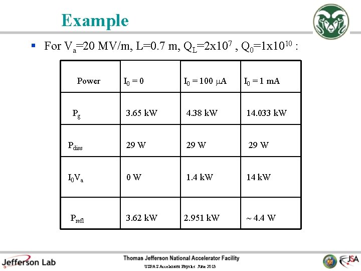
Example § For Va=20 MV/m, L=0. 7 m, QL=2 x 10⁷ , Q 0=1 x 10¹⁰ : I 0 = 0 I 0 = 100 A I 0 = 1 m. A 3. 65 k. W 4. 38 k. W 14. 033 k. W Pdiss 29 W I 0 V a 0 W 1. 4 k. W 14 k. W Prefl 3. 62 k. W 2. 951 k. W ~ 4. 4 W Power Pg USPAS Accelerator Physics June 2013
Off Crest and Off Resonance Operation § Typically electron storage rings operate off crest in order to ensure stability against phase oscillations. § As a consequence, the rf cavities must be detuned off resonance in order to minimize the reflected power and the required generator power. § Longitudinal gymnastics may also impose off crest operation in recirculating linacs. § We write the beam current and the cavity voltage as § The generator power can then be expressed as: USPAS Accelerator Physics June 2013
Off Crest and Off Resonance Operation (cont’d) § Condition for optimum tuning: § Condition for optimum coupling: § Minimum generator power: USPAS Accelerator Physics June 2013
RF Cavity with Beam and Microphonics The detuning is now: USPAS Accelerator Physics June 2013
Qext Optimization under Beam Loading and Microphonics § Beam loading and microphonics require careful optimization of the external Q of cavities. § Derive expressions for the optimum setting of cavity parameters when operating under a) heavy beam loading b) little or no beam loading, as is the case in energy recovery linac cavities and in the presence of microphonics. USPAS Accelerator Physics June 2013
Qext Optimization (cont’d) where f is the total amount of cavity detuning in Hz, including static detuning and microphonics. § Optimization of the generator power with respect to coupling gives: where Itot is the magnitude of the resultant beam current vector in the cavity and tot is the phase of the resultant beam vector with respect to the cavity voltage. USPAS Accelerator Physics June 2013
Qext Optimization (cont’d) where: § To minimize generator power with respect to tuning: USPAS Accelerator Physics June 2013
Qext Optimization (cont’d) § Condition for optimum coupling: and § In the absence of beam (b=0): and USPAS Accelerator Physics June 2013
Homew ork § Assuming no microphonics, plot opt and Pgopt as function of b (beam loading), b=-5 to 5, and explain the results. § How do the results change if microphonics is present? USPAS Accelerator Physics June 2013
Exam ple § ERL Injector and Linac: fm=25 Hz, Q 0=1 x 10¹⁰ , f 0=1300 MHz, I 0=100 m. A, Vc=20 MV/m, L=1. 04 m, Ra/Q 0=1036 ohms per cavity § ERL linac: Resultant beam current, Itot = 0 m. A (energy recovery) and opt=385 QL=2. 6 x 10⁷ Pg = 4 k. W per cavity. § ERL Injector: I 0=100 m. A and opt= 5 x 10⁴ ! QL= 2 x 10⁵ Pg = 2. 08 MW per cavity! Note: I 0 Va = 2. 08 MW optimization is entirely dominated by beam loading. USPAS Accelerator Physics June 2013
RF System Modeling § To include amplitude and phase feedback, nonlinear effects from the klystron and be able to analyze transient response of the system, response to large parameter variations or beam current fluctuations • we developed a model of the cavity and low level controls using SIMULINK, a MATLAB-based program for simulating dynamic systems. § Model describes the beam-cavity interaction, includes a realistic representation of low level controls, klystron characteristics, microphonic noise, Lorentz force detuning and coupling and excitation of mechanical resonances USPAS Accelerator Physics June 2013
RF System Model USPAS Accelerator Physics June 2013
RF Modeling: Simulations vs. Experimental Data Measured and simulated cavity voltage and amplified gradient error signal (GASK) in one of CEBAF’s cavities, when a 65 A, 100 sec beam pulse enters the cavity. USPAS Accelerator Physics June 2013
Conclusi ons § We derived a differential equation that describes to a very good approximation the rf cavity and its interaction with beam. § We derived useful relations among cavity’s parameters and used phasor diagrams to analyze steady-state situations. § We presented formula for the optimization of Qext under beam loading and microphonics. § We showed an example of a Simulink model of the rf control system which can be useful when nonlinearities can not be ignored. USPAS Accelerator Physics June 2013
RF Focussing In any RF cavity that accelerates longitudinally, because of Maxwell Equations there must be additional transverse electromagnetic fields. These fields will act to focus the beam and must be accounted properly in the beam optics, especially in the low energy regions of the accelerator. We will discuss this problem in greater depth in injector lectures. Let A(x, y, z) be the vector potential describing the longitudinal mode (Lorenz gauge) USPAS Accelerator Physics June 2013
For cylindrically symmetrical accelerating mode, functional form can only depend on r and z Maxwell’s Equations give recurrence formulas for succeeding approximations USPAS Accelerator Physics June 2013
Gauge condition satisfied when in the particular case n = 0 Electric field is USPAS Accelerator Physics June 2013
And the potential and vector potential must satisfy So the magnetic field off axis may be expressed directly in terms of the electric field on axis USPAS Accelerator Physics June 2013
And likewise for the radial electric field (see also Explicitly, for the time dependence cos(ωt + δ) USPAS Accelerator Physics June 2013 )
USPAS Accelerator Physics June 2013
USPAS Accelerator Physics June 2013
USPAS Accelerator Physics June 2013
Motion of a particle in this EM field USPAS Accelerator Physics June 2013
The normalized gradient is and the other quantities are calculated with the integral equations USPAS Accelerator Physics June 2013
These equations may be integrated numerically using the cylindrically symmetric CEBAF field model to form the Douglas model of the cavity focussing. In the high energy limit the expressions simplify. USPAS Accelerator Physics June 2013
Transfer Matrix For position-momentum transfer matrix USPAS Accelerator Physics June 2013
Kick Generated by misalignment USPAS Accelerator Physics June 2013
Damping and Antidamping By symmetry, if electron traverses the cavity exactly on axis, there is no transverse deflection of the particle, but there is an energy increase. By conservation of transverse momentum, there must be a decrease of the phase space area. For linacs NEVER use the word “adiabatic” USPAS Accelerator Physics June 2013
Conservation law applied to angles USPAS Accelerator Physics June 2013
Phase space area transformation Therefore, if the beam is accelerating, the phase space area after the cavity is less than that before the cavity and if the beam is decelerating the phase space area is greater than the area before the cavity. The determinate of the transformation carrying the phase space through the cavity has determinate equal to USPAS Accelerator Physics June 2013
By concatenation of the transfer matrices of all the accelerating or decelerating cavities in the recirculated linac, and by the fact that the determinate of the product of two matrices is the product of the determinates, the phase space area at each location in the linac is Same type of argument shows that things like orbit fluctuations are damped/amplified by acceleration/deceleration. USPAS Accelerator Physics June 2013
Transfer Matrix Non-Unimodular USPAS Accelerator Physics June 2013
Stanford Superconducting Accelerator § HEPL at Stanford University was the pioneer laboratory in exploration of srf for accelerator applications. In 1965 they accelerated electrons in a lead-plated resonator § In 1977 HEPL completed first Superconducting Accelerator (SCA) providing 50 MV in 27 m linac at 1. 3 GHz. (a) Single-cell HEPL Nb cavity, resonant frequency 1. 3 GHz (b) HEPL 7 -cell subsection USPAS Accelerator Physics June 2013
MUSL-2 at University of Illinois USPAS Accelerator Physics June 2013
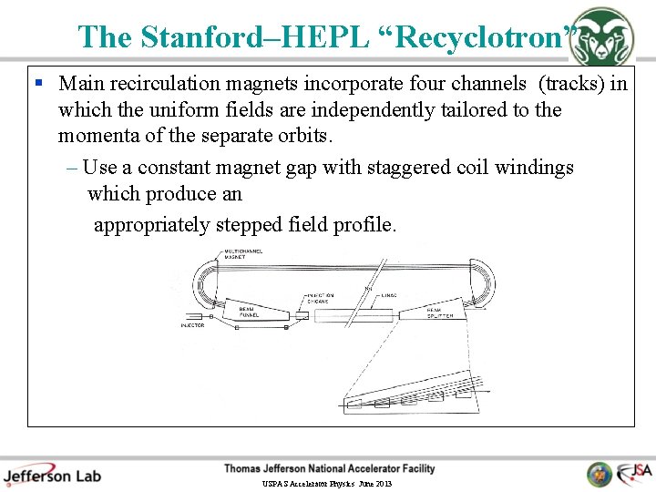
The Stanford–HEPL “Recyclotron” § Main recirculation magnets incorporate four channels (tracks) in which the uniform fields are independently tailored to the momenta of the separate orbits. – Use a constant magnet gap with staggered coil windings which produce an appropriately stepped field profile. USPAS Accelerator Physics June 2013
Beam Energy Recovery in an RF Linac Injector Beam Dump Recirculation path length in standard configuration frontto-back recirculated linac. For energy recovery choose it to be (n + 1/2)λRF. Then USPAS Accelerator Physics June 2013
§ § SCA/FEL Energy Recovery Experiment Same-cell energy recovery was first demonstrated in a superconducting linac at the Stanford SCA/FEL in July 1986 NIMA 259, 1 (1987) Beam was injected at 5 Me. V into a 45 Me. V linac (up to 95 Me. V in 2 passes), 150 A average current (12. 5 p. C per bunch at 11. 8 MHz) The previous “Recyclotron” beam recirculation system could be not used to produce the peak current required for lasing and was replaced by a doubly achromatic single-turn recirculation line. Nearly all the energy was recovered. No FEL inside the recirculation loop. USPAS Accelerator Physics June 2013
Layout of S-DALINAC (Darmstadt) USPAS Accelerator Physics June 2013
S-DALINAC USPAS Accelerator Physics June 2013
S-DALINAC Beam Parameters USPAS Accelerator Physics June 2013
Superconducting 20 -Cell Cavity Material: Niobium (RRR=280) Frequency: 3 GHz Temperature: 2 K Accelerating Field: 5 MV/m Q 0/QL: 3· 109 / 3· 107 Df/Dl: 500 Hz/µm USPAS Accelerator Physics June 2013
§ § The CEBAF at Jefferson Lab “Radical” innovations (had not been done before on the scale of CEBAF): • choice of Superconducting Radio Frequency (SRF) technology • use of multipass beam recirculation Until LEP II came into operation, CEBAF was the world’s largest implementation of SRF technology. USPAS Accelerator Physics June 2013
§ § The CEBAF at Jefferson Lab “Radical” innovations (had not been done before on the scale of CEBAF): • choice of Superconducting Radio Frequency (SRF) technology • use of multipass beam recirculation Until LEP II came into operation, CEBAF was the world’s largest implementation of SRF technology. USPAS Accelerator Physics June 2013
CEBAF Accelerator Layout* *C. W. Leemann, D. R. Douglas, G. A. Krafft, “The Continuous Electron Beam Accelerator Facility: CEBAF at the Jefferson Laboratory”, Annual Reviews of Nuclear and Particle Science, 51, 413 -50 (2001) has a long reference list on the CEBAF accelerator. Many references on Energy Recovered Linacs may be found in a recent ICFA Beam Dynamics Newsletter, #26, Dec. 2001: http: //icfausa/archive/newsletter/icfa_bd_nl_26. pdf USPAS Accelerator Physics June 2013
CEBAF Beam Parameters Beam energy 6 Ge. V Beam current A 100 μA, B 10 -200 n. A, C 100 μA Normalized rms emittance 1 mm mrad Repetition rate 500 MHz/Hall Charge per bunch < 0. 2 p. C Extracted energy spread < 10 -4 Beam sizes (transverse) < 100 microns Beam size (longitudinal) <100 microns (330 fsec) Beam angle spread < 0. 1/γ USPAS Accelerator Physics June 2013
Short Bunches in CEBAF Wang, Krafft, and Sinclair, Phys. Rev. E, 2283 (1998) USPAS Accelerator Physics June 2013
Short Bunch Configuration Kazimi, Sinclair, and Krafft, Proc. 2000 LINAC Conf. , 125 (2000) USPAS Accelerator Physics June 2013
dp/p data: 2 -Week Sample Record Energy Spread less than 50 ppm in Hall C, 100 ppm in Hall A Energy drift X Position => relative energy Drift rms X width => Energy Spread 0. 8 0. 4 Energy spread Secondary Hall (Hall A) 1. 2 X and sigma X in mm Primary Hall (Hall C) 0. 8 Energy drift 0. 4 1 E-4 23 -Mar 27 -Mar 31 -Mar 0 4 -Apr Energy spread 0 23 -Mar Date 27 -Mar 31 -Mar 4 -Apr Time Courtesy: Jean-Claude Denard USPAS Accelerator Physics June 2013
SNS Medium Beta Modules SNS Medium Beta Cavity String: three 6 -cell 805 MHz cavities Pump-out assembly USPAS Accelerator Physics June 2013
Energy Recovered Linacs § The concept of energy recovery first appears in literature by Maury Tigner, as a suggestion for alternate HEP colliders* § There have been several energy recovery experiments to date, the first one in a superconducting linac at the Stanford SCA/FEL** § Same-cell energy recovery with cw beam current up to 10 m. A and energy up to 150 Me. V has been demonstrated at the Jefferson Lab 10 k. W FEL. Energy recovery is used routinely for the operation of the FEL as a user facility USPAS Accelerator Physics June 2013
Jefferson Lab IR DEMO FEL Wiggler assembly Neil, G. R. , et. al, Physical Review Letters, 84, 622 (2000) USPAS Accelerator Physics June 2013
FEL Accelerator Parameters Parameter Designed Measured Kinetic Energy 48 Me. V 48. 0 Me. V Average current 5 m. A 4. 8 m. A Bunch charge 60 p. C Up to 135 p. C Bunch length (rms) <1 ps 0. 4 0. 1 ps Peak current 22 A Up to 60 A Trans. Emittance (rms) <8. 7 mmmr 7. 5 1. 5 mmmr Long. Emittance (rms) 33 ke. Vdeg 26 7 ke. Vdeg Pulse repetition frequency (PRF) 18. 7 MHz, x 2 18. 7 MHz, x 0. 25, x 0. 5, x 2, and x 4 USPAS Accelerator Physics June 2013
FEL Accelerator Parameters Parameter Designed Measured Kinetic Energy 48 Me. V 48. 0 Me. V Average current 5 m. A 4. 8 m. A Bunch charge 60 p. C Up to 135 p. C Bunch length (rms) <1 ps 0. 4 0. 1 ps Peak current 22 A Up to 60 A Trans. Emittance (rms) <8. 7 mmmr 7. 5 1. 5 mmmr Long. Emittance (rms) 33 ke. Vdeg 26 7 ke. Vdeg Pulse repetition frequency (PRF) 18. 7 MHz, x 2 18. 7 MHz, x 0. 25, x 0. 5, x 2, and x 4 USPAS Accelerator Physics June 2013
ENERGY RECOVERY WORKS Gradient modulator drive signal in a linac cavity measured without energy recovery (signal level around 2 V) and with energy recovery (signal level around 0). Courtesy: Lia Merminga USPAS Accelerator Physics June 2013
Longitudinal Phase Space Manipulations Simulation calculations of longitudinal dynamics of JLAB FEL Piot, Douglas, and Krafft, Phys. Rev. ST-AB, 6, 0030702 (2003) USPAS Accelerator Physics June 2013
Phase Transfer Function Measurements Krafft, G. A. , et. al, ERL 2005 Workshop Proc. in NIMA USPAS Accelerator Physics June 2013
Longitudinal Nonlinearities Corrected by Sextupoles Off Nominal Settings Basic Idea is to use sextupoles to get T 566 in the bending arc to compensate any curvature in the phase space. USPAS Accelerator Physics June 2013
IR FEL Upgrade USPAS Accelerator Physics June 2013
IR FEL 10 k. W Upgrade Parameters Parameter Design Value Kinetic Energy 160 Me. V Average Current 10 m. A Bunch Charge 135 p. C Bunch Length <300 fsec 10 mm mrad Transverse Emittance Longitudinal Emittance Repetition Rate USPAS Accelerator Physics June 2013 30 ke. V deg 75 MHz
USPAS Accelerator Physics June 2013
USPAS Accelerator Physics June 2013
ILC (TESLA) 9 -Cell Cavity USPAS Accelerator Physics June 2013
ILC Superconducting Linac USPAS Accelerator Physics June 2013
USPAS Accelerator Physics June 2013
ERL X-ray Source Conceptual Layout USPAS Accelerator Physics June 2013 CHESS / LEPP
Bend Undulater Wiggler e– e– white source Flux [ph/s/0. 1%bw] Brightness [ph/s/mm 2/mr 2/0. 1%bw] e– partially coherent source USPAS Accelerator Physics June 2013 powerful white source
Why ERLs for X-rays? CHESS / LEPP ESRF 6 Ge. V @ 200 m. A ERL 5 Ge. V @ 10 -100 m. A εx = 4 nm mrad εy = 0. 02 nm mrad B ~ 1020 ph/s/mm 2/mrad 2/0. 1%BW LID = 5 m εx = εy 0. 01 nm mrad B ~ 1023 ph/s/mm 2/mrad 2/0. 1%BW LID = 25 m ERL (no compression) ESRF ERL (w/ compression) t USPAS Accelerator Physics June 2013
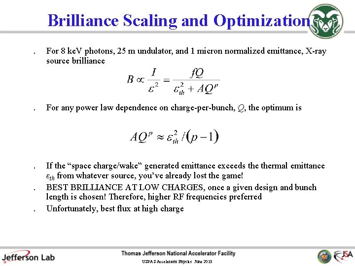
Brilliance Scaling and Optimization. For 8 ke. V photons, 25 m undulator, and 1 micron normalized emittance, X-ray source brilliance . For any power law dependence on charge-per-bunch, Q, the optimum is . If the “space charge/wake” generated emittance exceeds thermal emittance εth from whatever source, you’ve already lost the game! BEST BRILLIANCE AT LOW CHARGES, once a given design and bunch length is chosen! Therefore, higher RF frequencies preferred Unfortunately, best flux at high charge . . USPAS Accelerator Physics June 2013
ERL Phase II Sample Parameters Parameter Beam Energy Average Current Fundamental frequency Charge per bunch Injection Energy Normalized emittance Energy spread Bunch length in IDs Total radiated power Value 5 -7 100 / 10 1. 3 77 / 8 10 2 / 0. 2* 0. 02 -0. 3* 0. 1 -2* 400 * rms values USPAS Accelerator Physics June 2013 CHESS / LEPP Unit Ge. V m. A GHz p. C Me. V μm % ps k. W
ERL X-ray Source Average Brilliance and Flux CHESS / LEPP Courtesy: Qun Shen, CHESS Technical Memo 01 -002, Cornell University USPAS Accelerator Physics June 2013
ERL Peak Brilliance and Ultra-Short Pulses CHESS / LEPP Courtesy: Q. Shen, I. Bazarov USPAS Accelerator Physics June 2013
e. RHIC USPAS Accelerator Physics June 2013
Coherent Synchrotron Radiation • Coherent synchrotron radiation (CSR) is electromagnetic energy radiated from the “bunch-as-a-whole” at wavelengths longer than the bunch length. • The radiation from the individual electrons occurs at the same phase. Coherent superposition increases the output power level. Goes as bunch charge squared. Not unique to synchrotron radiation (e. g. , transition and undulator radiations) • Nodvick and Saxon (in more modern notation) • First observed in electron linacs (Nakazato, et al. ) USPAS Accelerator Physics June 2013
Compact THz Source Injector Superconducting Cavity Beam Dump THz Radiation Undulator U. S. Patent 6, 753, 662 assigned to Jefferson Lab USPAS Accelerator Physics June 2013
SRF photoinjectors § High CW RF fields possible § Significant R&D required Rossendorf proof of principle experiment: 1. 3 GHz, 10 Me. V 77 p. C at 13 MHz and 1 n. C at < 1 MHz BNL/AES/JLAB development: 1. 3 GHz ½-cell Nb cavity at 2 K Test diamond amplified cathode AES/BNL development: 703. 75 MHz ½-cell Nb photoinjector USPAS Accelerator Physics June 2013
Source Parameters USPAS Accelerator Physics June 2013
USPAS Accelerator Physics June 2013
USPAS Accelerator Physics June 2013
USPAS Accelerator Physics June 2013