The University of Jordan Mechatronics Engineering Department Chapter
 Dr. Osama")

 � It is a form of programmable automation in which the")
 � NC is used for machine tool applications, such as drilling,")

 Program Machine Control Unit MCU Computer Processing Equipment (cutting tool)")

 : � It is a microcomputer and control hardware.")


: Absolute Positions are defined Relative to the")

: It is an NC system whose MCU is")
 �Fixed cycles and programming subroutines :")
 �Cutter length and size compensation: such")
 � Communications interface: linking with other")

 1 -")

 Main memory (primary storage)")
 Secondary memory (high – capacity secondary memory, auxiliary storage, or secondary")


 and the MCU: PC’s are used for CNC in two")

 1 - Operating system: § It")
 2 - Machine Interface: Used to operate")
: � A central computer is connected to multiple")
 Two ways of DNC: � Switching network. � Local area")
 Cons = limited number of machines can be")
 Hierarchy Central (host) computer")


")


. V: Cutting speed (m/min) or ft/min.")

 Depth of cut: The distance the tool penetrates below")


: Used to inspect dimensions of")
 1")


 The table moves a distance equal to")
: no verification")
 are involved")


 How many pulses required")
 A : angle of lead screw")
")


 CR 2 : Computer control")


 consists of two numerical digits (following “G”")


 APT : Automatically")


 Computer Tasks (Done next) : (after programmer’s job) 1. Input translation : result")


 ,")


 � The machine operator performs the part")
 � Simultaneous machining while the next program is being written")
- Slides: 115
The University of Jordan Mechatronics Engineering Department Chapter 7 Numerical Control (NC) Dr. Osama Al-Habahbeh 2015
Example CNC Products �Car engine �Gears �Woodworking, furniture �Metal parts such as fittings, brackets, screws, flanges �Artifacts �Plastic parts �And many more
Numerical Control (NC) � It is a form of programmable automation in which the machine tool is controlled by a program ( program of instructions). � The program represents relative positions between a work head (e. g. , cutting tool) and a work part (the object being processed). � NC is good for low and medium production because of the capability to change the program (between
Numerical Control (NC) � NC is used for machine tool applications, such as drilling, milling, turning, …. . In addition to assembly drafting & inspection. � Work head movement is controlled relative to the work part. � The first NC machine was developed in 1952 by a group of American inventors.
7. 1 Fundamentals of NC Technology 7. 1. 1 Basic Components of an NC System � The Basic Components of an NC System : 1. Program of instructions 2. Machine control unit 3. Processing equipment
Numerical Control (NC) Program Machine Control Unit MCU Computer Processing Equipment (cutting tool)
1. Part Program of Instructions: � It is the set of details step-by-step commands that direct the actions of the processing equipment. � “Part Programmer” is the name of the person who prepares the program. � The commands refer to positions of a cutting tool relative to the work part. � Other program instructions include spindle speed, feed rate, etc. The program is coded electronically, or using diskettes. � Older technologies include magnetic tape and punched tape.
2. Machine Control Unit (MCU) : � It is a microcomputer and control hardware. The hardware includes interface components with the processing equipment and feedback control elements. � The MCU also includes reading devices to enter the program into memory. � MCU installed software include: Ø Control system software Ø Calculations algorithms Ø Translations software, to convert the NC part program into a usable format for the MCU. � NC includes hard-wired electronics and CNC.
3. Processing Equipment : � It performs the actual productive work (e. g. , machining ) � Its operation is directed by program of instructions through the MCU. � In machining , the processing equipment consists of the worktable and spindle , as well as the motors and controls to drive them.
7. 1. 2 NC Coordinate Systems : � A part programmer must define a standard axis system to specify the position of the work head. � There are two axis systems used in NC : 1. Flat & prismatic workparts system. 2. Rotational parts system. � Both are based on Cartesian coordinate system.
1 - System for flat & prismatic workparts : � It consists of (x, y, z) plus three rotational axes (a, b, c) as shown below :
System for flat & prismatic workparts : � Generally , if the machine has four or five axes , three of them will be linear (x, y, z) and one or two will be rotational axes. � Most NC machine systems have less than six axes.
2. Rotational NC System : Y-axis is not used! Radial location of the tool Longitudinal axis ( parallel to the rotation axis )
Rotational NC System : � The origin of the coordinate axis system is located based on convenience , e. g. , the corner of the part. � The tool must be positioned at the target point ( Location on the worktable ) , where the axis system origin ( location in the workpart ) is known relative to the target point.
7. 1. 3 Motion Control Systems : � Some NC processes are performed at discrete locations on the workpart (e. g. , drilling , spot wedding ) � Other NC process are performed while the workhead is moving ( e. g. turning , milling , …) � Types of movement : Straight line , circular , curvilinear path , …
Features of motion Control systems Point-to-Point Versus Continuous Path Control : 1 -Point-to-Point Systems ( positioning Systems ) : � No regard to the path→ Just a series of point locations at which operations are performed.
2. Continuous Path Systems : � The tool trajectory relative to the workpart is controlled → Perform the process while moving.
Fundamentals of NC technology Motion Control Systems Continuous path systems : (continuous path systems ) (Straight – cut NC ) Tool moves parallel to one axis “only“ (Contouring) Tool moves relative to two or more axes (simultaneous control)
Interpolation Methods � The smaller the line segments the better the accuracy → small tolerance . � It is an important aspect of contouring. • Tolerance : Inside , Outside , Inside & Outside.
Inside Tolerance
Outside Tolerance
Inside & Outside
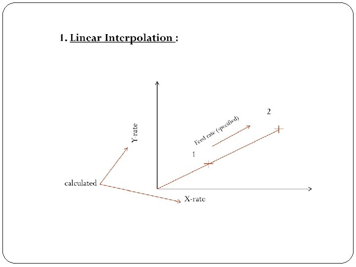
NC Interpolation methods for continuous path Control : 1. Linear Interpolation : • Used when a straight line path is to be generated. • 2 - axis & 3 -axis linear interpolations are used. • The programmer specifies the beginning and end points of the straight line , and feed rate along the straight line.
2. Circular Interpolation: It permits programming of a circular arc. The following parameters are needed : Starting & End points. 2. Center or radius of the arc. 3. Cutter direction ( along the arc ) 1.
2. Circular Interpolation:
3. Helical Interpolation : � It combines circular & linear interpolation.
3. Helical Interpolation :
4. Parabolic & Cubic Interpolation : � Most applications in aerospace & automotive industries. � They use higher–order eqns. & require higher computational power. � They are less common→ complex.
Absolute versus incremental positioning (of work head): Absolute Positions are defined Relative to the origin of the coordinate System (axis system) [x=40, y=50] Incremental Positions are defined relative to the previous location of the tool (or next position relative to the present) [X=20, y=30]
Absolute versus incremental positioning
7. 2 Computer Numerical Control (CNC): It is an NC system whose MCU is based on a PC rather than on a hard – wired controller. 7. 2. 1 Features of CNC: • Storage of more than one part program. • Various forms of program inputs; such as floppy disks and manual data entry. • Program editing at the machine tool; the program can be connected and optimized Locally.
7. 2. 1 Features of CNC (CONT. ) �Fixed cycles and programming subroutines : such as macros that can be called within the program. �Interpolation: usually executed by a stored program algorithm. �Positioning features for setup : such as “ position set” (software option) that helps in setting up the machine tool for a given work part.
7. 2. 1 Features of CNC (CONT. ) �Cutter length and size compensation: such as using a tool length sensor built into the machine. The tool path is then corrected accordingly (tool profile) (tool path page 48 ) �Acceleration and deceleration calculations: to prevent tool marks on the work surface during fast turns (slow down at turns).
7. 2. 1 Features of CNC (CONT. ) � Communications interface: linking with other devices is useful for downloading programs, collecting operational data, and interfacing with robots to load and unload parts. � Diagnostics: of malfunctions and breakdowns.
7. 2. 2 The Machine Control Unit for CNC � The MCU consists of : 1. Central processing unit (CPU) 2. Memory 3. I/O interface 4. Controls for machine tool axes and spindle speed 5. Sequence controls for other functions These subsystems are interconnected by a system bus.
7. 2. 2 The machine control unit for CNC (CONT. ) 1 - Central Processing Unit (CPU): It is the brain of the MCU it is divided into three sections: i. Control section: It retrieves commands from memory and generates signals to activate other components. ii. Arithmetic –logic unit (ALU): It consists of the circuitry to perform calculations. iii. Immediate access memory: It provides a temporary storage for data
2 -Memory: It is used to store the software and data needed to operate the CNC system.
Memory � CNC memory is divided into two categories: a) Main memory (primary storage) : Consists of ROM (read only memory) and RAM (random access memory). Ø ROM is used to store operating system and interface programs. Ø RAM is used to store NC part programs (change with jobs).
CNC memory b) Secondary memory (high – capacity secondary memory, auxiliary storage, or secondary storage): Used to store large programs and data files, which are transferred to main memory as needed. Example: Hard disks
3 -Input/Output interface: • It provides communication between the components of the CNC system, other systems, and the operator (through the operator control panel) Used to control speeds, feed, …. . • It also includes a display (CRT or LED) to indicate current status of the program. • I/O interface also include manual program entry capability in addition to program transmission via LAN.
4 - Controls for machine tool axes and spindle speed: These are hardware components that control the position and velocity (feed rate) of each axis, as well as the spindle speed. The spindle is used to drive either: (a) The work piece -> like turning (b) A rotating cutter -> like milling & drilling
5 - Sequence controls for other machine tool functions: � Other control functions include ON/OFF (binary) actuations, interlocks [coolant control, tool changer, wearing, part loading] � To manage these auxiliary functions (instead of the CPU).
Personal computers (PC’s) and the MCU: PC’s are used for CNC in two configurations: a) The PC is used for CNC as a front-end interface for the MCU b) The PC contains the motion control board required to operate the machine tool
7. 2. 3 CNC Software There are three types of software used in CNC systems: 1. Operating system 2. Machine interface 3. Application
7. 2. 3 CNC Software (CONT. ) 1 - Operating system: § It consists of: 1 - An editor: which permits the operator to input and edit NC part programs. 2 - A control program: decodes the part program instructions performs calculations. 3 - An executive program: manage the execution of the CNC
7. 2. 3 CNC Software (CONT. ) 2 - Machine Interface: Used to operate the communication link between the CPU and the machine tool 3 - Application software: Consists of the NC part programs that are written for machining. Some CNC auxiliary functions such as coolant control, fixture clamping and counters are often implemented by a PLC in the MCU.
7. 3 Distributed Numerical Controls (DNC): � A central computer is connected to multiple MCU’s. complete part programs are sent from the central computer to the machine tools (via MCUs ). � Data can be downloaded from the central computer to machine tools such as part programs, list of tools needed for job, and setup instructions. � Data can be uploaded from the machine tools to the central computer such as piece counts, actual machining times, and
Distributed Numerical Controls (DNC) Two ways of DNC: � Switching network. � Local area network (LAN).
Switching network (Using RS-232 -c connection) Cons = limited number of machines can be connected.
Local Area Network (LAN) Hierarchy Central (host) computer
7. 4 Applications of NC Two categories: � 1. Machine tool applications: Usually associated with the metalworking industry. 2. Non- Machine tool applications: Other industries.
7. 4. 1 Machine Tool Applications Machining operations and NC machine tools: Four types of machining operations: � � 1. Turning. 2. Drilling. 3. Milling. 4. Grinding. Speed, feed, depth of cut are called “cutting conditions”.
Turning (on a Lathe)
Drilling
Peripheral Milling
Surface grinding
Controller parameters Where: N: Spindle rotation speed (RPM). V: Cutting speed (m/min) or ft/min. D: Milling cutter diameter (m, ft).
Controller parameters In milling, “chip load or feed” means the size of the chip formed by each tooth in the cutter. Where: : Feed rate (mm/min, in/min). : Rotational speed (RPM). : Number of teeth on the milling cutter. : Feed (mm/tooth, in/tooth).
For Tuning Operation (mm/revolutio n) Depth of cut: The distance the tool penetrates below the original surface of the workpart (mm, in).
Common NC machine tools i. NC lathe: � Either horizontal or vertical axis. � Requires two-axis. � Continuous path control. � Straight turning produces a straight cylindrical geometry. � Contour turning creates a profile.
Common NC machine tools ii. NC boring mill: � Horizontal and vertical spindle. � Boring is similar to turning, except that an internal cylinder is created instead of an external cylinder. � Continuous path. � Two-axis control.
Common NC machine tools iii. NC drill press: � Point-to-point control of the workhead (spindle containing the drill bit). � Two-axis (x - y) control of the worktable. iv. NC milling machine: � Continuous path control. � Straight cut and contouring operations. v. NC cylindrical grinder: � It is similar to a turning machine, except that the tool is a grinding wheel.
Common NC machine tools � Machining center : A machine tool capable of performing multiple machining operations on a single work piece in one setup.
NC application characteristics. � Part characteristics most suited to NC : 1. 2. 3. 4. 5. 6. Batch production. Repeat orders. Complex part geometry. Much metal needs to be removed from the work part. Many separate machining operations on the part. The part is expensive. � NC for other metalworking processes : § Punch press for sheet metal hole punching. § Press for sheet metal bending. § Welding machines : spot welding and continuous arc welding . § Thermal cutting a machines such as laser cutting and plasma arc cutting. § Tube bending machines.
7. 4. 2 Other NC Applications: 1 - Electrical wire wrap machines : Used to establish connections between components on wiring boards in electronics. 2 - Components insertion machines: Used in mechanical assembly and for inserting electronic components into printed circuit boards. 3 - Drafting machines: Used in CAD systems, such as high–speed X-Y plotter
Other NC Applications 4 - Coordinate measuring machines (CMM): Used to inspect dimensions of a part (automatically). 5 - Tape-laying machines for polymer composites : The workhead is a dispenser of a matrix composites tape. The machine is programmed to lay the tape onto a mold. 6 - Filament winding machines for polymer composites : Similar to the preceding machine except that a filament is dipped in uncured polymer and wrapped around a rotating Pattern of cylindrical shape.
7. 4. 3 Advantages & disadvantage of NC �Advantages of NC: (over manual) 1 - Nonproductive time is reduced: fewer setups, Less setup time … 2 - Greater accuracy and repeatability: reduces variations due to operator skill differences, fatigue. . . 3 - Lower scrap rates: due to higher accuracy. 4 - Inspection requirements are reduced: parts are virtually identical.
Advantages of NC 6 - Engineering changes can be accommodated more gracefully (using part program). 7 - Simple fixtures (supporting devices) are needed NC takes care of positioning. 8 - Shorter manufacturing lead times. Lead time: elapsed time between order and completion. 9 - Reduced parts inventory: due to fewer setups and easier changeovers. 10 - Less floor space required: NC is more efficient less NC machines are needed. 11 - Operator skill-level requirements are reduced: tending an NC machine involves loading, unloading & changing tools (only).
�Disadvantages of NC : 1 - Higher investment cost. 2 - Higher maintenance effort. 3 - Part programming. 4 - Higher utilization of NC equipment: It is done to justify the cost, however, it takes more shifts and personnel cost.
7. 5 Engineering Analysis of NC Positioning Systems �An NC positioning system converts the coordinates in the part program into positions of the tool. Simple positioning system
Simple position system Screw pitch p(mm/thread, in/thread) The table moves a distance equal to the pitch for each
�Types of position control system: A. Open loop (as shown above ): no verification of actual position. B. Closed loop: confirms that the actual position is the desired one (in the program).
Closed loop: - Closed-loop is used when high resisting forces (of machining) are involved (such as in milling or turning).
7. 5. 1 open-loop positioning systems � Typically uses a stepper motor, driven by pulses, generated by MCU. Each pulse rotates the motor through a "step angle” (in degree) α : Step angle in degree. : Number of step angles for the motor. : Angle through which the motor rotates (degrees). : Number of pulses received by the motor. : Step angle (degree/pulse).
7. 5. 1 Open-loop positioning systems The motor shaft is generally connected to the lead screw through a gearbox, so: Where : angle of lead screw rotation (degrees). : Gear ratio. : Rotational speed of motor (rpm). N : Rotational speed of lead screw (rpm).
7. 5. 1 Open-loop positioning systems Linear movement of work table is given by: : X-axis position relative to the starting position (mm, in). : Pitch of lead screw (mm/rev, in/rev). : Number of lead screw revolutions. The number of pulses required to achieve a specified xposition increment is given by (using the preceding relationships):
7. 5. 1 Open-loop positioning systems Control pulses are generated at a certain frequency, which drives the worktable, where: : Rotational speed of lead screw (rpm). : Pulses train frequency ( Hz, pulses/s). : Steps per revolution or pulses per revolution. : Gear ratio.
7. 5. 1 Open-loop positioning systems The work table travel speed in the direction of lead screw axis is: : (mm/min, in /min) : Table feed rate (mm/min, in /min). : lead screw pitch (mm/rev, in/rev).
7. 5. 1 open-loop positioning systems �The required pulse train frequency to drive the table at a given rate is :
Ex. 7. 1 : NC Open-Loop Positioning � The work table of a positioning system is driven by a lead screw whose pitch = 6 mm. The lead screw is connected to the output shaft of a stepper motor though a gearbox whose ratio is 5 : 1 Motor lead screw The stepper motor has 48 step angles. The table must move a distance of 250 mm at a linear velocity = 500 mm/min.
7. 5. 1 Open-loop positioning systems • Determine : a) How many pulses required to move the table the specified distance ? b) The required motor speed and pulse rate to achieve the desired table velocity ?
7. 5. 1 Open-loop positioning systems Solution: a) A : angle of lead screw rotations.
7. 5. 1 Open-loop positioning systems b)
7. 5. 2 Closed-Loop Positioning Systems � They use servomotors and feedback measurements to ensure that the worktable is moved to the desired position. � A common feedback sensor is the optical encoder :
7. 5. 2 Closed-Loop Positioning Systems � An optical encoder is a device for measuring rotational speed. � The equations that define the operation of a closed-loop NC positioning system one similar to those for an open-loop system. In the optical encoder , the angle between slots in the disk is: α : (deg/slot) ns : number of slots in disk np : # of pulses sensed by the encoder &emitted
7. 5. 2 Closed-Loop Positioning Systems x : worktable pos. p : lead screw pitch(mm/rev) vt : worktable velocity (mm/min) fr : feederate (mm/min) fp : frequency of the pulse train (Hz, pulse / sec ) The pulse train generated by the encoder is compared with position and feed rate specified in the part program , and the difference is used by the MCU to drive a servomotor , which drives the worktable. Closed-loop NC is good for milling and turning because of the
7. 5. 3 Precision in NC Positioning � NC positioning system has three measures of precision : 1. Control resolution 2. Accuracy 3. Repeatability Worstcase scenario Gear back lash, deflection, etc. . (distinguishable points) By the MCU
Precision in NC Positioning CR 1 : Electromechanical (mm) CR 2 : Computer control system (mm) L : Axis range (mm) B : Number of bits in the devoted bit storage register Both equations can be used for open or closed loop. * Typical value of CR is 0. 0025 mm Standarddeviation
7. 6 NC Part Programming �Consists of planning and documenting the sequence of processing steps to be performed on an NC machine. �Methods of part programming : 1. Manual part programming. 2. Computer-assisted part programming. 3. Part programming using CAD/CAM. 4. Manual data input.
7. 6. 1 Manual Part Programming � The programmer prepares the NC code using a low- level machine language, which is based on binary numbers. This language is understood by the MCU. � NC uses a combination of binary and decimal number systems . Called the “binary-coded decimal (BCD) system” , for example , the decimal value 1250 is coded in BCD as in the following table.
Manual Part Programming Number Binary number Decimal value 1 st 0001 1000 2 nd 0010 200 3 rd 0101 50 4 th 0000 0 sequence Sum 1250
Binary & decimal number conversion Binary Decimal 0000 0 0101 5 0001 1 0110 6 0010 2 0111 7 0011 3 1000 8 0100 4 1001 9
Manual Part Programming • In addition to numerical values, the NC coding system provides for alphabetical characteristics and other symbols. A “word” specifies a detail about the operation , such as x-position , y-position , feed rate and spindle speed. • A “block” is one complete NC instruction , it specifies the destination for the move , speed and feed. • “Block format” or (tape format) is the organization of “words” within a block. • Modern Controllers use the word address format which uses a letter prefix and spaces to separate words , order of
Drilling Example : � The two commands to perform the two drilling operations are : 1. N 001 G 00 X 07000 Y 03000 M 03 2. N 002 Y 06000 � Where : N : sequence # prefix X : x-axis prefix Y : y-axis prefix G-words are preparatory words
Manual Part Programming • G-words (or G-codes) consists of two numerical digits (following “G” prefix ). • For example , G 00 prepares the controller for a point-to- point rapid traverse move between the previous point and the endpoint defined in the current command. • M-words are used to specify miscellaneous auxiliary functions available on the machine tool. • The M 03 in the example is used to start the spindle rotation.
Manual Part Programming � The words in a block are usually given in the following order: Ø Sequence number (N-Word) Ø Preparatory word (G-word) Ø Coordinates (x- , y- , z- words for linear axis A- , B- , C- words for rotational axes) Ø Feed rate (F-word) Ø Spindle speed (S-word) Ø Tool Selection (T-word) Ø Miscellaneous command (M-word)
Manual Part Programming � See Appendix A 7 for the details of the coding system in manual part Program. � Manual part programming is used for point-to-point as well as contouring jobs such as milling and turning . However , for computer 3 -D machining operations, computer-assisted part programming is used.
7. 6. 2 Computer-Assisted Part Programming � Manual part programming can be tedious. However, in computer-assisted programming, the tasks are divided between the programmer and the computer : 1) The Part Programmers Job (Done 1 st) � The machining instructions are written in English-like statements that are subsequently translated by the computer into low-level machine code. � The two main tasks for the programmer are : 1. Define the geometry of the part. 2. Specify the tool path and operation sequence.
Computer-Assisted Part Programming Example : Geometry Elements : 1. Points 2. Lines 3. Circles
Computer-Assisted Part Programming Ex. Cont. : (High level language /general purpose) APT : Automatically programmed tooling
Computer-Assisted Part Programming Ex. Cont. : 1 - Define the geometry : P 4=point/35, 90, 0 points x , y , z coordinates L 1=Line/P 1 , P 2 C 1 = Circle/Center , P 8 , Radius , 30. Circle center of circle location circle radius
Computer-Assisted Part Programming 2 - Total path & sequence : � Outline contouring : if cutting tool at P 2 (along L 1), to cut along L 2 : GOLFT/L 2 , TANTO , C 1 Turn left onto L 2 Tangent to Circle � Continuous path motion command � EX : GOTO/PS (move the tool to point 5 ) � Cutting Speed & feed rates must be also specified.
(2) Computer Tasks (Done next) : (after programmer’s job) 1. Input translation : result in an output file called PROFIL. 2. Arithmetic & Cutter offset computations : result in an output file called CLFILE (Cutter location file) 3. Editing : output file called CLDATA (Machine Commands), it depends on the type of the machine tool (low-level code) for the controller of the machine tool. 4. Post-processing : a separate computer program. (specific to the concerned tool) • O/P of post processing is a G-codes program in addition to x , y , z coordinates , S , F , M word address format. • Post processing is an interface between APT & the machine tool.
7. 6. 3 NC Part Programming Using CAD/CAM � A CAD/CAM System is a computer graphics system that integrates design and manufacturing functions. It can perform NC part programming. � In this method , the computer does most of the part programmer’s Job.
Advantages: 1. Part program can be simulated off-line on the CAD/CAM system to verify its accuracy. 2. Time & cost of the operation can be determined by the CAD/CAM system. 3. Automatic tool selection. 4. Automatic optimization of speeds & feeds for work material & operations. 5. Immediate visual verification of geometric elements.
Geometry definition using CAD/CAM : � A computer graphics model of each part is developed by the designer . The model contains geometric , dimensional and material specifications for the part. • The model is stored in a database, in order to perform NC operations, the programmer retrieves the part geometry model from storage , and uses that model to construct the cutter (Tool) path. Where the geometry is already defined.
Geometry definition using CAD/CAM : • Geometric elements are then labeled (with symbols) , e. g. : lines(L 1, L 2) , circles(CI, C 2) , etc …. • Sometimes , they are already labeled. • Points are defined in a coordinate system using the computer graphics system. • Lines & circles are defined from the points.
7. 6. 3 Tool path generation using CAD/CAM � Most CAD/CAM systems have tool libraries that can be called by the programmer. � The programmer decides which tool is appropriate for the operation at hand. Then he/she specifies it for the tool path , this permits the tool diameter to be entered automatically for tool offset calculations. � New tools can be added to the library as needed.
Tool path generation using CAD/CAM � Tool path can be defined using the interactive graphics system by entering the motion commands one-by-one. � Individual statements in APT are entered , and the CAD/CAM system provides immediate graphics display of the action resulting from the command. � A more advanced approach for generating tool path commands is to use an automatic software module, which is a subroutine that executes the machines cycle provided that it is given the required parameters. � An animated simulation can be provided for validation purposes.
Computer – Automated part programming : � It is a futuristic fully automated NC part programming procedure. � Given the geometric model of the part, the system could accomplish NC part programming without human assistance. � Example of machining cycles available in automatic programming modules include facing , shoulder facing
Facing and shoulder facing :
Mastercam : � It is the leading commercial CAD/CAM software package for CNC part Programming. � Files from other CAD packages can be translated for use within Master cam as well. � The input includes the part geometry , work piece orientation & material , type of operation (e. g. milling ) , cutting tool, cutting parameters (e. g. hole depth ) , & matching post process for the machine tool. � The output would be a word address format program.
7. 6. 4 Manual Data Input (MDI) � The machine operator performs the part programming task at the machine tool . The programmer manually enters the part geometry data and motion commands directly into the MCU. � MDI is AKA conversational programming. It requires minimal initial investment , but it is more prone to errors . It typically includes a monitor & keyboard. � Entering commands can be done using a menu – driven procedure→ that is responding to a series of questions.
Manual Data Input (MDI) � Simultaneous machining while the next program is being written is a desired feature of MDI systems. � See Appendix A 7 & B 7 for more details & examples on coding for manual part programming & part programming with APT .