Components of Image Quality Radiographic Artifacts Radiologic Technology


")

 = one thousandth of an ampere. n The")


 – Responsible for dark areas n Scatter")
")


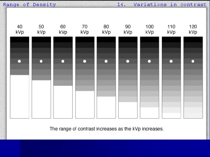


 n Increases as:")
 on scatter")


 & cassette")


 to image")


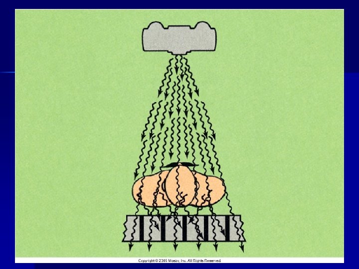
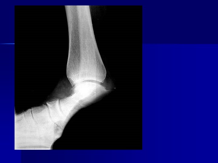
 n PART FAR FROM THE CASSETTE")


- Slides: 160
Components of Image Quality & Radiographic Artifacts Radiologic Technology A Spring 2010 Final
n X-ray Exposure Factors n Radiographic Density & Contrast n Components of Image Quality n Radiographic Artifacts
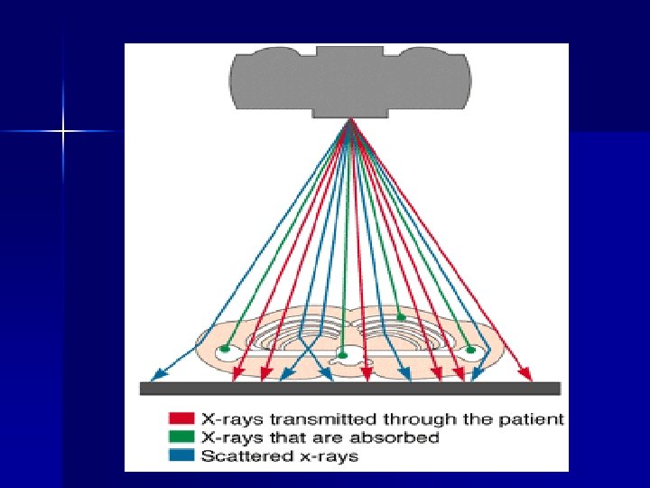
Review Chapter 7 n Primary radiation exits the tube n Interacts with various densities in the body n Photons may be absorbed n Scattered n Passed through without any interference to the cassette or image receptor (IR)
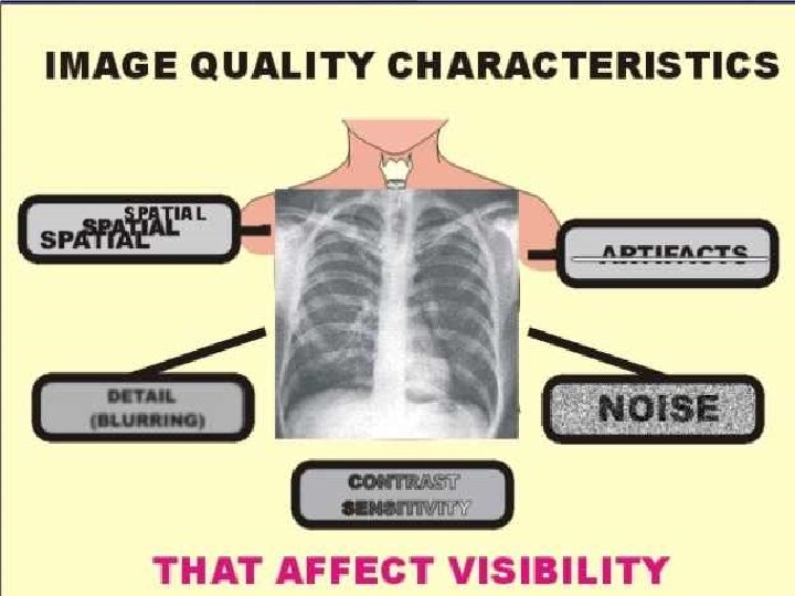
How well we can see something on the image
Image detail is affected by:
Photographic Properties 1 2
X-ray Exposure Factors TECHNIQUE SELECTION: n Radiographer selects the n Kilovoltage peak (k. Vp) n Milliamperage (m. A) & time (s) n Milliamperage x time = m. As (milliamperage multiplied by a set time measured in seconds) n
Kilovoltage Peak n k. Vp n One kilovolt = 1000 volts n The amount of voltage selected for the x-ray tube. n Range n k. Vp 30 to 150 k. Vp controls _____ ?
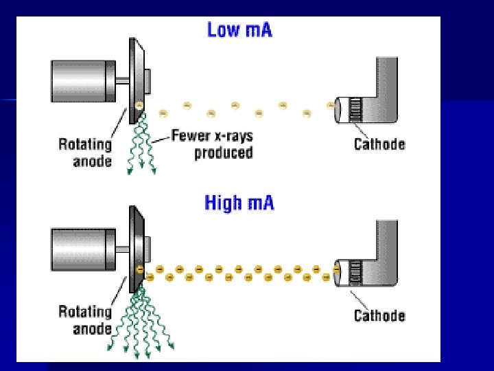
Milliamperage n One milliampere (m. A) = one thousandth of an ampere. n The amount of current supplied to the xray tube n How many x-rays will be produced n Range 10 to 1200 m. A
Time n In seconds n How long x-rays will be produced n 0. 001 to 6 seconds
Milliampere Seconds n Technologists think in terms of m. As n Calculated by m. A x seconds n Ex: 100 m. A X 0. 2 s = 20 m. As n How many x-rays will be produced and for how long. n Modern x-ray machines only allow control of n m. As controls ________ ?
Factors Affecting Density n Primary control factor: n Influencing factors:
Primary Controlling Factor of Density 1. m. As 2. m. A = AMOUNT of electrons sent across the tube combined with TIME (S) = m. As 3. m. As controls DENSITY on radiograph primary function of m. As is DENSITY
Imagine this… n If the m. A station is changed from 200 to 400 m. A, twice as many electrons will flow from the cathode to the anode. n From 10 m. A to 1000 m. A = 100 x more n m. A controls how many electrons are coming at the target n m. As is a combination of how many and for how long (seconds)
10 m. A 1000 m. A
Changing Mas – Changes Density + 25 % + 50 % mas
Influencing Factor on Density:
k. Vp more energy = more photons passing though tissue & striking the image ______ = doubling of exposure to the film _______ = halving of exposure to the film á _____ rule will also change the contrast of the image because k. V is the primary method of changing image contrast. Remember : ___ change ( ) KVP has the same effect as doubling or ½ the MAS on density
Change in k. Vp controls the energy level of the electrons and subsequently the energy of the x-ray photons. n A change from 72 k. Vp will produce x-rays with a lower energy than at 82 k. Vp n Difference between a ball traveling 72 mph and 82 mph (how much energy did it take to throw the ball at the rates? )
+ 15% kvp - 15% kvp
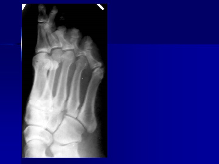
Radiolucent vs. Radiopaque n ______ materials allow x-ray photons to pass through easily (soft tissue). n _____ materials are not easily penetrated by xrays (bones)
Creating the Image n Transmission (no interaction) – Responsible for dark areas n Scatter (grays) – produces no diagnostic info n Absorption (photoelectric effect) – Responsible for light areas
Images n ______ = THE AMOUNT OF BLACKENING “DARKNESS” ON THE RADIOGRAPH (m. As) n ______ – THE DIFFERENCES BETWEEN THE BLACKS TO THE WHITES (k. Vp)
Why you see what you see… n The films or images have different levels of density – different shades of gray n X-rays show different features of the body in various shades of gray. n The gray is darkest in those areas that do not absorb X-rays well – and allow it to pass through n The images are lighter in dense areas (like bones) that absorb more of the X-rays.
Image Production _______ – The beam of photons, B 4 it interacts with the pt’s body. n _______ – The resulting beam that is able to exit from the patient. n _______ – Radiation that interacts with matter & only continues in a different direction – not useful for image production. n _______ – Primary radiation that is changed (partially absorbed) as it travels through the pt. n
Patient Body Size and Pathology
3 Different Body Habitus Hypersthenic Sthenic Hyposthenic Dr. Charman, Eric Guzman, Adam Guzman Thank you to the 3 men in my life ! DCharman
Density and Images
Goal: Producing optimal radiographs DENSITY Too dark Too light
Controlling Factor of Contrast
Controlling Factor of Contrast n Kilovolts to anode side – k. Vp n Kilovolts controls how fast the electrons are sent across the tube n _______ – controls CONTRAST on images
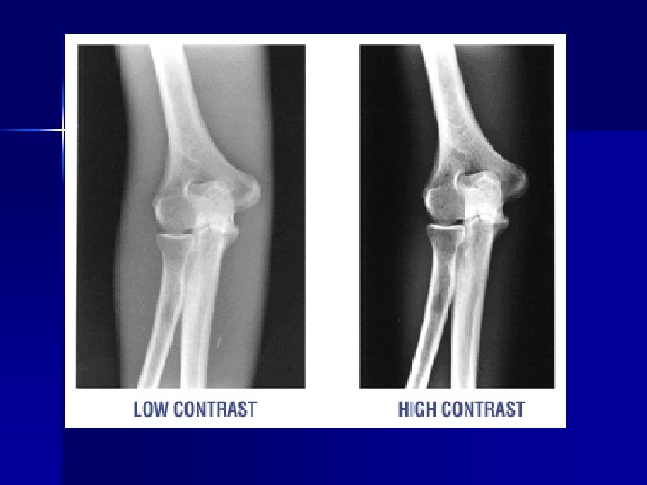
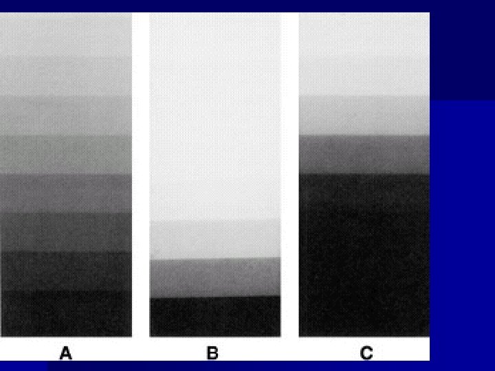
Producing optimal radiographs Contrast Scale Long scale short scale
Scale of Contrast? Which one is “better” How does the k. Vp affect these images?
Short Scale vs. Long Scale
Beam Restriction and Grids
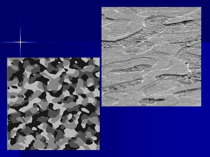
Scatter – Creates fog – Lowers contrast (more grays) n Increases as:
Effects of collimation (beam restriction) on scatter
n Collimate to area of interest reduces scatter and radiation dose to the patient
Grids n A device with lead strips that is placed between the patient and the cassette n Used on larger body parts to reduce the number of scattering photons from reaching the image
GRID NO GRID CONTROLS CONTRAST
Basic Grid Construction 1. Radiopaque lead strips 2. Separated by radiolucent interspace material - Typically aluminum 3. Allow primary radiation to reach the image receptor (IR) 4. Absorb most scattered radiation 5. Primary disadvantage of grid use 1. Grid lines on film
GRIDS
Grid is placed between patient (behind table or upright bucky) & cassette
Grids absorb scatter – prevents it from reaching the image GRID STOPS SCATTER
With Grid No Grid
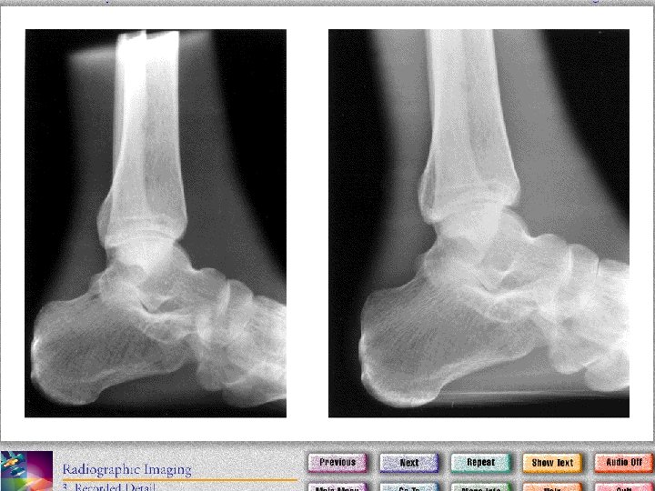
GEOMETRIC Properties n Recorded Detail n DISTORTION – _______ n Magnification – _______ n Elongation n Foreshortening
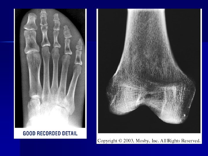
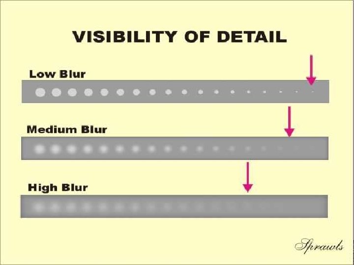
RECORDED DETAIL
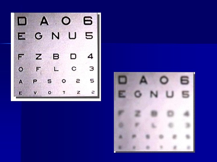
RECORDED DETAIL n The degree of sharpness in an object’s borders and structural details. n How “clear” the object looks on the radiograph
Recorded Detail n The degree of sharpness in an object’s borders and structural details. n Other names: 1. 2. 3. 4.
RESOLUTION TEST TOOLS LINE PAIRS/ MM Depicts how well you can see the differences in structures More lines=more detail
Factors that affect Recorded Detail 1. 2. 3. 4. 5. 6. 7. Geometric unsharpness OID SIZE SHAPE Motion unsharpness (blurring) Intensifying Screens Film Speed / Composition Film – Screen contact Kvp & Mas (density / visibility)
MOTION AKA Blurring
Motion n Can be voluntary or _______ n Best controlled by short exposure times n Use of careful ________ to the pt. n Suspension of pt. respiration n ___________ devices
Decrease Motion Unsharpness n Instruct patient not to move or breath n Use Immobilization devices n Use Short exposure times n Lock equipment in place
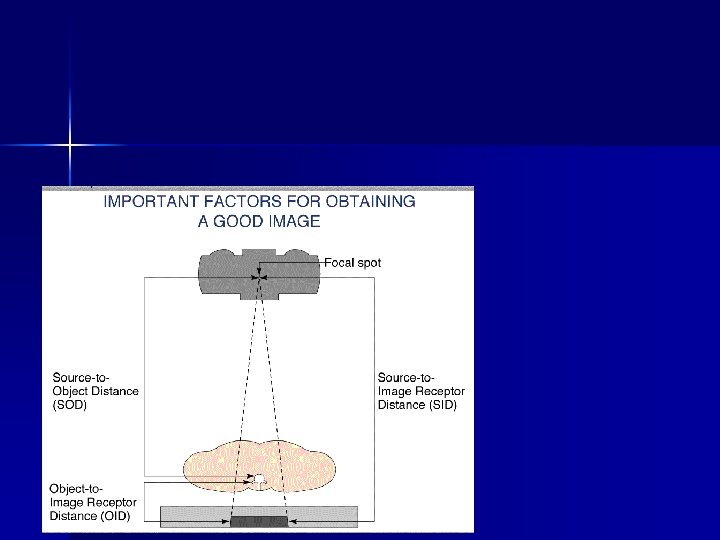
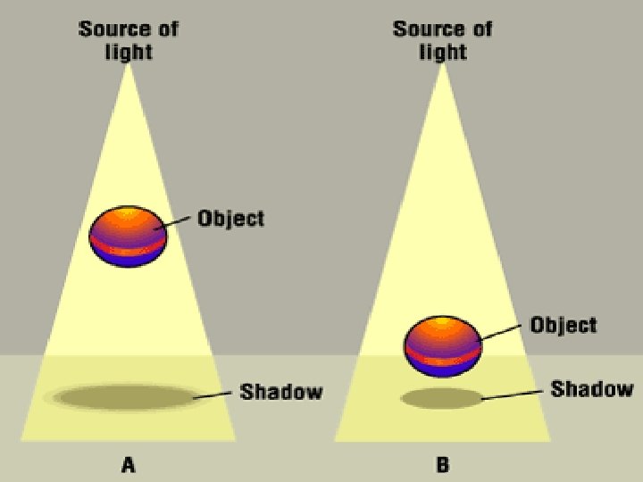
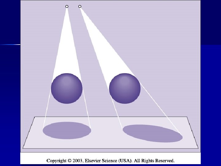
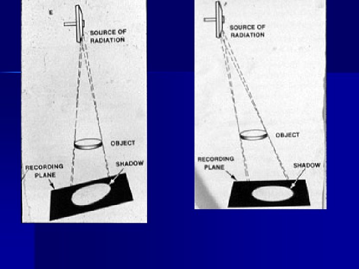
Object Unsharpness n Main problem is trying to image a 3 -D object on a 2 -D film. n Human body is not straight edges and sharp angles. n We must compensate for object unsharpness with factors we can control: focal spot size, SID & OID
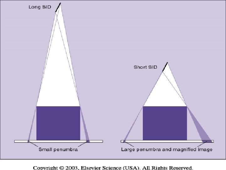
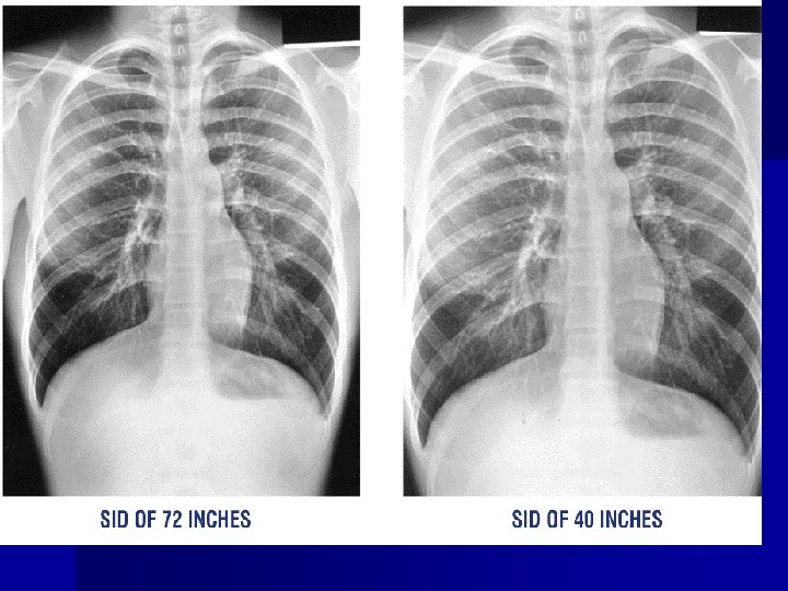
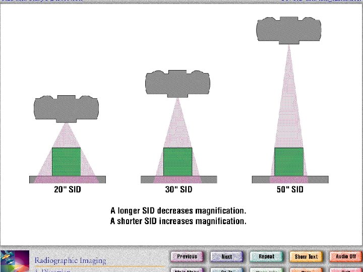
SID Source to Image Distance n The greater the source X-ray tube) to image (cassette) distance, the greater the image sharpness. n Standard distance = 40 in. most exams n Exception = Chest radiography 72 in.
SID n Shine a flashlight on a 3 -D object, shadow borders will appear “fuzzy” -On a radiograph called Penumbra n Penumbra (fuzziness) obscures true border – umbra n Farther the flashlight from object = sharper borders. Same with radiography.
OID Object to Image Distance n The closer the object to the film, the sharper the detail. n OID , penumbra , sharpness n n Structures located deep in the body, radiographer must know how to position to get the object closest to the film.
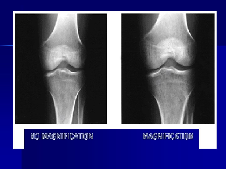
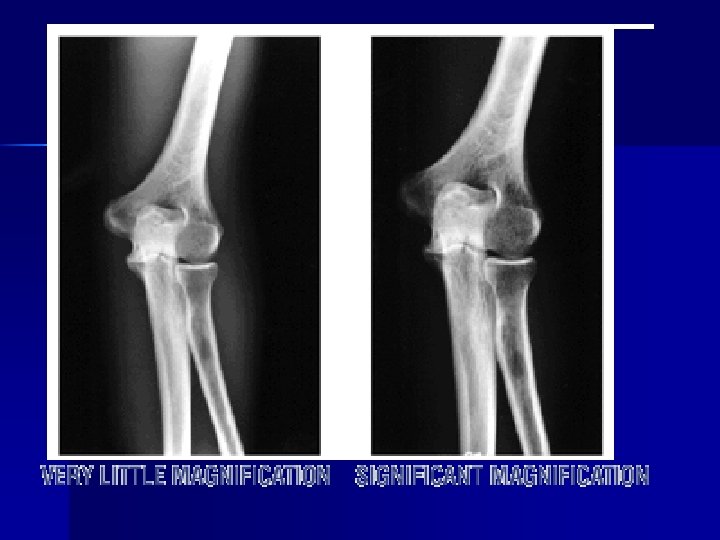
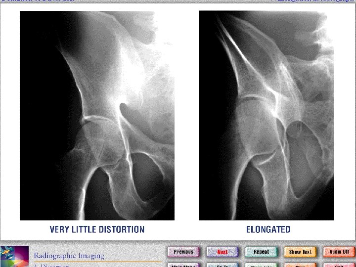
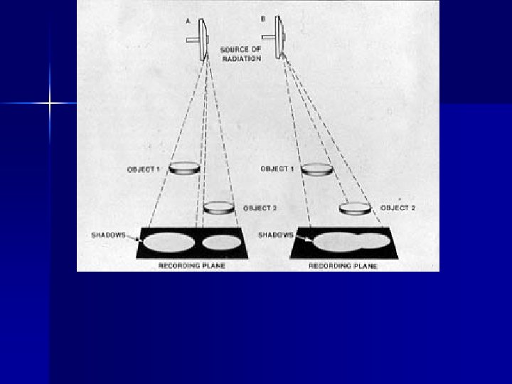
The position of the structure in the body will influence how magnified it will be seen on the image The farther away – the more magnified
Distortion n Misrepresentation of the true size or shape of an object – ________ – size distortion – ________ – shape distortion
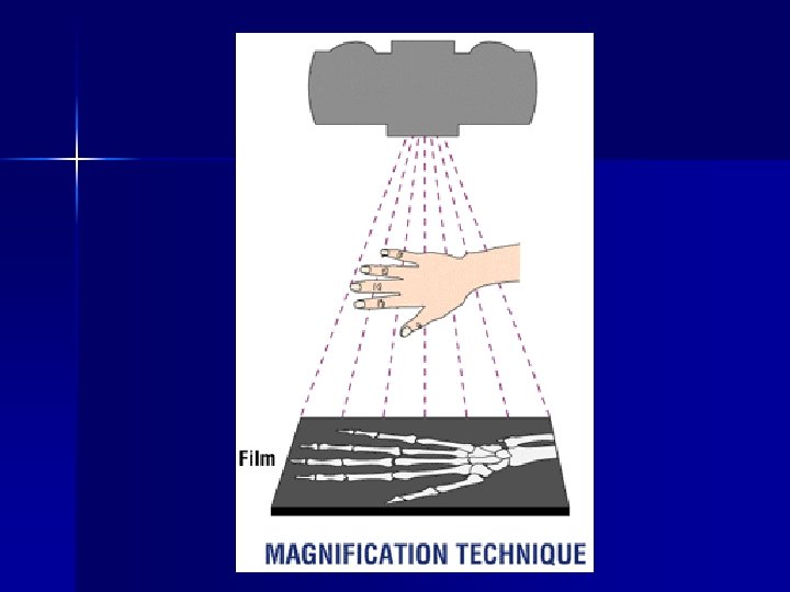
MAGNIFICATION n TUBE CLOSE TO THE PART (SID) n PART FAR FROM THE CASSETTE (OID)
n http: //www. coursewareobjects. com/ob jects/mroimaging_v 1/mod 04 i/0416 a. ht m
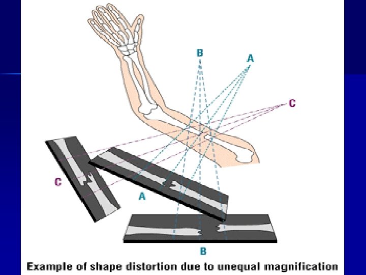
Size Distortion & OID n If source is kept constant, OID will affect magnification n As OID , magnification n The farther the object is from the film, the more magnification
• In terms of recorded detail and magnification the best image is produced with a • ______ OID & _____ SID
Minimal magnification small OID Magnification large OID
Size Distortion & SID n Major influences: SID & OID n As SID , magnification n Standardized SID’s allow radiologist to assume certain amt. of magnification factors are present n Must note deviations from standard SID
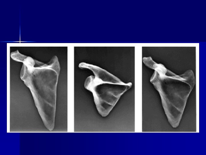
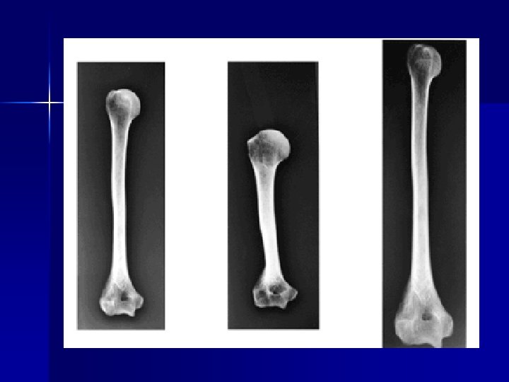
SHAPE DISTORTION Elongation and Foreshortening
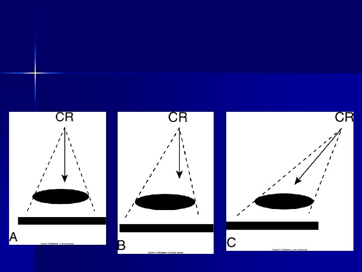
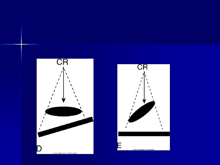
Shape Distortion n Misrepresentation of the shape of an object n Controlled by alignment of the beam, part (object), & image receptor n Influences: Central ray angulation & body part rotation
Image Distortion n When the part to be imaged – does not lay parallel with the IR (cassette) n If the Central Ray is not perpendicular to the part – CR should be at right angle with the cassette
Central Ray Angulation n Body parts are not always 90 degrees from one another n Central ray angulation is used to demonstrate certain details that can be hidden by superimposed body parts. n Body part rotation or obliquing the body can also help visualize superimposed anatomy.
Central Ray n Radiation beam diverges from the tube in a pyramid shape. n Photons in the center travel along a straight line – central ray n Photons along the beam’s periphery travel at an angle n When central ray in angled, image shape is distorted.
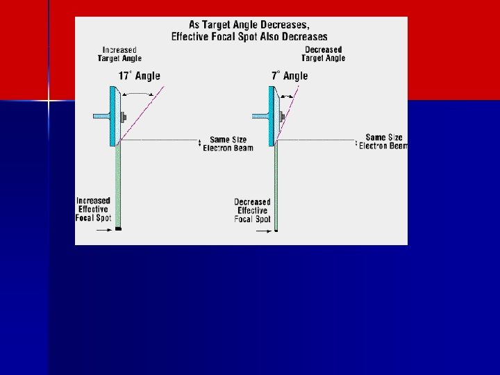
Focal Spot Size n Smaller x-ray beam width will produce a sharper image. n Fine detail = small focal spot (i. e. small bones) n General radiography uses large focal spot n Beam from penlight size flashlight vs. flood light beam
ANODE
FOCAL SPOT ANGLE SMALLER ANGLE – SMALLER BEAM AT PATIENT
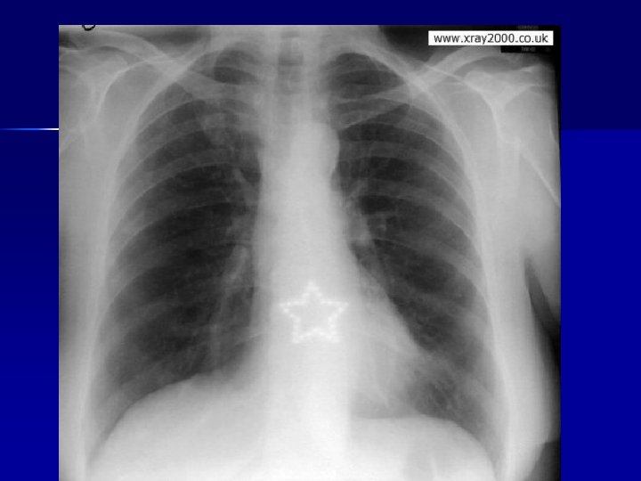
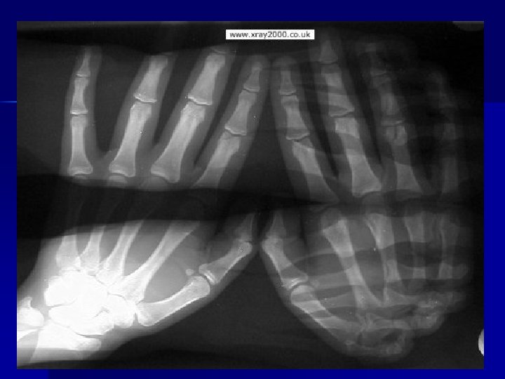
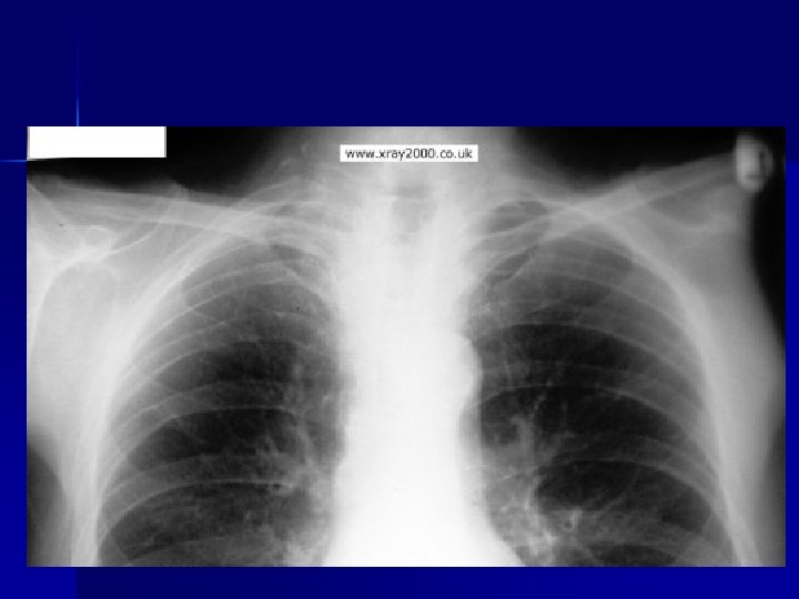
http: //www. xray 2000. co. uk/
Artifacts - Types n Processing Artifacts n Exposure Artifacts n Handling & Storage Artifacts
Processing Artifacts Emulsion pickoff n Chemical fog n Guide-shoe marks n Water marks n Chemical spots n Guide-shoe & roller scratches n
Exposure Artifacts Motion n Improper patient position n Wrong screen-film match n Poor film/screen contact n Double exposure n Warped cassette n Improper grid position n
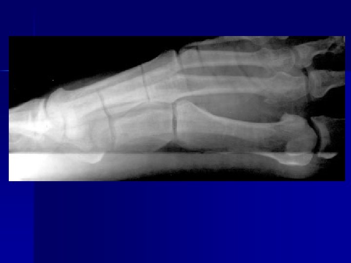
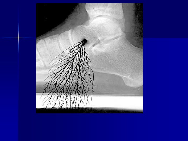
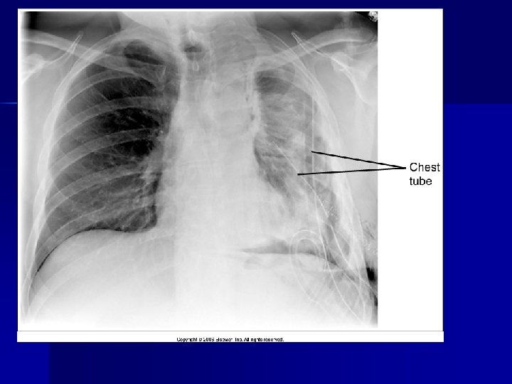
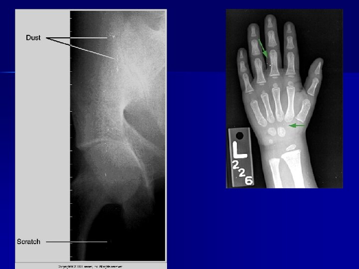
Artifact
Handling & Storage Artifacts Light fog n Radiation fog n Static n Kink marks n Scratches n Dirty cassettes n
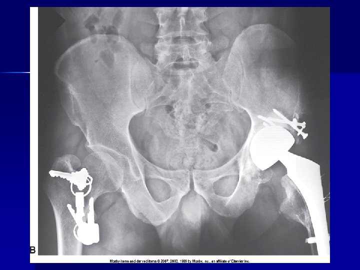
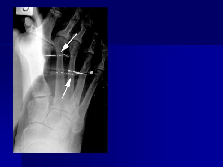
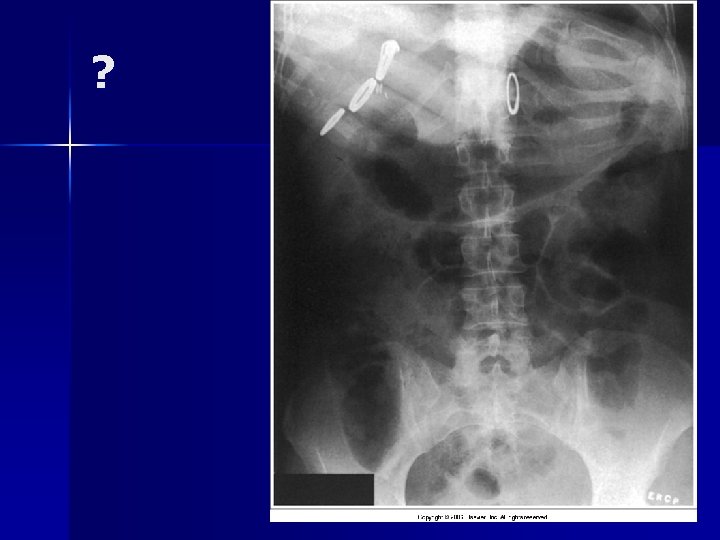
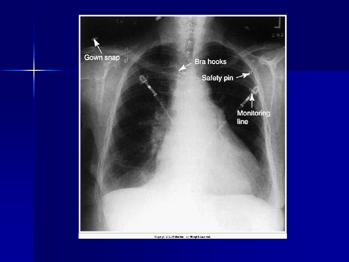
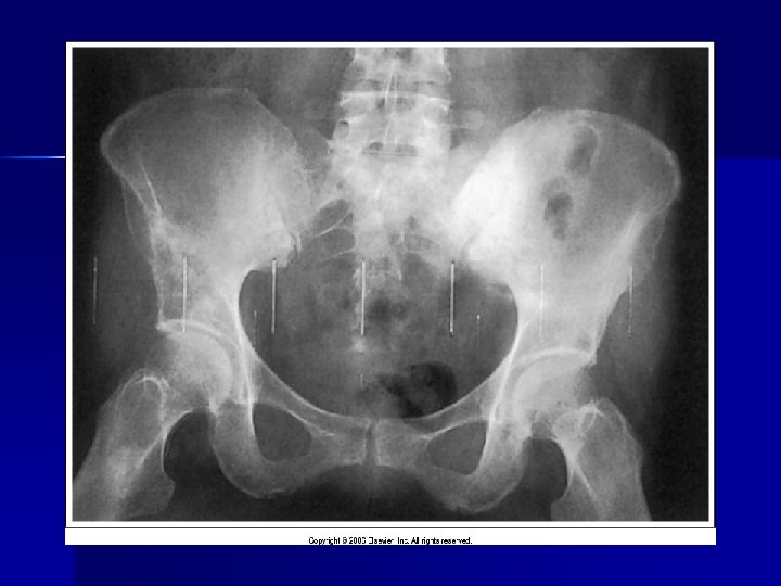
Pt clothing
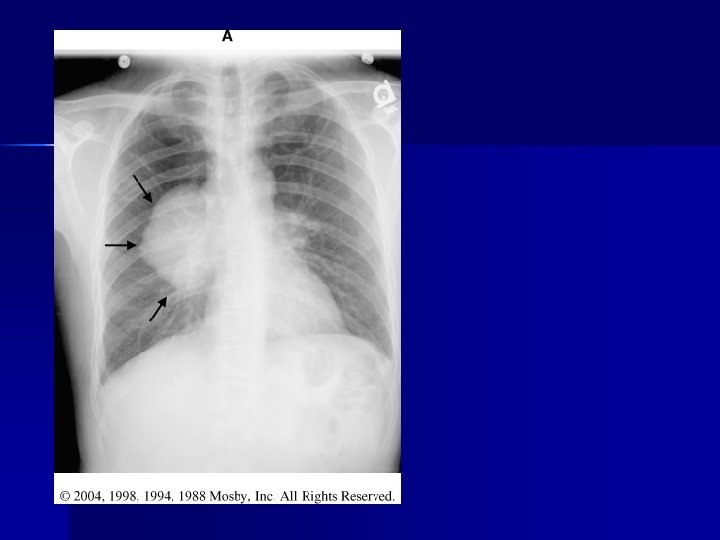
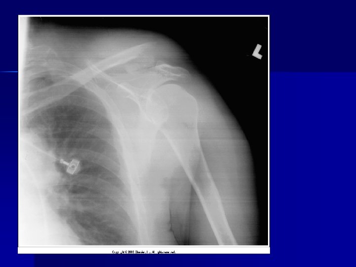
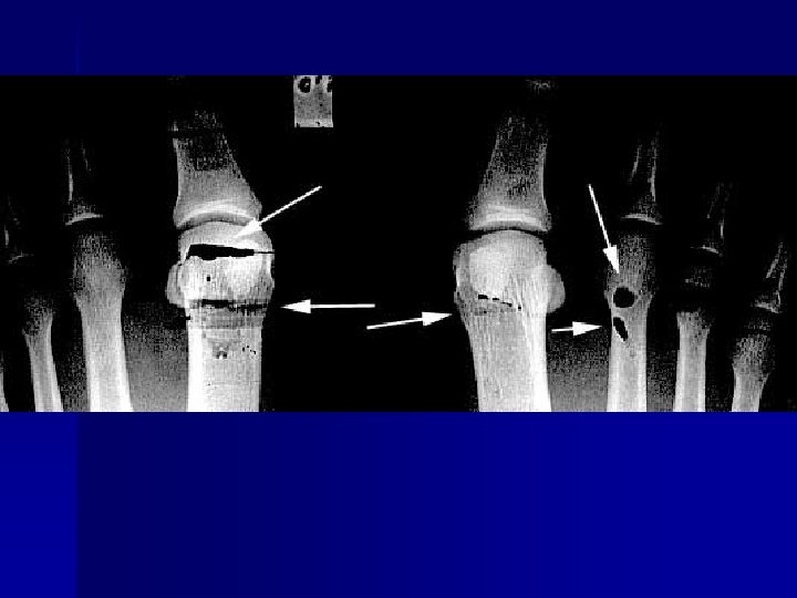
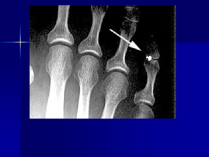
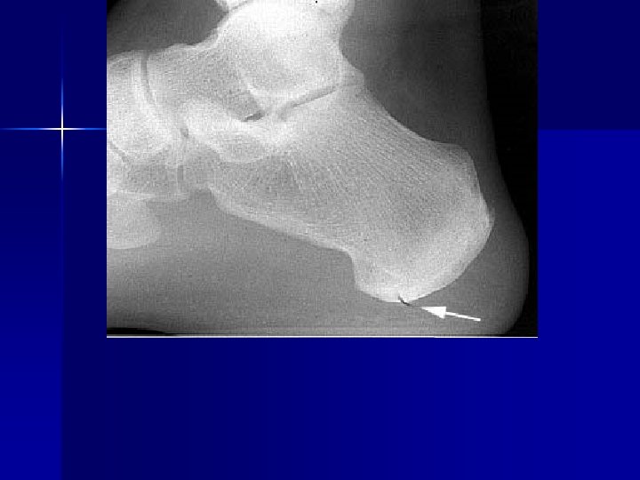
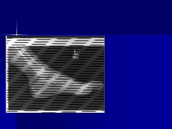
PATHOLOGY NOT ARTIFACT
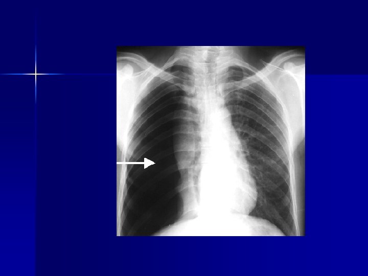
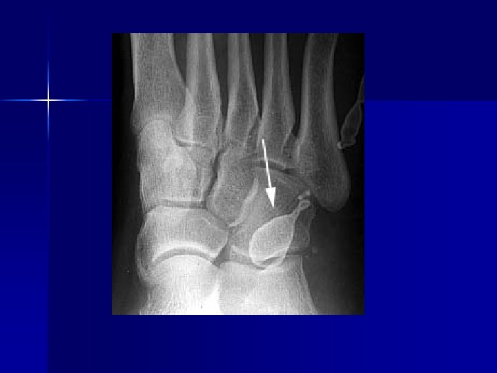
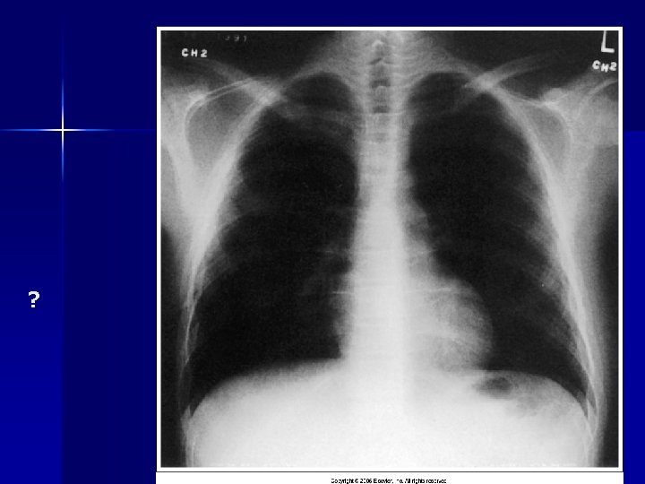
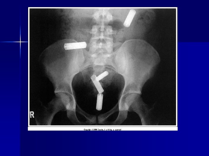
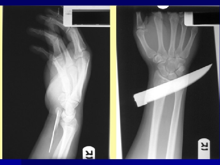
Name & cause of this?
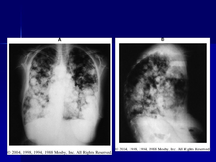
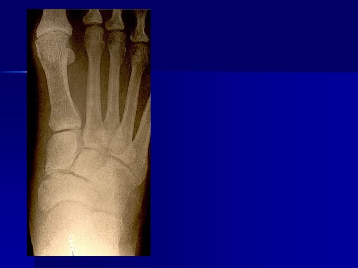
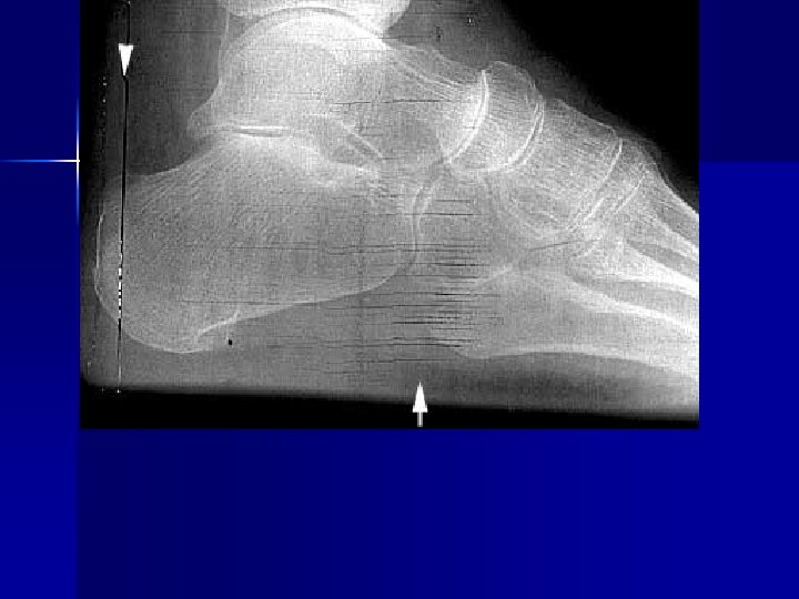
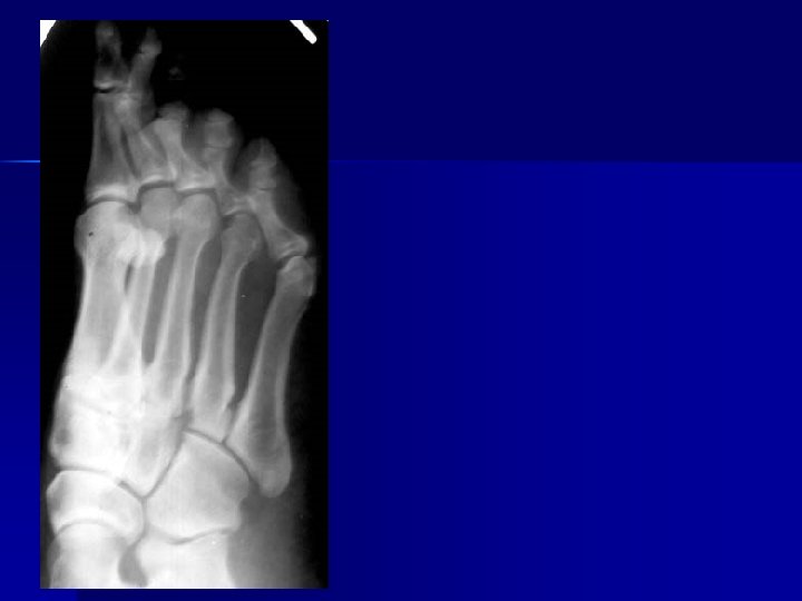
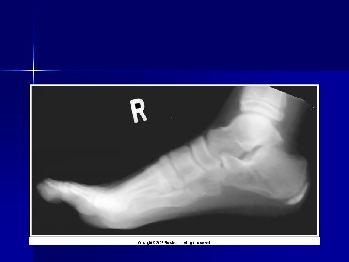
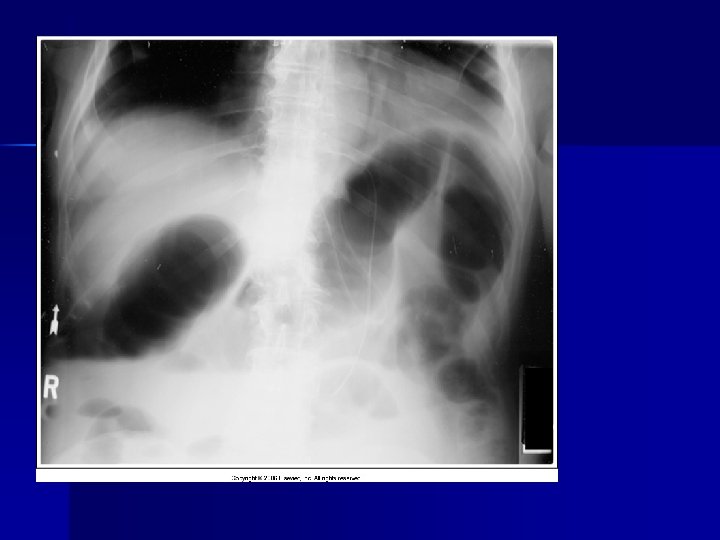
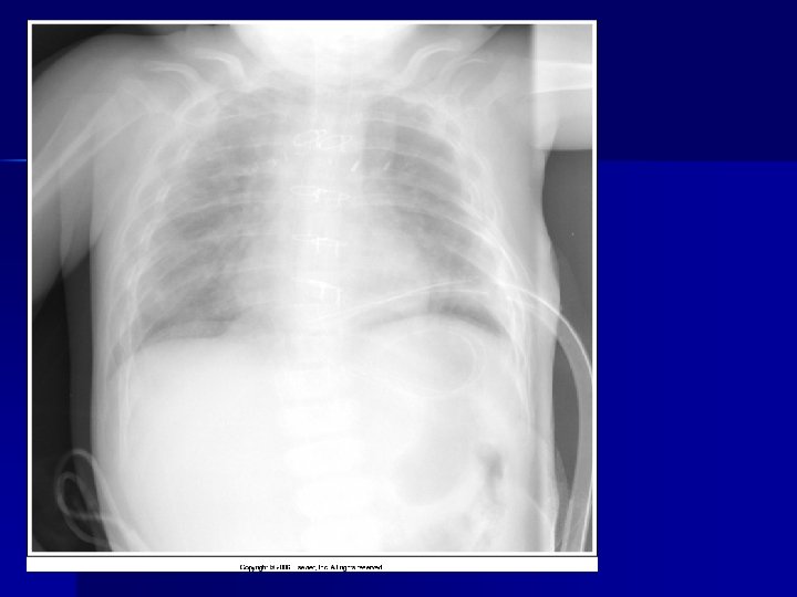
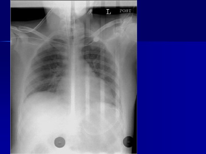
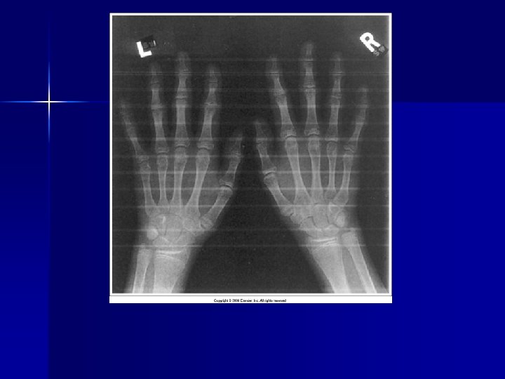
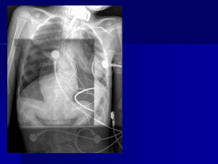
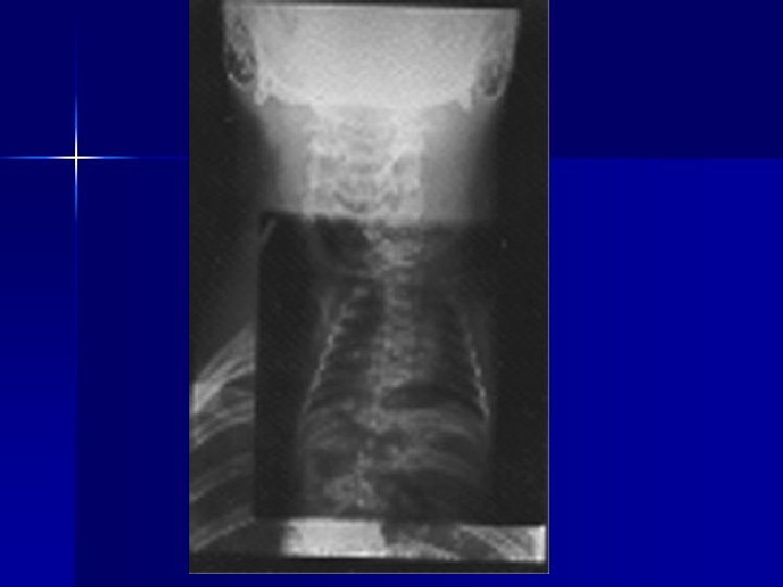
Evaluating Images What do you think?
n n n Does this show good detail? Is all of the anatomy present? How is the density / contrast?