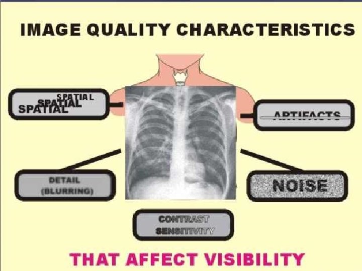
Components of Radiographic Image Quality Radiologic Technology 244


")


 Distortion (x-ray beam not centered over object &")

 due to x-ray beam not being")

 l PART FAR FROM")


 l Calcium Tungstate l l")


 What does it mean? l Name the two types of screen")

")
 Red safe light")


- Slides: 83
Components of Radiographic Image Quality Radiologic Technology 244 created: Fall 2005 Rev 12 -01 -2009
Review handouts
Main Factors Affecting Recorded Detail l k. Vp & m. As l l l l Technique Selection (Time) Motion Object Unsharpness Focal Spot Size SID (Source to Image Distance) OID (Object to Image Distance) Material Unsharpness/ Film Screen Combo
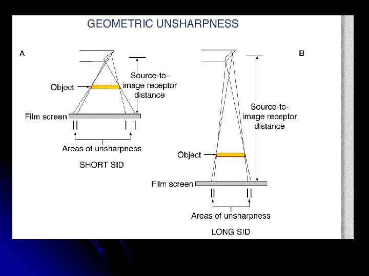
Factors that affect Recorded Detail Geometric unsharpness OID SIZE SHAPE l Motion unsharpness (blurring) l Intensifying Screens l Film Speed / Composition l Film – Screen contact l Kvp & Mas (density / visibility) l
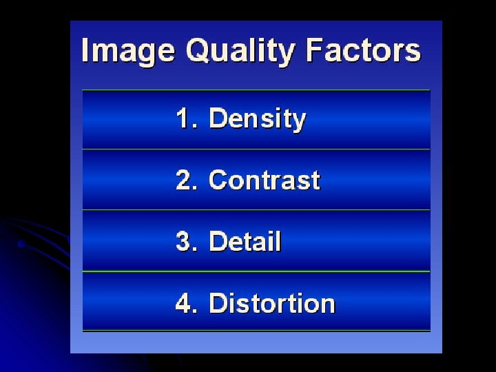
GEOMETRIC QUALITIES l DETAIL l DISTORTION l MAGNIFICATION
DETAIL l. The degree of sharpness in an object’s borders and structural details. l. How “clear” the object looks on the radiograph
Recorded Detail l Other names: -sharpness of detail -definition -resolution -degree of noise
What are these What does they measure?
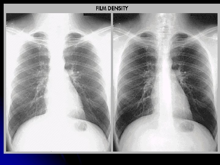
Factors Affecting DENSITY PATIENT THICKNESS, PATHOLOGY l MAS & KVP l SID l
PO OR DETAIL GOOD DETAIL
Motion Can be voluntary or involuntary l Best controlled by short exposure times l Use of careful instructions to the pt. l Suspension of pt. respiration l Immobilization devices l
Decrease Motion Unsharpness Instruct patient not to move or breath l Use Immobilization devices l Use Short exposure times l Lock equipment in place l
NAME 4 CAUSES
Blurring of image due to patient movement during exposure.
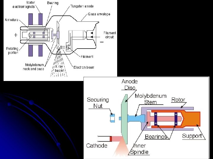
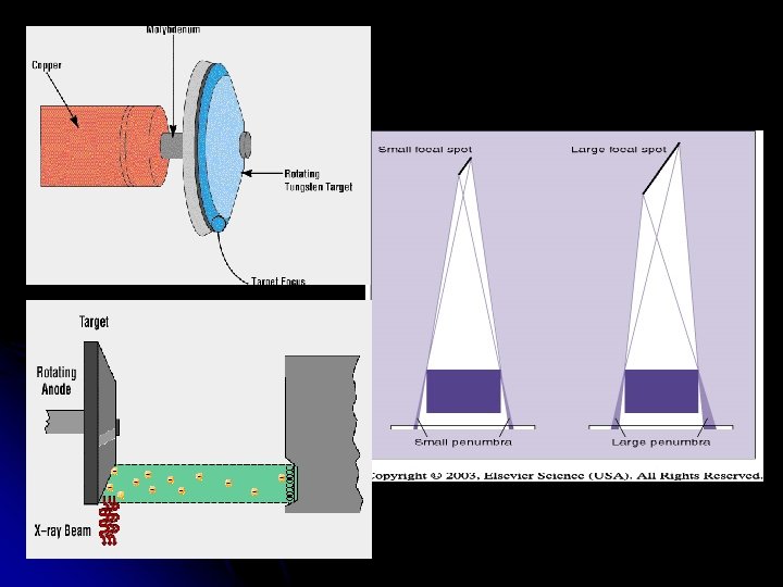
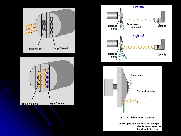
Focal Spot Size l l Smaller x-ray beam width will produce a sharper image. Fine detail = small focal spot (i. e. small bones) General radiography uses large focal spot Beam from penlight size flashlight vs. flood light beam
FOCAL SPOT ANGLE
Object Unsharpness l l l Main problem is trying to image a 3 -D object on a 2 -D film. Human body is not straight edges and sharp angles. We must compensate for object unsharpness with factors we can control: focal spot size, SID & OID
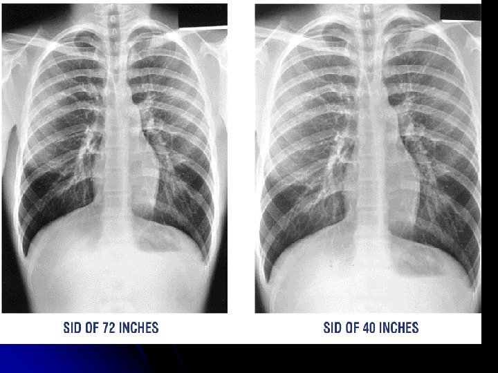
SID Source to Image Distance The greater the distance between the source of the x-ray (tube) and the image receptor (cassette), the greater the image sharpness. l Standard distance = 40 in. most exams l Exception = Chest radiography 72 in. l
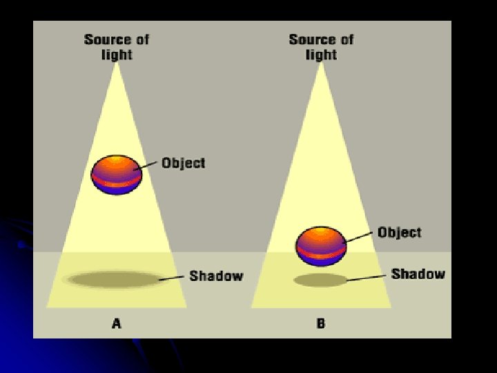
SID Shine a flashlight on a 3 -D object, shadow borders will appear “fuzzy” On a radiograph it’s called _______ l A true border – _____ l Farther the flashlight from object = sharper borders. Same with radiography. l
OID Object to Image Distance The closer the object to the film, the sharper the detail. l OID , penumbra , sharpness l Structures located deep in the body, radiographer must know how to position to get the object closest to the film. l
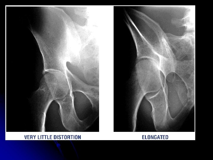
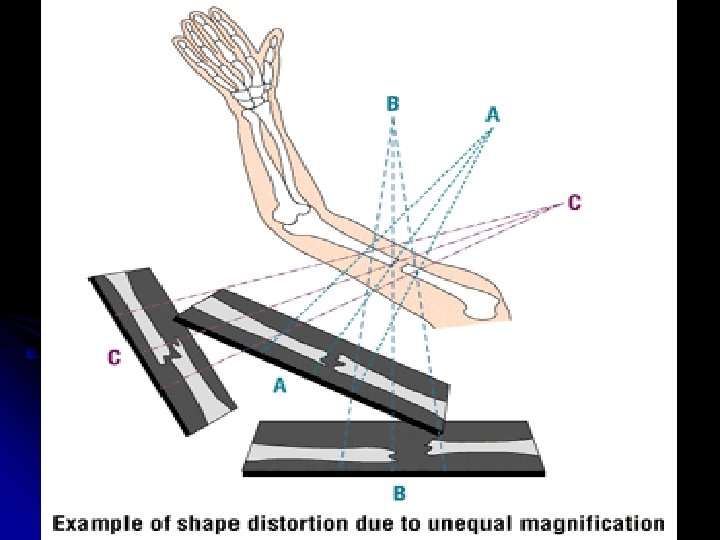
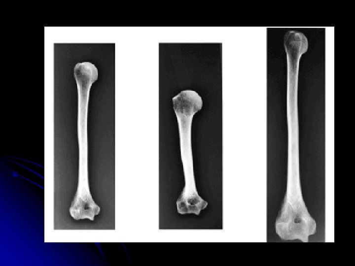
Distortion l Misrepresentation of the true size or shape of an object MAGNIFICATION (size distortion) TRUE DISTORTION (shape distortion)
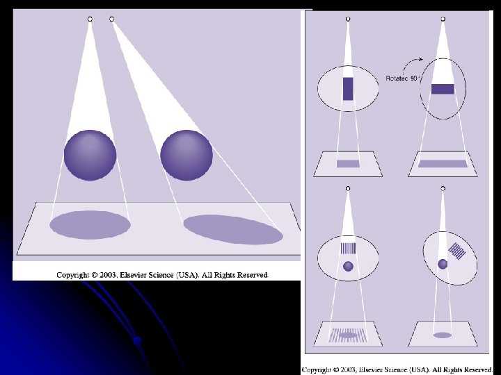
Shape Distortion Misrepresentation of the shape of an object l Controlled by alignment of the beam, part (object), & image receptor l Influences: Central ray angulation & body part rotation l
Elongation Foreshortened Normal
Distortion (object & film not parallel) Distortion (x-ray beam not centered over object & film)
Central Ray Radiation beam diverges from the tube in a pyramid shape. l Photons in the center travel along a straight line – central ray l Photons along the beam’s periphery travel at an angle l When central ray in angled, image shape is distorted. l
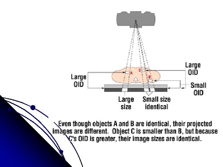
Distortion of multiple objects in same image (right) due to x-ray beam not being centered over objects.
Central Ray Angulation Body parts are not always 90 degrees from one another l Central ray angulation is used to demonstrate certain details that can be hidden by superimposed body parts. l Body part rotation or obliquing the body can also help visualize superimposed anatomy. l NAME 3 EXAMPLES l
MAGNIFICATION caused by: l TUBE CLOSE TO THE PART (↓SID) l PART FAR FROM THE CASSETTE (↑ OID) Compensate for MAG : ↑ OID by ↑ SID = “increase SID 7” for every 1” OID”
Size Distortion & SID Major influences: SID & OID l As SID , magnification l Standardized SID’s allow radiologist to assume certain amt. of magnification factors are present l Must note deviations from standard SID l
In terms of recorded detail and magnification, the best image is produced with a small OID and a large SID.
l What can be done to improve the detail with a large OID?
Use a smaller FS
40” SID VS 72” SID
Size Distortion & OID If source is kept constant, OID will affect magnification l As OID , magnification l The farther the object is from the film, the more magnification l
How can it be measured?
Measuring % of Magnification SID SOD
Measuring % of Magnification l What is the % of mag when you have a 72” SID and 4” OID? l DO the math…………
Material Unsharpness Equipment used can contribute to image unsharpness l Fast film/screen combinations = decrease in image sharpness l Slower film/screen combinations = increase in image sharpness l
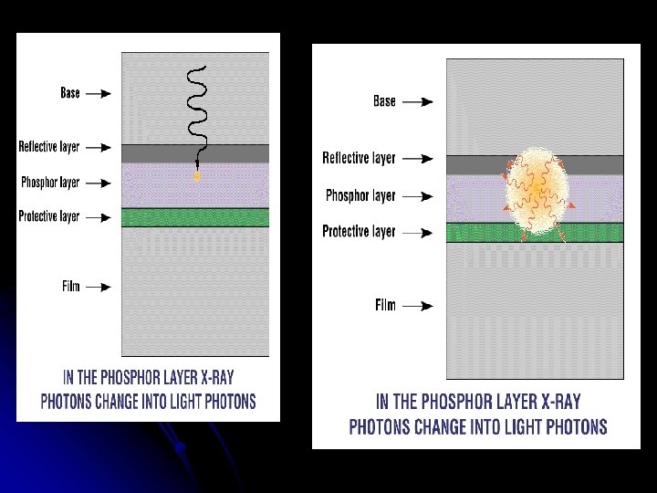
Intensifying screens l Lower patient dose l Changes resolution of image l slow screens less LIGHT = better detail l Faster – less detail (more blurring on edges)
Intensifying Screens: Review Located inside the cassette (film holder) l Calcium Tungstate l l Blue l to purple light Rare Earth l Green light & Ultraviolet
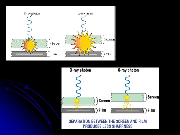
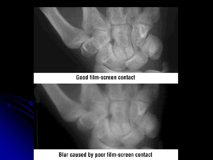
POOR SCREEN CONTACT l FOAM BACKING HELPS TO PLACE INTENSIFYING SCREENS IN DIRECT CONTACT WITH THE FILM – NO GAPS l IF GAPS – MORE LIGHT CAN BE EMITTED IN SPACE, CAUSING THE IMAGE TO BE OF POOR DETAIL
WIRE MESH SCREEN CONTACT TEST
Screen Speed l Efficiency of a screen in converting x-rays to light is Screen Speed.
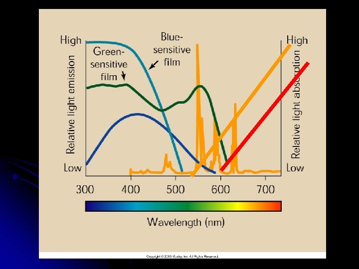
Spectral Matching (F/S) What does it mean? l Name the two types of screen phosphors l What light spectrum do they emit? l
Spectral Sensitivity Film is designed to be sensitive to the color of light emitted by the intensifying screens. l Blue LIGHT– Conventional Calcium Tungstate screen l Green, Yellow-Green LIGHT l – Rare Earth screen
Spectral Matching (F/S systems)
Spectral Matching (F/S systems) Red safe light
Safe lights What wattage bulb? l Distance from counter top? l
Review of Film Characteristics Size of silver halide crystals & emulsion thickness determine speed of film and degree of resolution Speed – the response to photons l Resolution – the detail seen l
l What are these l What are they made of
Film Speed / Crystal size l Larger crystals or Thicker crystal layer Faster response= less detail, and less exposure (chest x-ray) l Finer crystals / thinner crystal layer =Slower response, greater detail, more exposure (extremity)
IMAGE ON FILM l SINGLE EMULSION = BETTER DETAIL l DOUBLE EMULISON = LESS DETAIL l PARALLAX With double emulsion – an image is created on both emulsions – then superimposed – slight blurring of edges
Extremity vs Regular cassettes
QUANTUM MOTTLE Film grain, or graininess, refers to the tiny black spots that make up the visible image, one grain from each silver halide crystal exposed MORE COMMON IN CR SYSTEMS NOW NOT ENOUGH PHOTONS TO CREATE IMAGE
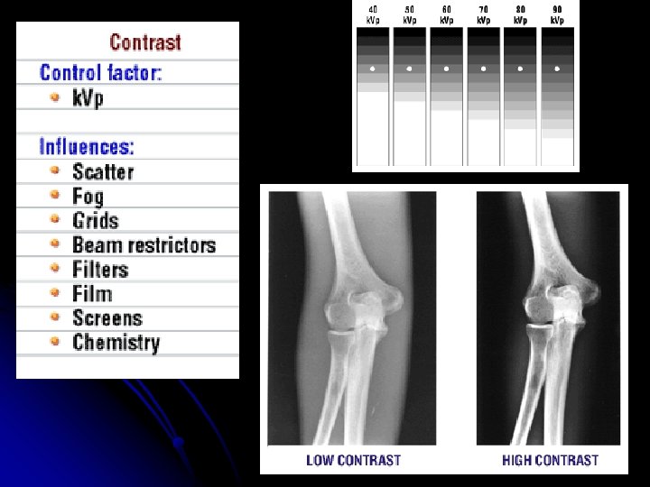
Factors Affecting m. As l LIST 6 factors
Factors Affecting m. As l l l Patient factors: size of pt. , density of tissue, pathology k. Vp Distance - how Grids Film/Screen Combinations Processing
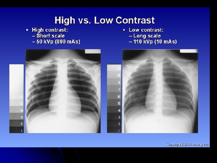
Technique /Denisty CHANGES
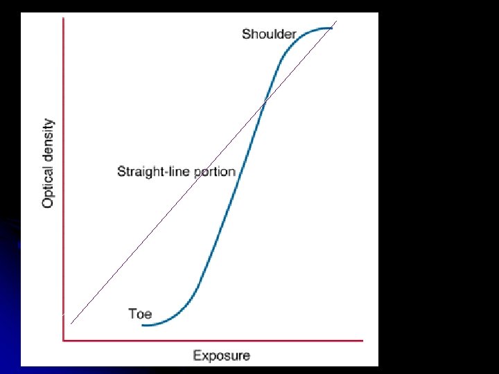
Log denisty H & D curve
l l l a densitometer, measures film blackness. Film blackness is the relationship of the intensity of the light that hits the film from the view box (incident intensity) to the intensity of the light transmitted through the film (transmitted intensity). These measurements plotted on a graph produce a characteristic curve. The limitations of the human eye determine the useful density range in diagnostic radiography. The diagnostically useful range of densities is 0. 25 to 2. 5. The later module on exposure calculation considers this in more detail.
Film latitude ? What does it mean how does it plot on the curve?
Main Factors Affecting Recorded Detail k. Vp & m. As l Motion l Object Unsharpness l Focal Spot Size l SID (Source to Image Distance) l OID (Object to Image Distance) l Material Unsharpness/ Film Screen Combo l