Radiographic Techniques in Dental Implants Introduction Radiographic examination


: Class I…. . almost")

: D 1……. . thick compact bone.")


 is the radiograph of choice. • These")


: • CT scans provide the clinician with the most detailed")


 will produce")


- Slides: 56
Radiographic Techniques in Dental Implants
Introduction: • Radiographic examination is a central part of implant treatment from the planning phase to the long-term evaluation of treatment success. • In combination with clinical examination they may provide enough information to plan treatment without resorting to more complex imaging techniques.
• Tomographic examinations provide: 1. Cross-sectional and 3 D images. 2. Information about bone quantity. 3. Some indication of the bone quality available, (i. e thickness of the cortices as well as an approximation of the density of the cancellous bone).
Classification of bone quantity & quality: • Numerous classified the bone quantity & quality in the edentulous maxilla & mandible as a guide for selection of patients for osseointegration.
Classification of bone quantity: A……most of the alveolar ridge is present. B……moderate alveolar ridge resorption has occurred. C…. . Only basal bone remains. D…. . some resorption of basal bone has taken place. E……Extreme resorption of the basal bone has taken place.
Cross section of bone resorption pattern according to Lekholm &Zarb
Classification of bone quality according to Lekholm & Zarb (1985): Class I…. . almost the entire jaw is comprised of homogenous compact bone. Class II…. . a thick layer of compact bone surrounds a core of dense trabecular bone. Class III…. . a thin layer of cortical bone surrounds a core of dense trabecular bone. Class IV…. . a thin layer of cortical bone surrounds a core of low density trabecular bone.
Diagram indicating quality of bone according to Lekholm & Zarb
Classification of bone quality according to Misch (1990): D 1……. . thick compact bone. D 2……. thick, dense to porous cotical bone surrounds coarse trabecular bone. D 3……. . thin , porous , compact bone surrounds loosley structured cancellous bone. D 4……. loose , thin, cancellous bone.
Screening: • A screening radiograph should give the clinician an indication of: ØThe overall status of teeth and supporting bone. ØThose sites where it is possible to place implants using a straight-forward protocol.
ØThose sites where it is unlikely that implants can be placed without using complex procedures such as grafting. ØThose sites where it is inadvisable to recommend implants. ØAnatomical anomalies or pathological lesions.
Panoramic radiography: • Dental Panoramic Tomography (DPT) is the radiograph of choice. • These are narrow beam rotational tomographs which use two or more centres of rotation to produce an image of the dental arches. • They provide an image within a predefined focal trough of both upper and lower jaws and as such give:
1. A reasonable approximation of bone height. 2. The position of the inferior dental neurovascular bundle. 3. The size and position of the maxillary antra. 4. Any pathological conditions which may be present.
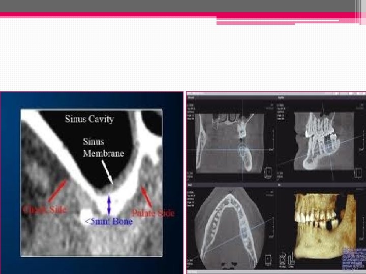
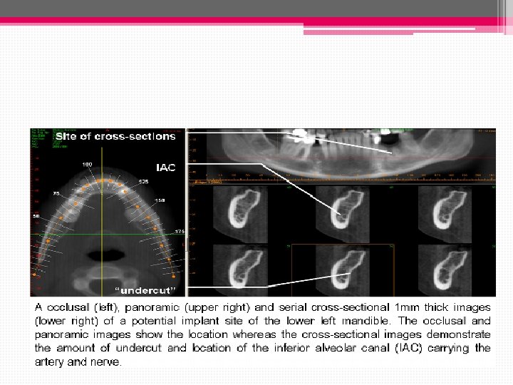
Indications/uses: • Initial evaluation of bone dimensions & in screening for the detection of pathologic conditions when planning for dental implants. • Provides approximate information regarding the location & dimensions of the maxillary sinus, nasal cavity, inferior alveolar canal & mental foramen.
Limitations: • Magnification of up to 25% which result in error of up to 3. 0 mm. • The poor image resolution & unpredictable image distortion limits usefullness when planning implant spacing & numbers.
• May provide information to determine VD but is unreliable for measurements in the horizontal direction & for assessing bone quality. ü The radiation dosage of a DPT is approx. 0. 007 to 0. 014 m. Sv which is less than a full mouth series of periapical radiographs.
Supplemental radiograph: • the lateral cephalogram can give more detail of the morphology of both jaws close to the midline, and this can be useful when planning overdenture treatment. • Standard occlusal views may also aid in assessing the bone morphology in the lower jaw.
Supplemental radiographs Lateral Ceph. Lower occlusal
Dental Panoramic Tomogram of a patient with oligodontia. It clearly shows very little bone height in the right maxillary edentulous region.
Periapical radiography: • Indications : • Allow accurate horizontal measurement such as the proximity of adjacent roots. • Permits an accurate evaluation of the bone response adjacent to dental implants. • Recommended to evalute passive fit between implant component.
• Radiography for single tooth replacement or small bridges in individuals with little bone loss can normally be accomplished by intra-oral radiographs taken with a long cone paralleling technique.
Advantages: 1. Highly quality. 2. Low cost. 3. Low radiation exposure. 4. Readily available.
Limitations: • Vertical & horizontal linear measurements are accurate if paralling techniques are used to prevent image distortion. • Does not provide a cross sectional view of the bone & only a small area of the jaw is visible.
Periapical view Before sinus lifting After sinus lifting
Linear tomography: • LT is becoming less useful. • Cross-sectional images of any portion of the maxilla & mandible can be obtained by LT. • The radiographic source & film rotate around the plane of interest , so that all other planes are blurred.
Evaluation and planning: Radiographic stents: • A stent which mimics the desired tooth setup is constructed and radiographic markers usually made of gutta percha or another radio-opaque material placed within it. • The choice of radiographic marker is important in that it should be visible on the radiographic image but not interfere with scan.
Implant site identified by GP marker.
• Alternatively, if the patient has a suitable acrylic denture, radiographic markers may be placed within occlusal or palatal cavities cut in the acrylic teeth. • The denture can also be replicated in clear acrylic to provide the radiographic stent.
Advantages: 1. It provides information about the planned final restoration. 2. In the edentulous patient they serve to stabilize the position of the jaws while the radiographs are being taken. 3. It can also provide the radiograph with a true occlusal plane from which to orientate the axial scans.
Surgical stent for implant
Computerized tomography (CT scan): • CT scans provide the clinician with the most detailed images currently available. • The cost and high radiation dose make their use is often limited to more complex cases such as: ØFull arch maxillary reconstructions. Ø Bilateral posterior mandible imaging. Ø Patients require extensive grafting procedures.
• CT uses x-rays to produce sectional images as in conventional tomography. • New generation helical CT scanners are faster and have significantly lower radiation dose. • The scans should be limited to the area of interest and avoid radiosensitive tissues such as the eyes.
CT scan images: • Standard radiographic negative images on large sheets. • Positive images on photographic paper often in book form • Images for viewing on a computer monitor.
• Heavy metals(large posts in root canals or heavily restored teeth) will produce a scatter-like interference pattern if they are present in the slice under examination thus result in interference in all the generated sectional images. • Extensive interference may render a CT scan unreadable. .
Scatter artifact in “star” pattern from several metallic restorations and surgical screws.
How to avoid it? • A Compromise has to be made in the direction of scanning or a different method of examination chosen ( scan ora). • By removing the offending metal prior to examination if appropriate in the overall treatment plan.
Scan Ora: • It is a new generation of sophisticated tomographic devices most similar to conventional DPT machines, but with facilities to generate high quality sectional images. • In contrast to CT scanning where the sectional images are software generated, the Scan Ora produces a tomographic image directly onto film.
• It uses complex broad beam spiral tomography and is able to scan in multiple planes. • DPT image is produced from which the sites which require sectional tomographic data are determined. • Because the scan sections are thicker and fewer the overall patient dose is much less than a CT scan.
• In order to facilitate planning using images at different magnifications, transparent overlays depicting implants of various lengths and diameters at the corresponding magnifications can be superimposed directly on the radiograph. • These provide a simple method of assessing implant sites and implant placement at different angulations.
Scan Ora This shows a cross sectional image of the maxillary ridge A Scan Ora section through the anterior mandible
Panoramic view obtained during scanning
Cone beam CT: • Cone beam scans are 3 -dimensional X-rays that show the height, width and depth of bone. • Aids in locate vital structures, like nerves and blood vessels.
• It can be used to virtually place a dental implant using a sophisticated software program. • This technology improves dental implant success rates, enabling a more predictable result when the final crown is inserted
• The software allows us to have a surgical guide fabricated which will fit in the pt’s mouth so that implants can be placed in a position that precisely matches the position of the virtual implant on the CT scan. • The images that CT scans produce are not distorted and can be used to measure true length with incredible accuracy and precision.
CBCT machine
Cone beam CT
Perioperative and follow-up radiograph: • Intra-oral radiographs may be useful at the time of implant placement allowing visualization of drills or direction indicators and their relation to adjacent teeth or anatomical structures. • At second stage surgery radiographs may be required to ensure full seating of abutments when direct visualization has not been possible at the time of surgery.
• During the prosthetic phase it is essential to ensure full seating of components and frameworks. • It is essential that radiographs are taken at 90° to the long axis of the implant under examination and therefore, it is recommended to use long cone parallel radiographs
• Baseline radiographs to show crestal bone levels and the state of the peri-implant bone should be taken as part of normal documentation at the time of fitting the final prosthesis. • These should be repeated on an annual basis for the first 2 or 3 years to establish that the bone levels are stable.
• some initial bone loss will occur during the first year of function with some implants but that a steady state should then be established thereafter.
• Many of the problems which arise during treatment or once the prosthesis is in function are most readily diagnosed using standard intra-oral views these include: Ø Burnt bone syndrome Ø Bone loss ØComponent loosening ØScrew breakage Ø Implant fracture Ø Adjacent endodontic lesions Ø Loss of integration.
Conclusion: • Radiographs play an important part in the successful planning and execution of implant treatment. • It is important to have an understanding of the different techniques available and their appropriate application.
• They are an important part of the patients records and as such constitute a significant proportion of the medico-legal documentation of the patient. • It is the responsibility of the clinician to ensure that radiographs are appropriate, readable and are retained and repeated at accepted intervals throughout treatment and follow-up.
Thanks