Unit 8 Floor Framing Starting out Once the


 • The platform (floor) is built on top of the")


. • The most")


- Slides: 63
Unit 8 Floor Framing
Starting out • Once the foundation has been completed and the concrete has set up, floor framing can begin. • This task must be completed before backfilling can begin, to avoid damaging the foundation walls. • The floor helps the foundation withstand the pressure place on it by the soil.
The builders design will dictate the type of framing used. Other factors that will influence building methods are; • soil conditions • climate • available materials • the carpenters experience • owners preference
One Story Figure 8 -1 p 179
1 ½ Story
Two Story
Split level
Bi-Level
Platform Framing • Also known as western framing. • Used for most modern construction. • Also used for light construction (Non commercial applications)
Platform Framing (Cont. ) • The platform (floor) is built on top of the foundation walls. • It provides a work area for construction and raising of walls. • Wall sections are one story high. 8 feet in most cases but may be higher in special cases. • The exterior walls and interior load bearing partitions support platforms of upper levels.
Balloon Framing • This type of framing is not often used today. • Many older homes are balloon frame construct. • The studs in the walls run from the sill to the rafter plate. • The ends of the second floor joists are supported by a ribbon let in to the studs of the walls.
Figure 8 -5 p 182 text
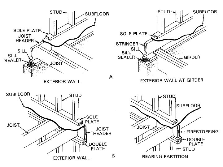
Sill Construction • This is a wood member that is attached to the foundation by bolts. • Are to be constructed with a rot resistant material (pressure treated lumber) • Is located between the platform and the top of the foundation wall. • A seal is placed between the foundation wall and the sill. • The first floor platform will rest on the sill.
Installing Sills • J-bolts or other metal fasteners are placed along the top of the concrete foundation wall before the concrete sets up. • A seal is placed on top of the foundation wall before the sill is installed to help seal the house air tight. (the seal is usually made of foam) • The sill is set in the thickness of the exterior wall sheathing so when the sheathing is installed it is flush with the foundation wall.
Installing Sills cont. • Holes are drilled in the sill at the location of each J-bolt. • The sill is then installed over the sill seal and J-bolts. • Washers are placed on the J-bolts and tightened sandwiching the gasket between the sill and top of the foundation wall.
Fig 8 -24 p 188 text
Video master 8 -2
Joists • Joists are the support beams for a floor (platform). • The most common spacing is 16”o. c. but 12” and 24” may also be used in some cases. • They span the distance between exterior walls. • Often the span is greater than the distance one Joist can span safely. • For this reason girders or load bearing wall are used to keep these distances within code requirements.
Joists cont. • Joists rest on top of the foundation wall (on top of sill plate) on one end and on the girder or load bearing wall at the other. • So they are said to extend from the foundation wall to the girder. • The ends of joists at the exterior wall are all nailed to what is known as a header joist
Fig 8 -25 page 188 text
Fig 8 -26 A page 189 text.
Video master 8 -1 p 112 resource book
Joists cont. • Due to the limited amount of old growth lumber for Joist construction engineered floor systems are common on many job sites. • This includes open web trusses and solid web trusses
open web trusses • Widely used in modern houses. • They can span longer distances than solid wooden joists. • They reduce sound transmission through the floor system. • Make it easy to install heating, electrical and pluming.
Fig 8 -47 page 198 text
solid web trusses • Also known as wooden I-beams. • Has a top and bottom chord made of solid lumber. • The web is made of oriented strand board or plywood. • The web is glued not nailed in to the top and bottom chord. • They reduce the occurrence of squeaking.
Fig 8 -49 page 199 text
Girders • Girders may be constructed of solid wood tree trunk. • They may be constructed from a build up of wood material. • If a long span is required then a steel beam may be used. S beam or W beam • A load bearing wall may also be used in place of a girder.
Visual master 8 -1 page 111 resource book
Girders cont. • Once the load on the beam is known the type and size of beam need can be determined. • A girder must carry the weight of all floors above it. Depending on the construction type it may not include roof loads. • From about the mid point of the joist extending to either side. • In some cases roof loads are carried by the exterior walls only.
Figure 8 -6 p 183 text
Wooden Girders • Build up girders can be made of 3 to 5 pieces or 2” lumber nailed together. • Joining of lumber for this type of beam must not be within 4’ of any other joint on the beam or located over a post. • Modern engineered beams such as gluelaminated beams may be used.
Fig 8 -8 page 183 text
Steel Girders • Steel beams are used in many locations. • Their size depends on the load they must carry. • Standard or “S” beams are commonly used. • Wide-flange or “W” are also used.
Figure 8 -9 page 183 text
Finding the number of joists required • There are several formulas used to find the number of joists required for a platform construction. • Start by determining the direction the joists will run. Usually the shortest distance possible. • Once that is known find the length of the header joists.
Finding the number of joists required Cont. • Convert this distance in to an inch measurement. For example 12’ is equal to 144” (12’ X 12 = 144”) • Take this information and divide it by 16” the distance between joists. 144” ÷ 16” = 9 • If you end up with any number containing a decimal point always round up to the next hole number. • Now add one to this number for the first joist in the floor (platform) 9 + 1 = 10 • 10 Joists are required for this building.
Finding the number of joists required Cont. • This number joists is for a building that the joists span the complete width. From one side to the other. • For a building that has a girder or load bearing wall the number of joust must be doubled.
Student exercise • Find the number of joist for a 10’ x 16’ building. • Include the number of joists needed and their length. • Remember joist will span the shortest distance.
• Now find the number of joists for a building that measures 30 X 40 • The longest material available is 16’ in length. • Include the number of joist required and their length. • The numb of header joist required and their length.
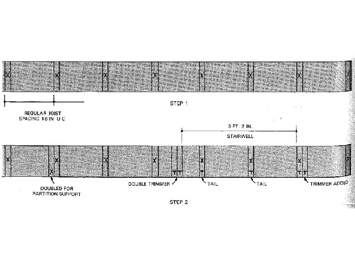
Laying out Joists • Note the direction the joists run. This can be found on the floor plan • The location of joists is usually laid out on the header joist but can be on the sill as well. • Experienced carpenters will not measure each joist location separately, they will make a master layout on a strip of wood called a rod.
Figure 8 -24 page 188 text
Figure 8 -25 page 188 text
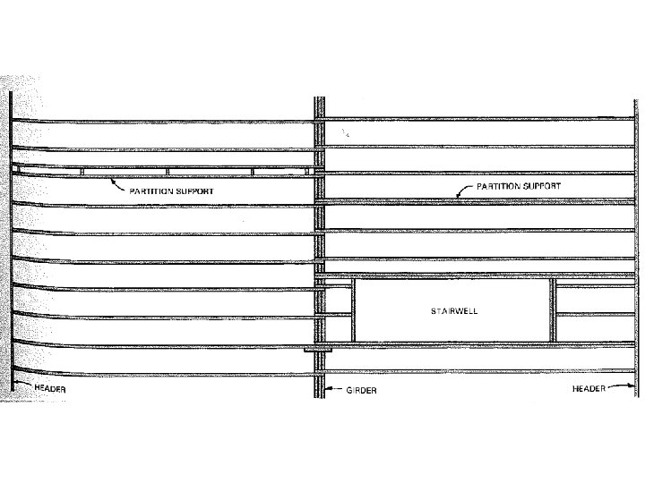
Laying out Joists • A corresponding must also be placed on the girder or load bearing wall in the center. • Partitions (walls) that run perpendicular to the floor joists double joists are required. • Also some extra framing members (joist) are required bath tubs, and any openings. This is due to the extra load in these areas.
Figure 8 -27 p 189 text
Installing Joists • Once the position of joists are determined and laid out the can be nailed in to the header joist using 3 ½” nails. • 3 nails per joist are used. • The carpenter must be sure to crown the joists. This refers to turning the slight crook or warpage up. • Joist are also toenailed to the sill and the girder or load bearing wall. Using 3” nails
Crowning Joists
Installing Joists Cont. • If joist butt they must be fastened together with a scarf or metal fastener. • If joists lap they must be nailed together. • Joists must not extend more than 4” beyond the girder or load bearing wall. This is to prevent the end of the joist from lifting the floor sheathing of the joist running from the other side of the building.
Video master 8 -4 p 116 resource
Framing Openings • To frame openings place sheathing across joists to provide a temporary work area. • Install inside trimmer joists first. This allows 3 ½ inch nails to penetrate deep in to the double header joists. • Now install the outside header joist. This allows 3 ½ inch nails to penetrate deep in to the tail joists.
Figure 8 -33 page 192 text
Framing Openings Cont. • Install the second header joists at this time and nail through the first trimmer joists to fasten it in place then fasten it to the outside header joist. • 8 -33 step 3 page 192 text
Framing Openings Cont. • Now the outside trimmer joists can be installed. It is fastened to the inside trimmer joist using 3” nails top and bottom every 12”. • Install 8 -33 step 4 page 192 text
Figure 8 -34 page 192 text
Blocking and Bridging • The purpose of blocking and bridging is to prevent the joist from twisting once the platform has been constructed. • It also transfers the load from one joist to another. This spreads the load on a joist over several joists. • Blocking is a solid piece of 2” material the same size as the joists nailed between two parallel joists. Also known as solid bridging.
Blocking and Bridging Cont. • Regular bridging also known as cross bridging can also be used. • It is made of 2”X 2” material and forms an X between two parallel joists. • Cross bridging may also be prefabricated from metal strips. • Metal cross bridging requires no nails making it easily installed.
Figure 8 -38 page 194 text
Fig 8 -40 page 194 text
Finishing • At this point the platform needs to be checked to ensure it has been completely nailed. • Now the subfloor can be installed. • The minimum building code requires 5/8 tong and grove plywood be used for subflooring. • Subflooring must be nailed 6” along the edges and every 12” in the field. • A construction adhesive must be installed on top of each floor joist before sheathing is installed.
Visual master 8 -9