Framing Transverse Framing Longitudinal Framing Composite framing Scantling


- Slides: 42
Framing
Transverse Framing
Longitudinal Framing
Composite framing
Scantling • In shipbuilding, the scantling refers to the collective dimensions of the various parts, particularly the framing and structural supports. The word is most often used in the plural to describe how much structural strength in the form of girders, I-beams, etc. is in a given section. The scantling length refers to the structural length of a ship.
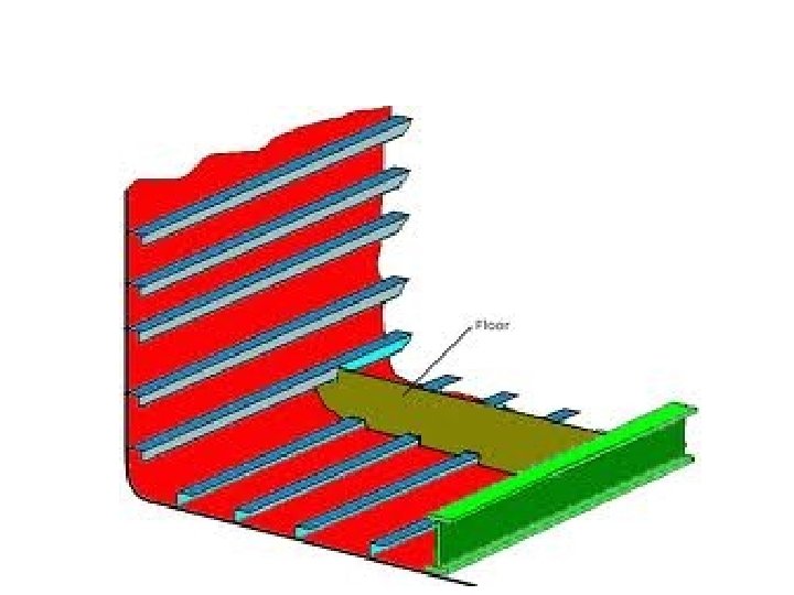
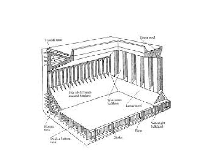
• The bottom shell may be transversely or longitudinally framed, longitudinal frames being preferred for ships exceeding 120 m length. The side shell framing may also be transversely or longitudinally framed, transverse framing being adopted in many conventional ships. A system of composite framing is usually found on large bulk carriers.
Beam Knees
Bracket
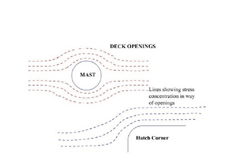
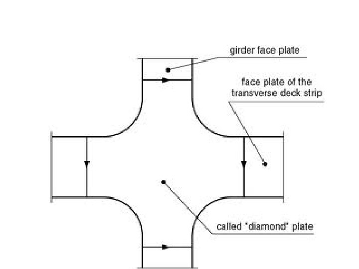
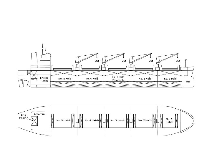
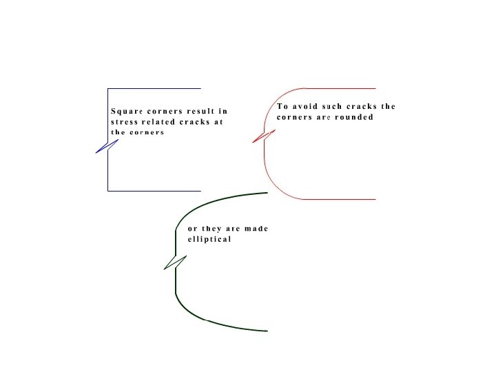
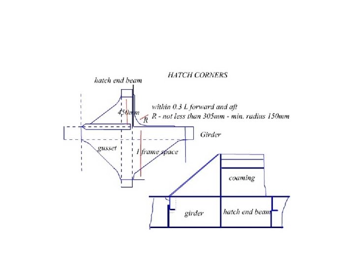
Strength continuity • Holes cut in the deck plating by way of hatchways, masts and others create areas of high local stress due to lack of continuity created by the opening. • Compensation around some of these openings may be overcome by increasing the sizes of the material used, buy a careful disposition of the material and by paying careful attention to the structural design.
Watertight Bulkhead
• Watertight bulkheads are vertically designed watertight divisions/walls within the ship’s structure, starting from ship’s double bottom top until the upper main deck. The bulkheads avoid ingress of water in a compartment if the adjacent compartment is flooded due to damage in ship’s hull, structure etc.
• The thickness of water tight bulkhead increases at the bottom as with increase in depth the pressure of the water increase. The horizontal plating thickness is gradually increased towards the bottom of the bulkhead. • Strengthening is increased by vertical plate bulb stiffeners or toe angle bar welded and spaced about 760 mm apart. The ends of bulkhead stiffeners are bracketed to the deck beams and tank top. The collision bulkheads are 12% thicker than other watertight bulkhead and stiffener spacing is reduced to 600 mm to give extra strength to sustain collision.
Collision Bulkhead
Corrugated Bulkhead
• The minimum number of water tight bulkhead depends upon the length of the ship and the location of its machinery space. All sea going merchant ships must have at least • Collision bulkhead placed at forward of the ship at 1/20 L (L is length of the ship) and it should be continuous to upper deck. (cont)
• One an aft peak bulkhead which protects and encloses the stern tube and rudder trunk of the ship • Two bulkheads enclosing the engine room from fore and aft if the location of the engine room is at mid ship. • If the engine room is located at the aft of the ship, the aft peak bulkhead forms the part of aft bulkhead of engine room. Hence only one bulkhead is required to be placed at fore part of the engine room, separating it from the cargo space
Function of bulkheads • Segregation of cargo, port wise and compatibility wise • Restricts flooding • Restricts spread of fire • Contributes to transverse and vertical strength.
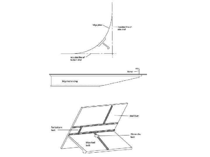
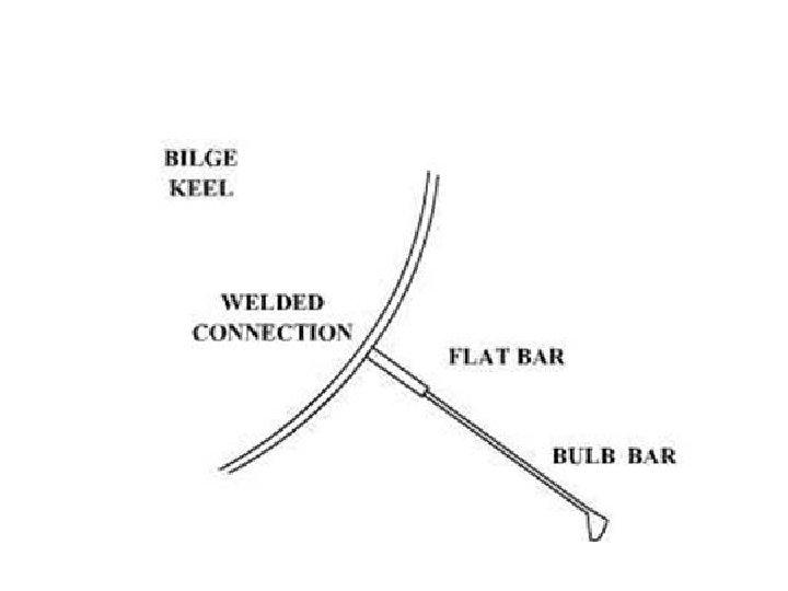
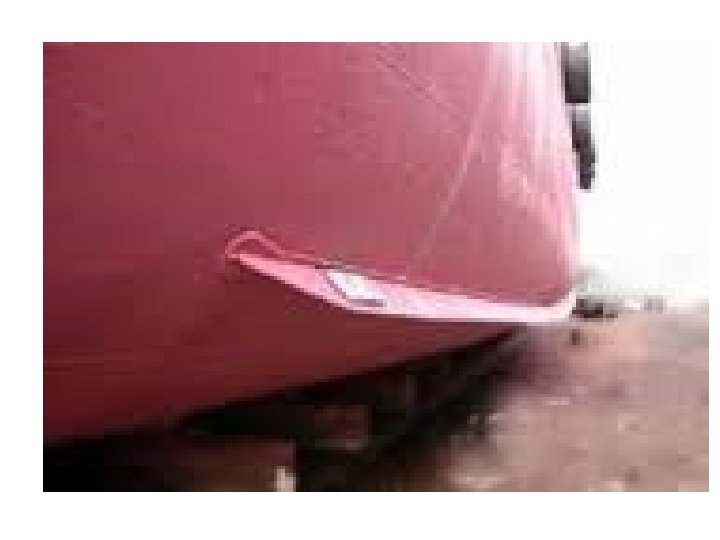
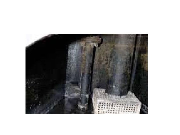
Bilge Keel • Runs along the bilge, on the outside, amidships , on either side. • Largely helps to reduce rolling in a seaway.
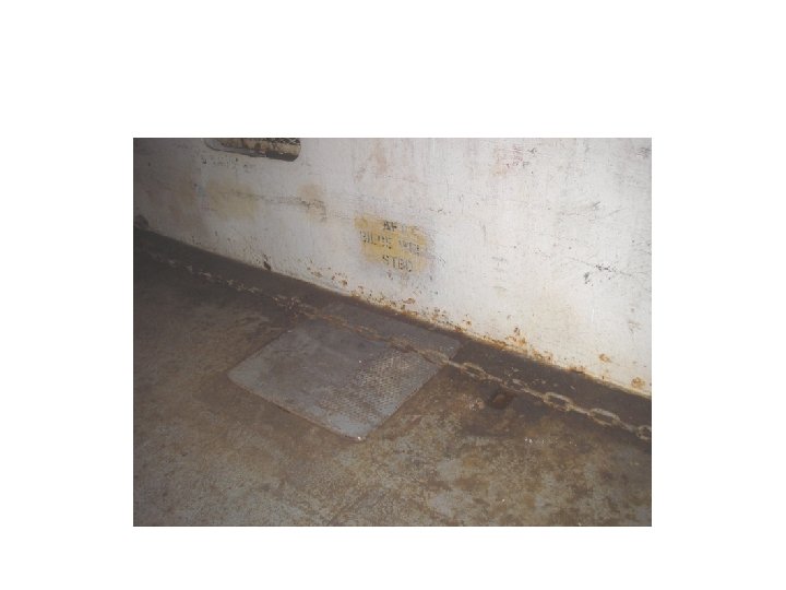
Bilges
Tanks
Deep Tank
Keels • At the centre line of the bottom structure is located the keel, often said to be the backbone of the ship. There are several types of keel (see section Bottom structure) • Bar Keel is made of thick steel, the depth being three to six times its width. Built up by joining sections 10 to 20 metres long, joined by vertical scarphs which have a length nine times the thickness of the plate.
• Flat Plate keel: May have a width of from 1 to 2 metres. It must be of full thickness for threefifths of the ships length amidships but may be gradually reduced towards the ends. • Duct Keel: A form of flat plate keel but having two centre girders running longitudinally, often between the Engine room forward bulkhead and collision bulkhead. It provides a strong box girder with the advantage of being able to run pipelines and associated remote operated valves from the tanks.
Keels
Plate Keel
Duct Keel