ECE 271 Electronic Circuits I Topic 6 Analog
- Slides: 184
ECE 271 Electronic Circuits I Topic 6 Analog Circuits Ideal Operational Amplifiers One Transistor Amplifier NJIT ECE 271 Dr. Serhiy Levkov Topic 6 - 1
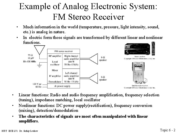
Example of Analog Electronic System: FM Stereo Receiver • • • Much information in the world (temperature, pressure, light intensity, sound, etc. ) is analog in nature. In electric form those signals are transformed by different linear and nonlinear functions. Linear functions: Radio and audio frequency amplification, frequency selection (tuning), impedance matching, local oscillator Nonlinear functions: DC power supply(rectification), frequency conversion (mixing), detection/demodulation The characteristics of signals are most often manipulated with linear amplifiers. NJIT ECE 271 Dr. Serhiy Levkov Topic 6 - 2
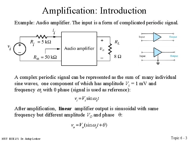
Amplification: Introduction Example: Audio amplifier. The input is a form of complicated periodic signal. A complex periodic signal can be represented as the sum of many individual sine waves, one component of which has amplitude Vi = 1 m. V and frequency ws with 0 phase (signal is used as reference): After amplification, linear amplifier output is sinusoidal with same frequency but different amplitude VO and phase : NJIT ECE 271 Dr. Serhiy Levkov Topic 6 - 3
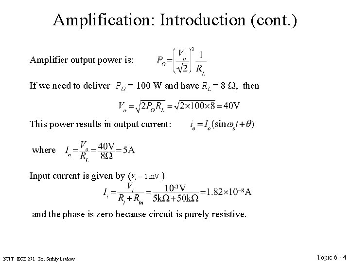
Amplification: Introduction (cont. ) Amplifier output power is: If we need to deliver PO = 100 W and have RL = 8 W, then This power results in output current: where Input current is given by (Vi = 1 m. V ) and the phase is zero because circuit is purely resistive. NJIT ECE 271 Dr. Serhiy Levkov Topic 6 - 4
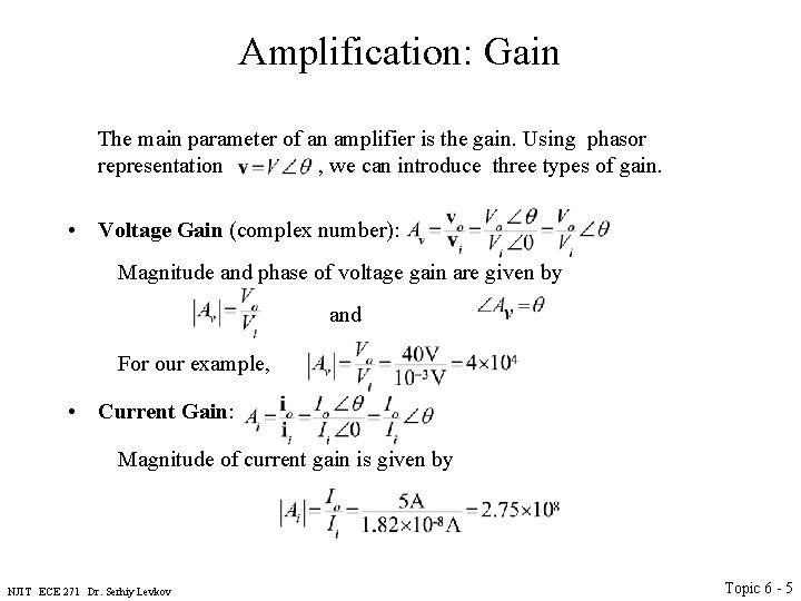
Amplification: Gain The main parameter of an amplifier is the gain. Using phasor representation , we can introduce three types of gain. • Voltage Gain (complex number): Magnitude and phase of voltage gain are given by and For our example, • Current Gain: Magnitude of current gain is given by NJIT ECE 271 Dr. Serhiy Levkov Topic 6 - 5
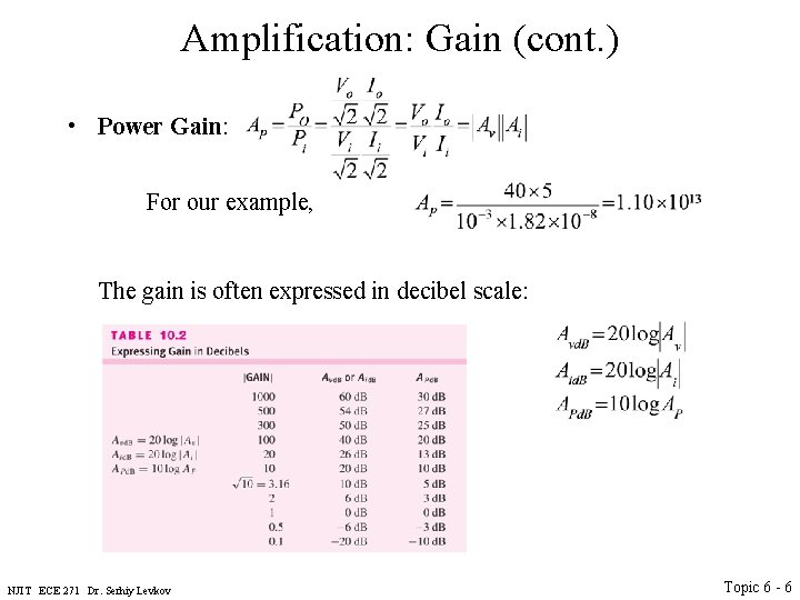
Amplification: Gain (cont. ) • Power Gain: For our example, The gain is often expressed in decibel scale: NJIT ECE 271 Dr. Serhiy Levkov Topic 6 - 6
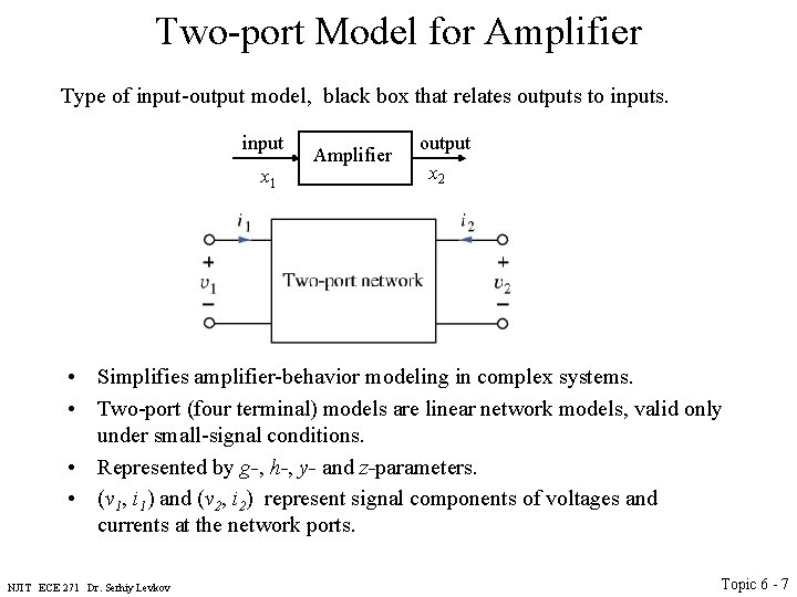
Two-port Model for Amplifier Type of input-output model, black box that relates outputs to inputs. input x 1 Amplifier output x 2 • Simplifies amplifier-behavior modeling in complex systems. • Two-port (four terminal) models are linear network models, valid only under small-signal conditions. • Represented by g-, h-, y- and z-parameters. • (v 1, i 1) and (v 2, i 2) represent signal components of voltages and currents at the network ports. NJIT ECE 271 Dr. Serhiy Levkov Topic 6 - 7
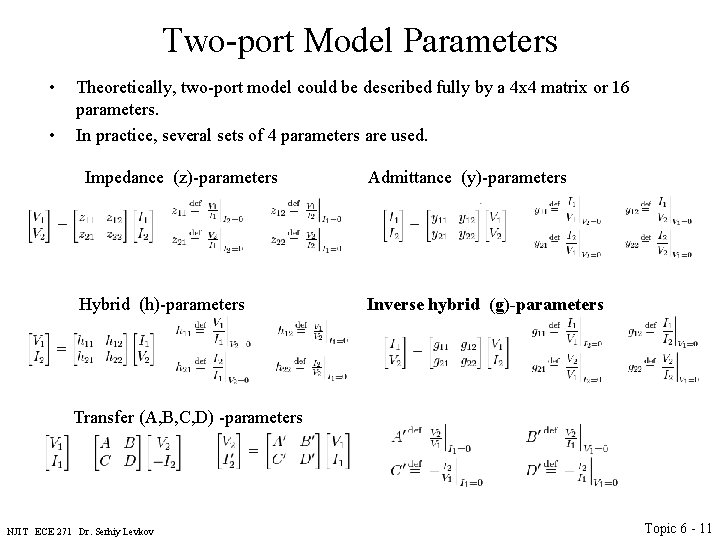
Two-port Model Parameters • • Theoretically, two-port model could be described fully by a 4 x 4 matrix or 16 parameters. In practice, several sets of 4 parameters are used. NJIT ECE 271 Dr. Serhiy Levkov Topic 6 - 8
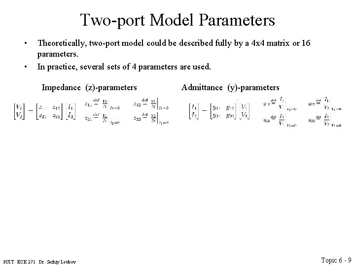
Two-port Model Parameters • • Theoretically, two-port model could be described fully by a 4 x 4 matrix or 16 parameters. In practice, several sets of 4 parameters are used. Impedance (z)-parameters Admittance (y)-parameters NJIT ECE 271 Dr. Serhiy Levkov Topic 6 - 9
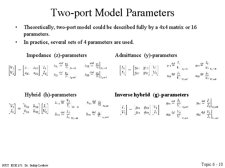
Two-port Model Parameters • • Theoretically, two-port model could be described fully by a 4 x 4 matrix or 16 parameters. In practice, several sets of 4 parameters are used. Impedance (z)-parameters Admittance (y)-parameters Hybrid (h)-parameters Inverse hybrid (g)-parameters NJIT ECE 271 Dr. Serhiy Levkov Topic 6 - 10
Two-port Model Parameters • • Theoretically, two-port model could be described fully by a 4 x 4 matrix or 16 parameters. In practice, several sets of 4 parameters are used. Impedance (z)-parameters Admittance (y)-parameters Hybrid (h)-parameters Inverse hybrid (g)-parameters Transfer (A, B, C, D) -parameters NJIT ECE 271 Dr. Serhiy Levkov Topic 6 - 11
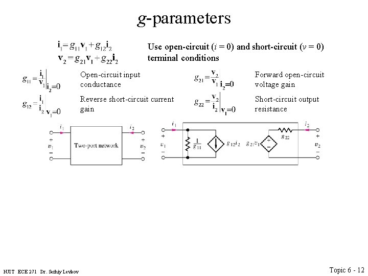
g-parameters Use open-circuit (i = 0) and short-circuit (v = 0) terminal conditions NJIT ECE 271 Dr. Serhiy Levkov Open-circuit input conductance Forward open-circuit voltage gain Reverse short-circuit current gain Short-circuit output resistance Topic 6 - 12
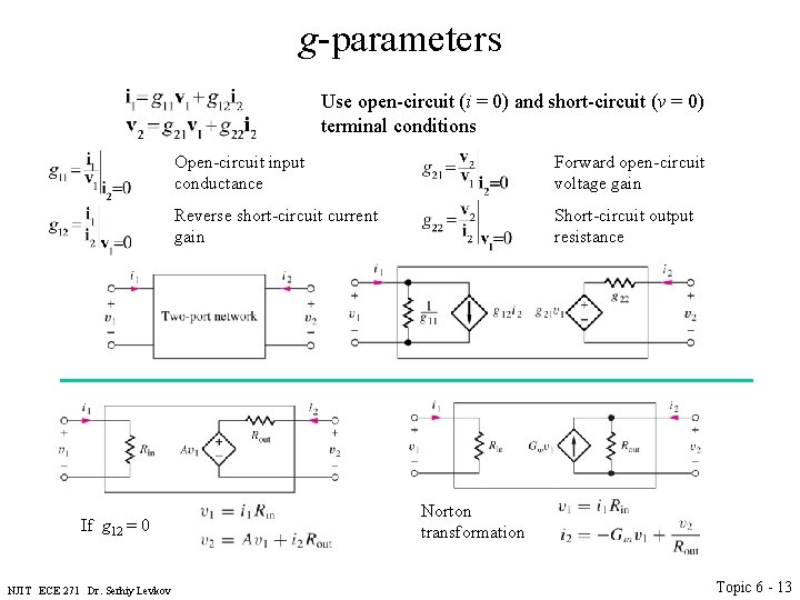
g-parameters Use open-circuit (i = 0) and short-circuit (v = 0) terminal conditions If g 12 = 0 NJIT ECE 271 Dr. Serhiy Levkov Open-circuit input conductance Forward open-circuit voltage gain Reverse short-circuit current gain Short-circuit output resistance Norton transformation Topic 6 - 13
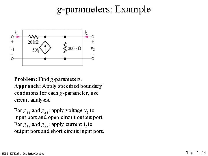
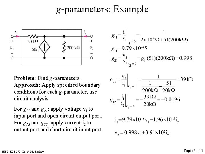
g-parameters: Example Problem: Find g-parameters. Approach: Apply specified boundary conditions for each g-parameter, use circuit analysis. For g 11 and g 21: apply voltage v 1 to input port and open circuit output port. For g 12 and g 22: apply current i 2 to output port and short circuit input port. NJIT ECE 271 Dr. Serhiy Levkov Topic 6 - 14
g-parameters: Example Problem: Find g-parameters. Approach: Apply specified boundary conditions for each g-parameter, use circuit analysis. For g 11 and g 21: apply voltage v 1 to input port and open circuit output port. For g 12 and g 22: apply current i 2 to output port and short circuit input port. NJIT ECE 271 Dr. Serhiy Levkov Topic 6 - 15
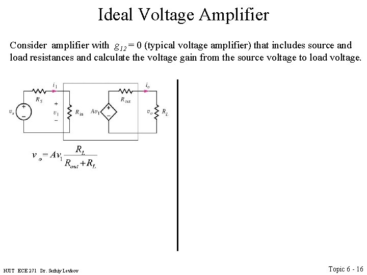
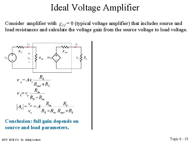
Ideal Voltage Amplifier Consider amplifier with g 12 = 0 (typical voltage amplifier) that includes source and load resistances and calculate the voltage gain from the source voltage to load voltage. NJIT ECE 271 Dr. Serhiy Levkov Topic 6 - 16
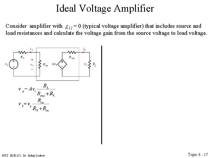
Ideal Voltage Amplifier Consider amplifier with g 12 = 0 (typical voltage amplifier) that includes source and load resistances and calculate the voltage gain from the source voltage to load voltage. NJIT ECE 271 Dr. Serhiy Levkov Topic 6 - 17
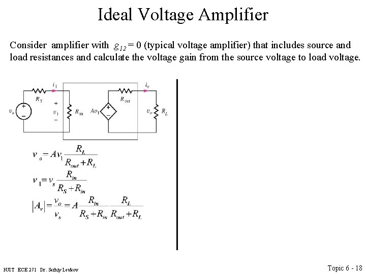
Ideal Voltage Amplifier Consider amplifier with g 12 = 0 (typical voltage amplifier) that includes source and load resistances and calculate the voltage gain from the source voltage to load voltage. NJIT ECE 271 Dr. Serhiy Levkov Topic 6 - 18
Ideal Voltage Amplifier Consider amplifier with g 12 = 0 (typical voltage amplifier) that includes source and load resistances and calculate the voltage gain from the source voltage to load voltage. Conclusion: full gain depends on source and load parameters. NJIT ECE 271 Dr. Serhiy Levkov Topic 6 - 19
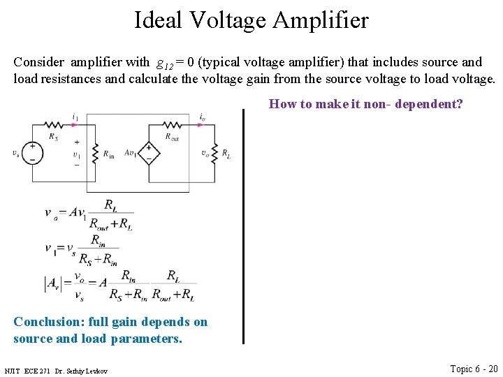
Ideal Voltage Amplifier Consider amplifier with g 12 = 0 (typical voltage amplifier) that includes source and load resistances and calculate the voltage gain from the source voltage to load voltage. How to make it non- dependent? Conclusion: full gain depends on source and load parameters. NJIT ECE 271 Dr. Serhiy Levkov Topic 6 - 20
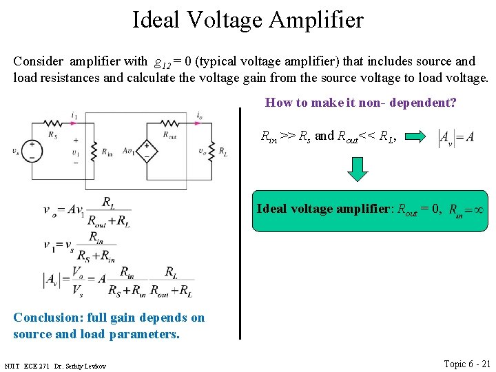
Ideal Voltage Amplifier Consider amplifier with g 12 = 0 (typical voltage amplifier) that includes source and load resistances and calculate the voltage gain from the source voltage to load voltage. How to make it non- dependent? Rin >> Rs and Rout<< RL, Ideal voltage amplifier: Rout = 0, Conclusion: full gain depends on source and load parameters. NJIT ECE 271 Dr. Serhiy Levkov Topic 6 - 21
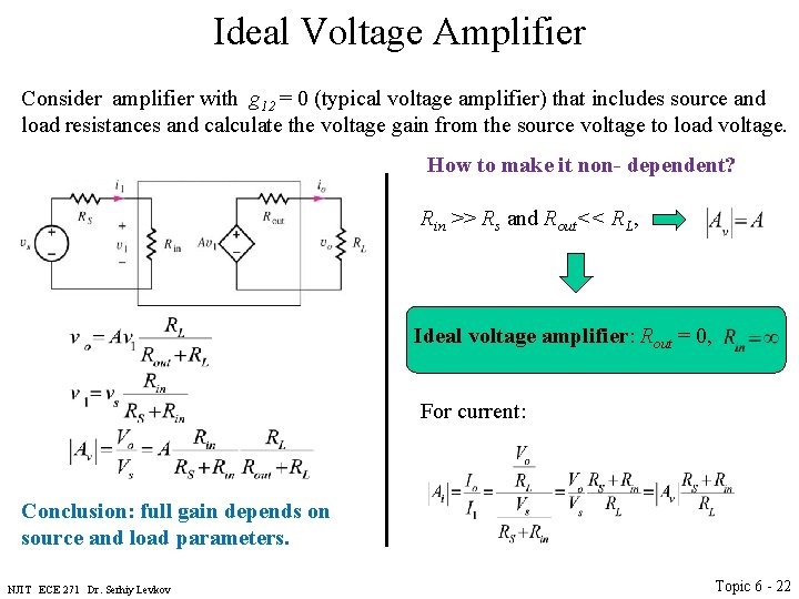
Ideal Voltage Amplifier Consider amplifier with g 12 = 0 (typical voltage amplifier) that includes source and load resistances and calculate the voltage gain from the source voltage to load voltage. How to make it non- dependent? Rin >> Rs and Rout<< RL, Ideal voltage amplifier: Rout = 0, For current: Conclusion: full gain depends on source and load parameters. NJIT ECE 271 Dr. Serhiy Levkov Topic 6 - 22
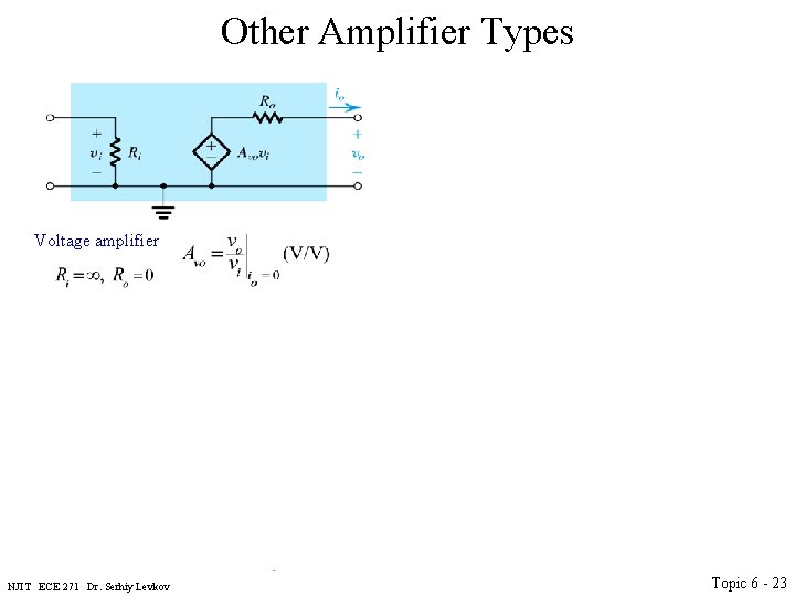
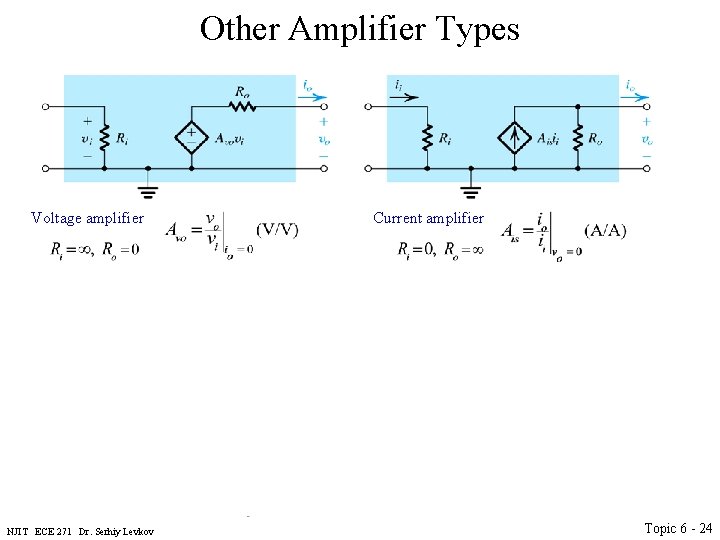
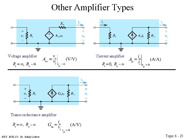
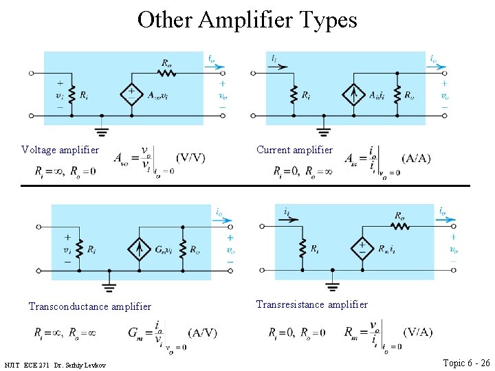
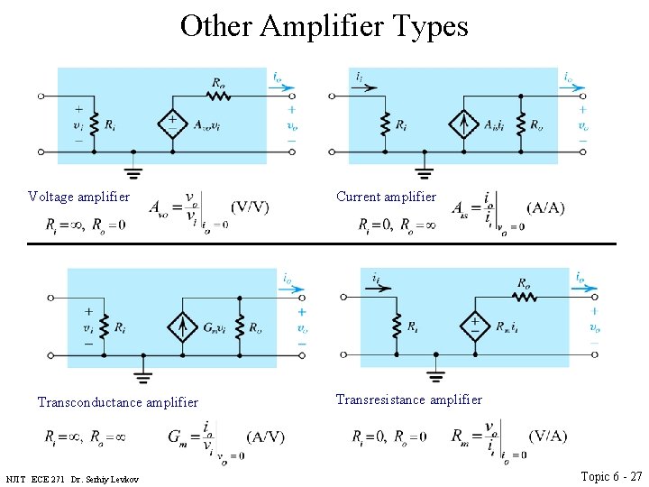
Other Amplifier Types Voltage amplifier Transconductance amplifier NJIT ECE 271 Dr. Serhiy Levkov Current amplifier Transresistance amplifier Topic 6 - 23
Other Amplifier Types Voltage amplifier Transconductance amplifier NJIT ECE 271 Dr. Serhiy Levkov Current amplifier Transresistance amplifier Topic 6 - 24
Other Amplifier Types Voltage amplifier Transconductance amplifier NJIT ECE 271 Dr. Serhiy Levkov Current amplifier Transresistance amplifier Topic 6 - 25
Other Amplifier Types Voltage amplifier Transconductance amplifier NJIT ECE 271 Dr. Serhiy Levkov Current amplifier Transresistance amplifier Topic 6 - 26
Other Amplifier Types Voltage amplifier Transconductance amplifier NJIT ECE 271 Dr. Serhiy Levkov Current amplifier Transresistance amplifier Topic 6 - 27
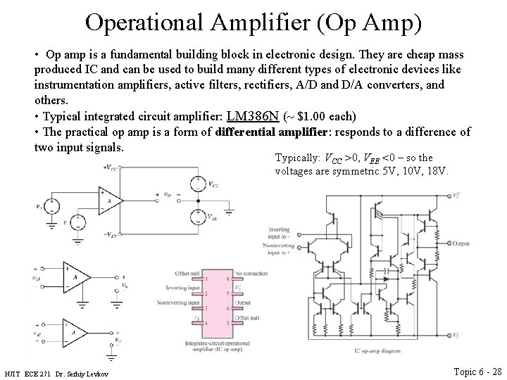
Operational Amplifier (Op Amp) • Op amp is a fundamental building block in electronic design. They are cheap mass produced IC and can be used to build many different types of electronic devices like instrumentation amplifiers, active filters, rectifiers, A/D and D/A converters, and others. • Typical integrated circuit amplifier: LM 386 N (~ $1. 00 each) • The practical op amp is a form of differential amplifier: responds to a difference of two input signals. Typically: VCC >0, VEE <0 – so the voltages are symmetric 5 V, 10 V, 18 V. NJIT ECE 271 Dr. Serhiy Levkov Topic 6 - 28
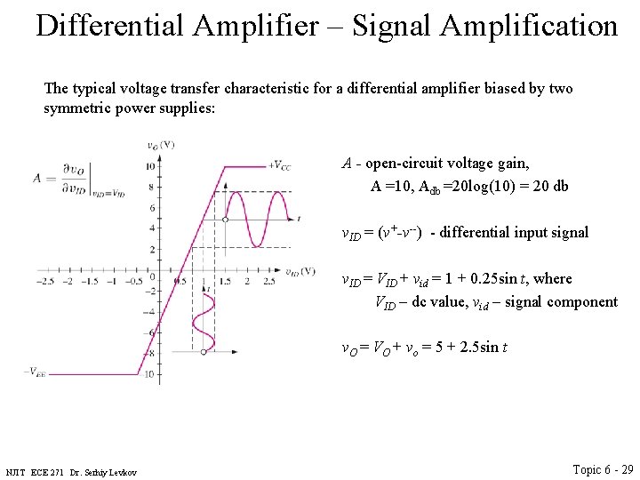
Differential Amplifier – Signal Amplification The typical voltage transfer characteristic for a differential amplifier biased by two symmetric power supplies: A - open-circuit voltage gain, A =10, Adb =20 log(10) = 20 db v. ID = (v+-v--) - differential input signal v. ID = VID + vid = 1 + 0. 25 sin t, where VID – dc value, vid – signal component v. O = VO + vo = 5 + 2. 5 sin t NJIT ECE 271 Dr. Serhiy Levkov Topic 6 - 29
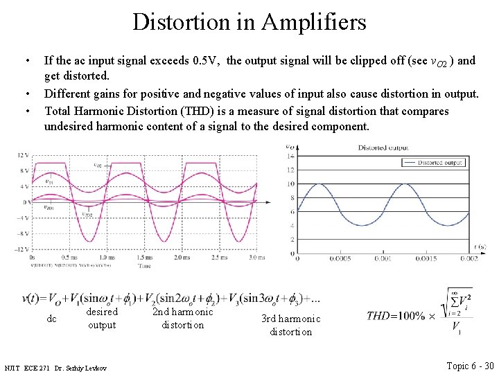
Distortion in Amplifiers • • • If the ac input signal exceeds 0. 5 V, the output signal will be clipped off (see v. O 2 ) and get distorted. Different gains for positive and negative values of input also cause distortion in output. Total Harmonic Distortion (THD) is a measure of signal distortion that compares undesired harmonic content of a signal to the desired component. dc desired output NJIT ECE 271 Dr. Serhiy Levkov 2 nd harmonic distortion 3 rd harmonic distortion Topic 6 - 30
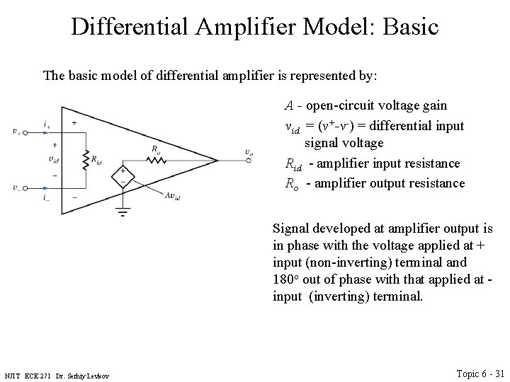
Differential Amplifier Model: Basic The basic model of differential amplifier is represented by: A - open-circuit voltage gain vid = (v+-v-) = differential input signal voltage Rid - amplifier input resistance Ro - amplifier output resistance Signal developed at amplifier output is in phase with the voltage applied at + input (non-inverting) terminal and 180 o out of phase with that applied at - input (inverting) terminal. NJIT ECE 271 Dr. Serhiy Levkov Topic 6 - 31
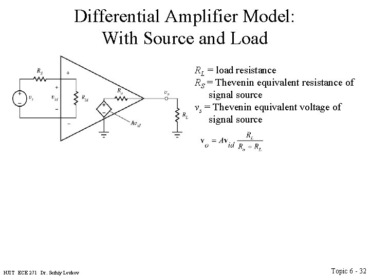
Differential Amplifier Model: With Source and Load RL = load resistance RS = Thevenin equivalent resistance of signal source vs = Thevenin equivalent voltage of signal source NJIT ECE 271 Dr. Serhiy Levkov Topic 6 - 32
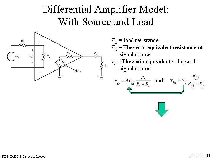
Differential Amplifier Model: With Source and Load RL = load resistance RS = Thevenin equivalent resistance of signal source vs = Thevenin equivalent voltage of signal source and NJIT ECE 271 Dr. Serhiy Levkov Topic 6 - 33
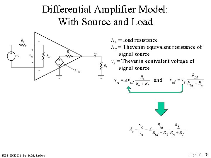
Differential Amplifier Model: With Source and Load RL = load resistance RS = Thevenin equivalent resistance of signal source vs = Thevenin equivalent voltage of signal source and NJIT ECE 271 Dr. Serhiy Levkov Topic 6 - 34
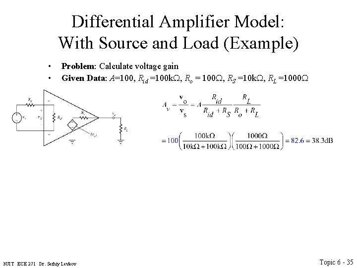
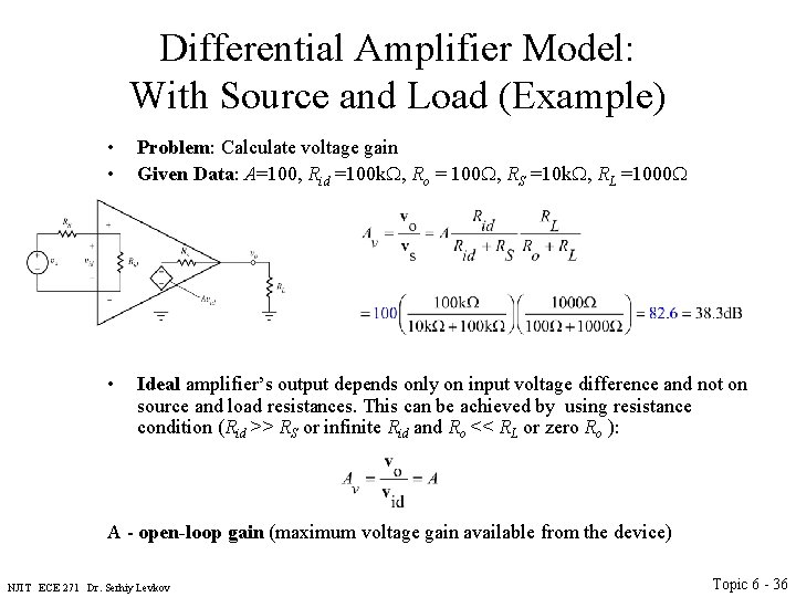
Differential Amplifier Model: With Source and Load (Example) • • Problem: Calculate voltage gain Given Data: A=100, Rid =100 k. W, Ro = 100 W, RS =10 k. W, RL =1000 W NJIT ECE 271 Dr. Serhiy Levkov Topic 6 - 35
Differential Amplifier Model: With Source and Load (Example) • • Problem: Calculate voltage gain Given Data: A=100, Rid =100 k. W, Ro = 100 W, RS =10 k. W, RL =1000 W • Ideal amplifier’s output depends only on input voltage difference and not on source and load resistances. This can be achieved by using resistance condition (Rid >> RS or infinite Rid and Ro << RL or zero Ro ): A - open-loop gain (maximum voltage gain available from the device) NJIT ECE 271 Dr. Serhiy Levkov Topic 6 - 36
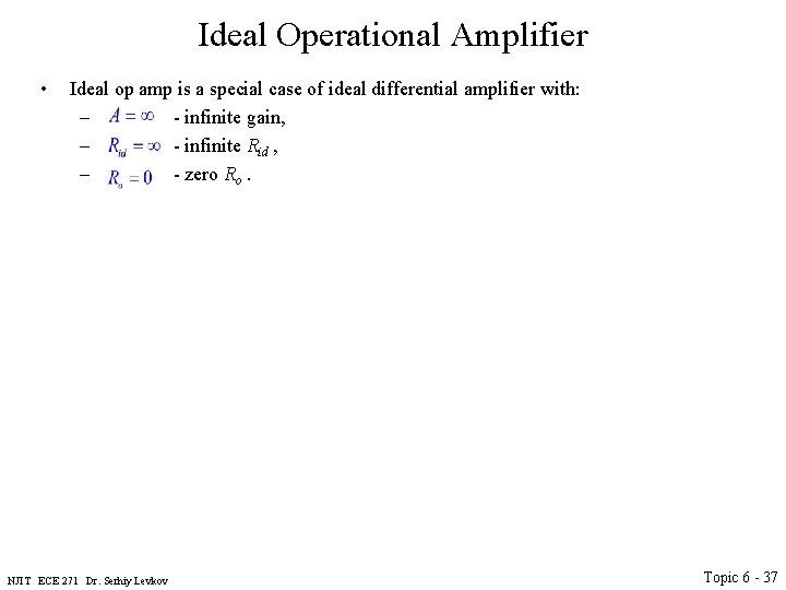
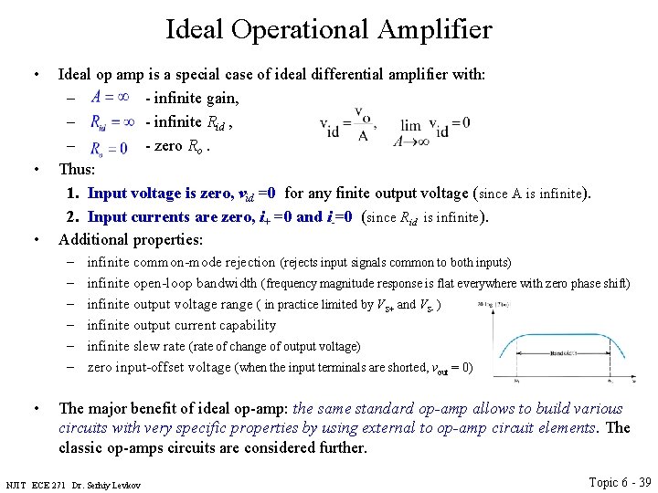
Ideal Operational Amplifier • Ideal op amp is a special case of ideal differential amplifier with: – - infinite gain, – - infinite Rid , – - zero Ro. NJIT ECE 271 Dr. Serhiy Levkov Topic 6 - 37
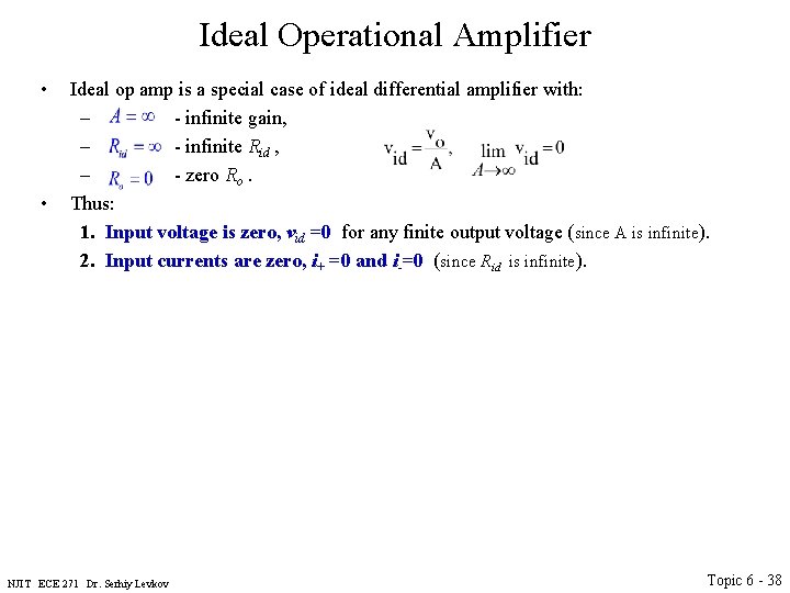
Ideal Operational Amplifier • • Ideal op amp is a special case of ideal differential amplifier with: – - infinite gain, – - infinite Rid , – - zero Ro. Thus: 1. Input voltage is zero, vid =0 for any finite output voltage (since A is infinite). 2. Input currents are zero, i+ =0 and i-=0 (since Rid is infinite). NJIT ECE 271 Dr. Serhiy Levkov Topic 6 - 38
Ideal Operational Amplifier • • • Ideal op amp is a special case of ideal differential amplifier with: – - infinite gain, – - infinite Rid , – - zero Ro. Thus: 1. Input voltage is zero, vid =0 for any finite output voltage (since A is infinite). 2. Input currents are zero, i+ =0 and i-=0 (since Rid is infinite). Additional properties: – – – • infinite common-mode rejection (rejects input signals common to both inputs) infinite open-loop bandwidth (frequency magnitude response is flat everywhere with zero phase shift) infinite output voltage range ( in practice limited by VS+ and VS- ) infinite output current capability infinite slew rate (rate of change of output voltage) zero input-offset voltage (when the input terminals are shorted, vout = 0) The major benefit of ideal op-amp: the same standard op-amp allows to build various circuits with very specific properties by using external to op-amp circuit elements. The classic op-amps circuits are considered further. NJIT ECE 271 Dr. Serhiy Levkov Topic 6 - 39
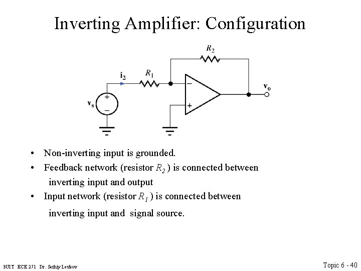
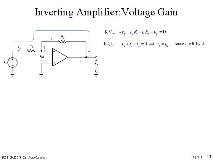
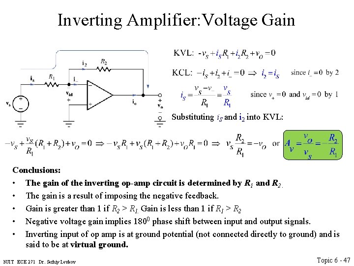
Inverting Amplifier: Configuration • Non-inverting input is grounded. • Feedback network (resistor R 2 ) is connected between inverting input and output • Input network (resistor R 1 ) is connected between inverting input and signal source. NJIT ECE 271 Dr. Serhiy Levkov Topic 6 - 40
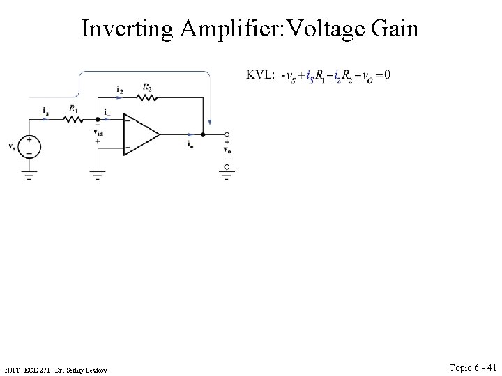
Inverting Amplifier: Voltage Gain NJIT ECE 271 Dr. Serhiy Levkov Topic 6 - 41
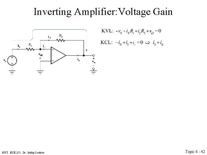
Inverting Amplifier: Voltage Gain NJIT ECE 271 Dr. Serhiy Levkov Topic 6 - 42
Inverting Amplifier: Voltage Gain NJIT ECE 271 Dr. Serhiy Levkov Topic 6 - 43
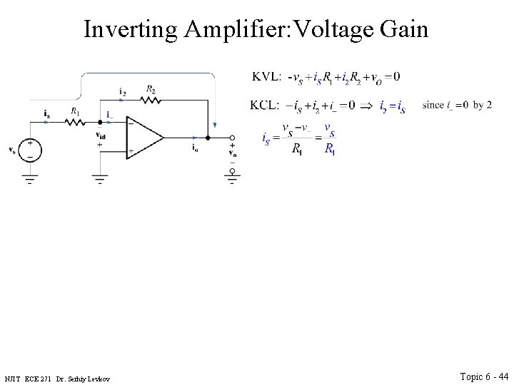
Inverting Amplifier: Voltage Gain NJIT ECE 271 Dr. Serhiy Levkov Topic 6 - 44
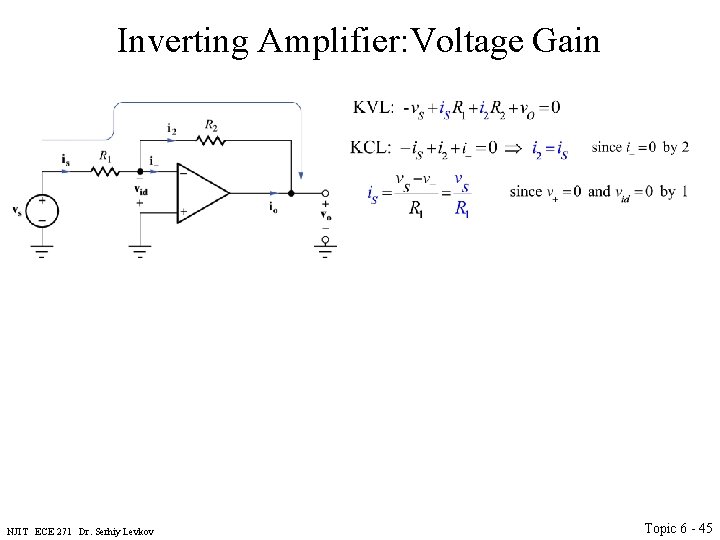
Inverting Amplifier: Voltage Gain NJIT ECE 271 Dr. Serhiy Levkov Topic 6 - 45
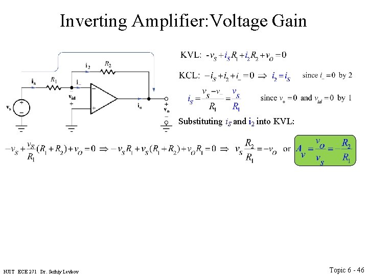
Inverting Amplifier: Voltage Gain Substituting i. S and i 2 into KVL: NJIT ECE 271 Dr. Serhiy Levkov Topic 6 - 46
Inverting Amplifier: Voltage Gain Substituting i. S and i 2 into KVL: Conclusions: • The gain of the inverting op-amp circuit is determined by R 1 and R 2. • The gain is a result of imposing the negative feedback. • Gain is greater than 1 if R 2 > R 1. Gain is less than 1 if R 1 > R 2 • Negative voltage gain implies 1800 phase shift between input and output signals. • Inverting input of op amp is at ground potential (not connected directly to ground) and is said to be at virtual ground. NJIT ECE 271 Dr. Serhiy Levkov Topic 6 - 47
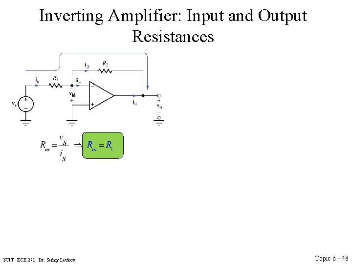
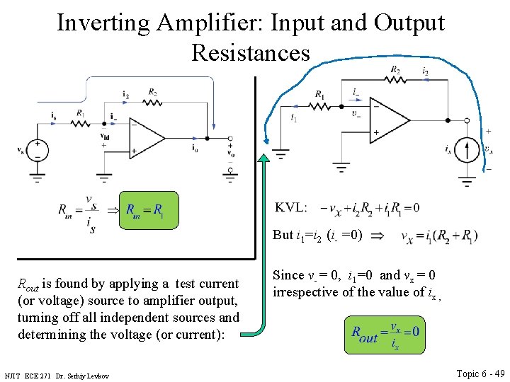
Inverting Amplifier: Input and Output Resistances NJIT ECE 271 Dr. Serhiy Levkov Topic 6 - 48
Inverting Amplifier: Input and Output Resistances But i 1=i 2 (i- =0) Rout is found by applying a test current (or voltage) source to amplifier output, turning off all independent sources and determining the voltage (or current): NJIT ECE 271 Dr. Serhiy Levkov Since v- = 0, i 1=0 and vx = 0 irrespective of the value of ix , Topic 6 - 49
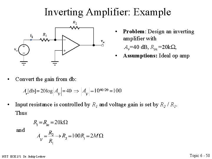
Inverting Amplifier: Example • Problem: Design an inverting amplifier with Av=40 d. B, Rin =20 k. W, • Assumptions: Ideal op amp • Convert the gain from db: • Input resistance is controlled by R 1 and voltage gain is set by R 2 / R 1. Thus and NJIT ECE 271 Dr. Serhiy Levkov Topic 6 - 50
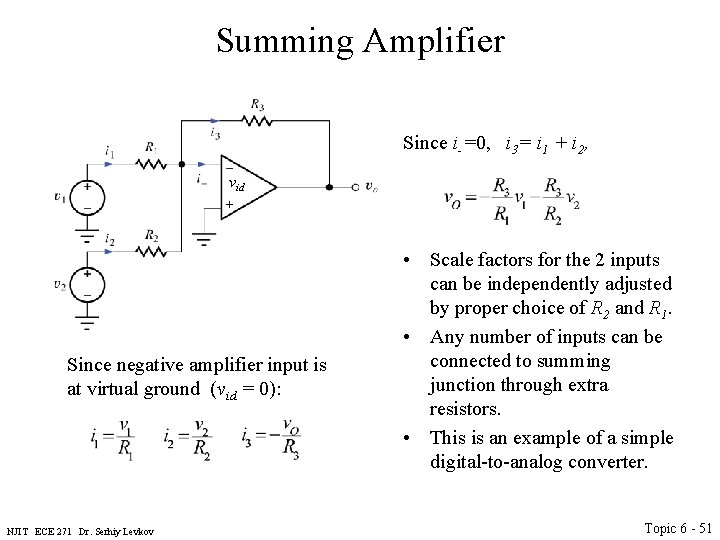
Summing Amplifier Since i-=0, i 3= i 1 + i 2, vid Since negative amplifier input is at virtual ground (vid = 0): NJIT ECE 271 Dr. Serhiy Levkov • Scale factors for the 2 inputs can be independently adjusted by proper choice of R 2 and R 1. • Any number of inputs can be connected to summing junction through extra resistors. • This is an example of a simple digital-to-analog converter. Topic 6 - 51
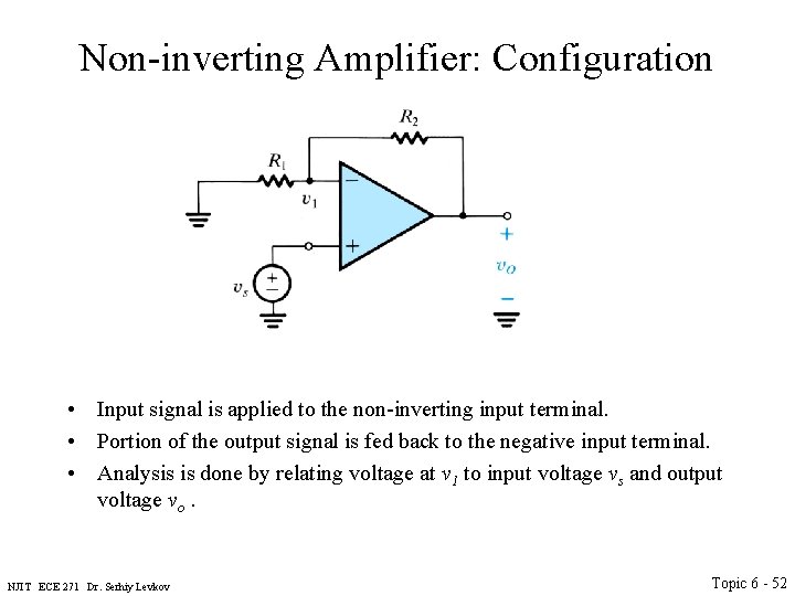
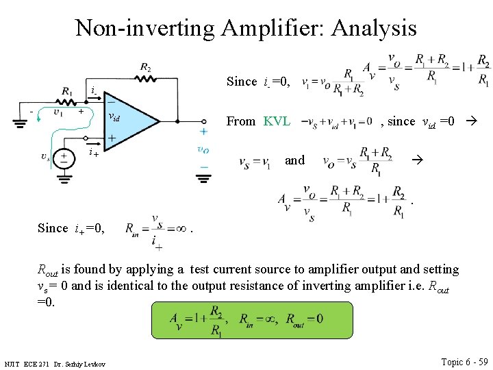
Non-inverting Amplifier: Configuration • Input signal is applied to the non-inverting input terminal. • Portion of the output signal is fed back to the negative input terminal. • Analysis is done by relating voltage at v 1 to input voltage vs and output voltage vo. NJIT ECE 271 Dr. Serhiy Levkov Topic 6 - 52
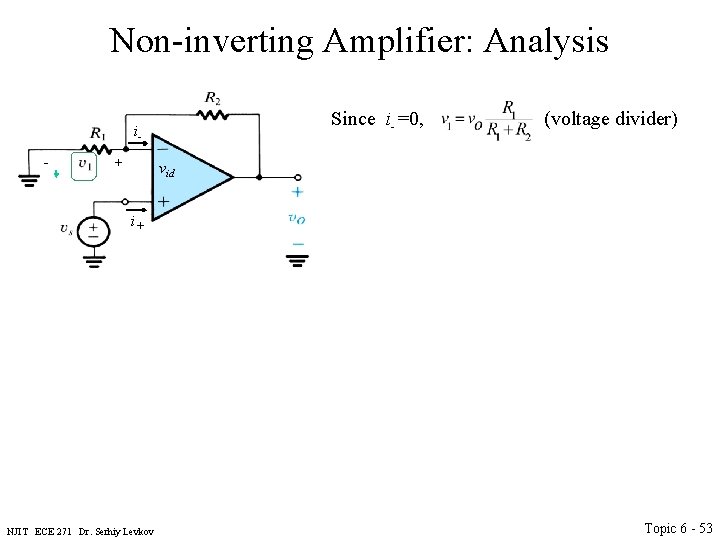
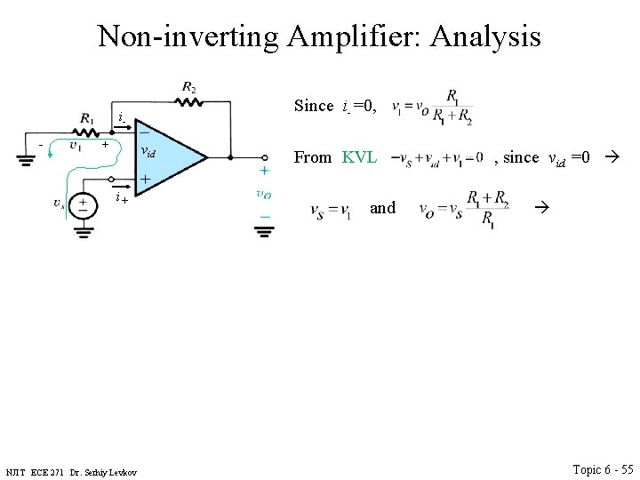
Non-inverting Amplifier: Analysis Since i-=0, (voltage divider) i- + vid i+ NJIT ECE 271 Dr. Serhiy Levkov Topic 6 - 53
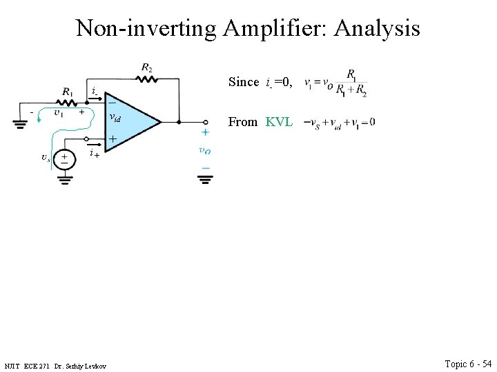
Non-inverting Amplifier: Analysis Since i-=0, i- + vid i+ NJIT ECE 271 Dr. Serhiy Levkov From KVL Topic 6 - 54
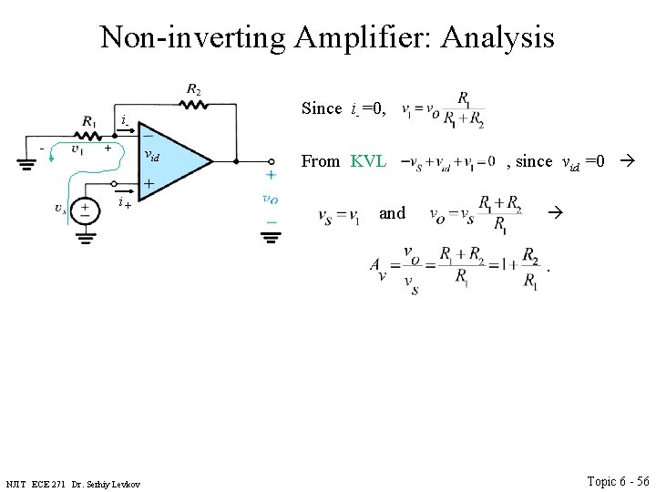
Non-inverting Amplifier: Analysis Since i-=0, i- + vid i+ NJIT ECE 271 Dr. Serhiy Levkov From KVL , since vid =0 and Topic 6 - 55
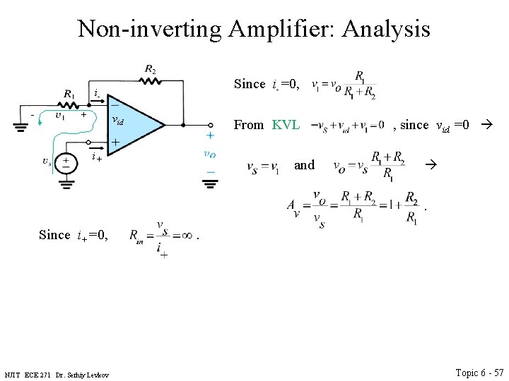
Non-inverting Amplifier: Analysis Since i-=0, i- + vid i+ From KVL , since vid =0 and . NJIT ECE 271 Dr. Serhiy Levkov Topic 6 - 56
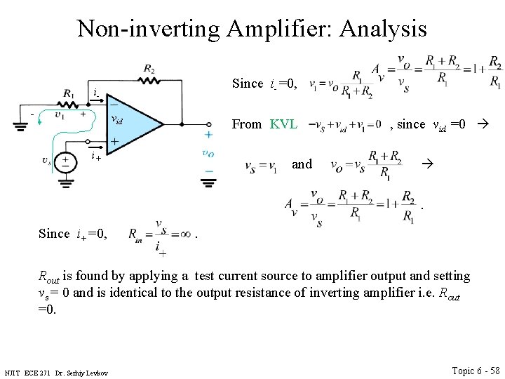
Non-inverting Amplifier: Analysis Since i-=0, i- + vid i+ From KVL , since vid =0 and . Since i+=0, . NJIT ECE 271 Dr. Serhiy Levkov Topic 6 - 57
Non-inverting Amplifier: Analysis Since i-=0, i- + vid i+ From KVL , since vid =0 and . Since i+=0, . Rout is found by applying a test current source to amplifier output and setting vs = 0 and is identical to the output resistance of inverting amplifier i. e. Rout =0. NJIT ECE 271 Dr. Serhiy Levkov Topic 6 - 58
Non-inverting Amplifier: Analysis Since i-=0, i- + vid i+ From KVL , since vid =0 and . Since i+=0, . Rout is found by applying a test current source to amplifier output and setting vs = 0 and is identical to the output resistance of inverting amplifier i. e. Rout =0. NJIT ECE 271 Dr. Serhiy Levkov Topic 6 - 59
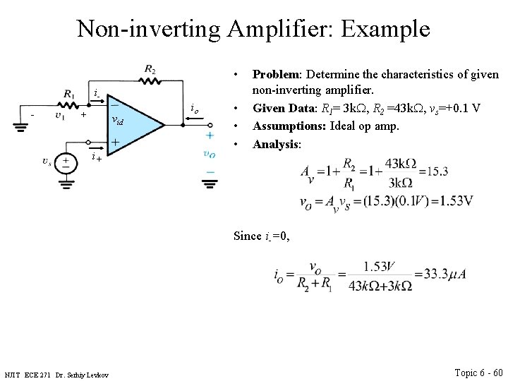
Non-inverting Amplifier: Example • i- + vid i+ io • • • Problem: Determine the characteristics of given non-inverting amplifier. Given Data: R 1= 3 k. W, R 2 =43 k. W, vs=+0. 1 V Assumptions: Ideal op amp. Analysis: Since i-=0, NJIT ECE 271 Dr. Serhiy Levkov Topic 6 - 60
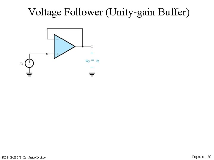
Voltage Follower (Unity-gain Buffer) NJIT ECE 271 Dr. Serhiy Levkov Topic 6 - 61
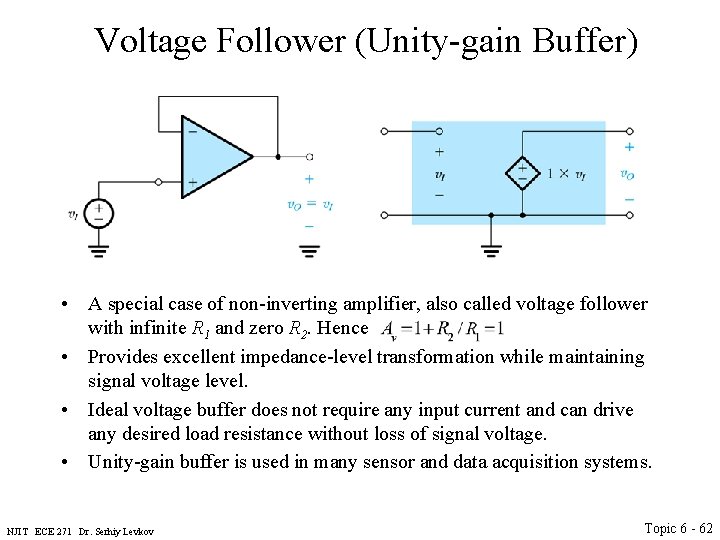
Voltage Follower (Unity-gain Buffer) • A special case of non-inverting amplifier, also called voltage follower with infinite R 1 and zero R 2. Hence • Provides excellent impedance-level transformation while maintaining signal voltage level. • Ideal voltage buffer does not require any input current and can drive any desired load resistance without loss of signal voltage. • Unity-gain buffer is used in many sensor and data acquisition systems. NJIT ECE 271 Dr. Serhiy Levkov Topic 6 - 62
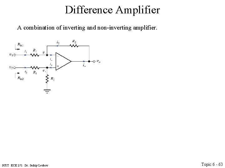
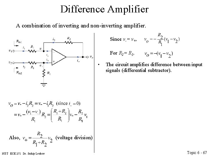
Difference Amplifier A combination of inverting and non-inverting amplifier. NJIT ECE 271 Dr. Serhiy Levkov Topic 6 - 63
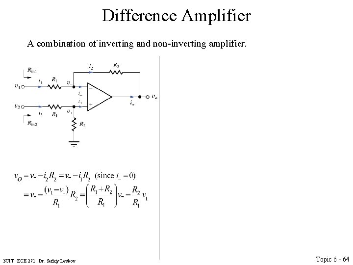
Difference Amplifier A combination of inverting and non-inverting amplifier. NJIT ECE 271 Dr. Serhiy Levkov Topic 6 - 64
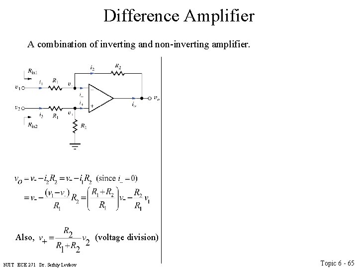
Difference Amplifier A combination of inverting and non-inverting amplifier. Also, (voltage division) NJIT ECE 271 Dr. Serhiy Levkov Topic 6 - 65
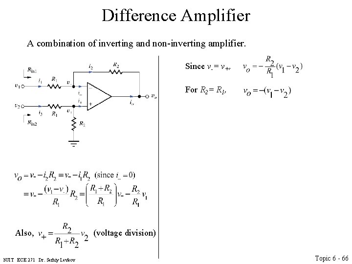
Difference Amplifier A combination of inverting and non-inverting amplifier. Since v-= v+, For R 2= R 1, Also, (voltage division) NJIT ECE 271 Dr. Serhiy Levkov Topic 6 - 66
Difference Amplifier A combination of inverting and non-inverting amplifier. Since v-= v+, For R 2= R 1, • The circuit amplifies difference between input signals (differential subtractor). Also, (voltage division) NJIT ECE 271 Dr. Serhiy Levkov Topic 6 - 67
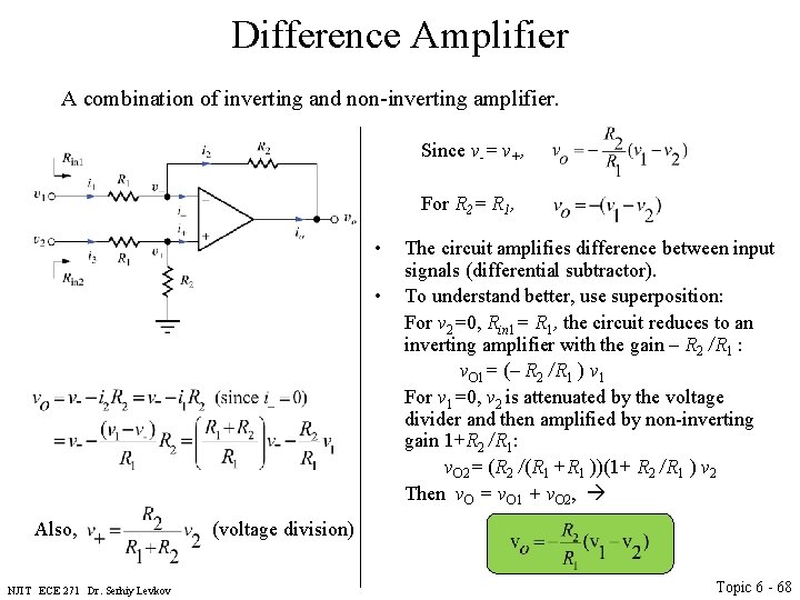
Difference Amplifier A combination of inverting and non-inverting amplifier. Since v-= v+, For R 2= R 1, • • The circuit amplifies difference between input signals (differential subtractor). To understand better, use superposition: For v 2=0, Rin 1= R 1, the circuit reduces to an inverting amplifier with the gain – R 2 /R 1 : v. O 1= (– R 2 /R 1 ) v 1 For v 1=0, v 2 is attenuated by the voltage divider and then amplified by non-inverting gain 1+R 2 /R 1: v. O 2= (R 2 /(R 1 +R 1 ))(1+ R 2 /R 1 ) v 2 Then v. O = v. O 1 + v. O 2, Also, (voltage division) NJIT ECE 271 Dr. Serhiy Levkov Topic 6 - 68
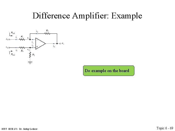
Difference Amplifier: Example Do example on the board NJIT ECE 271 Dr. Serhiy Levkov Topic 6 - 69
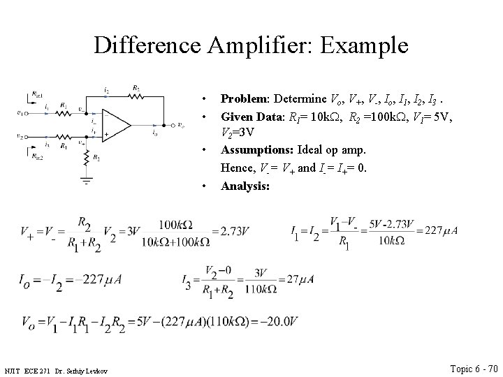
Difference Amplifier: Example • • NJIT ECE 271 Dr. Serhiy Levkov Problem: Determine Vo, V+, V-, Io, I 1, I 2, I 3. Given Data: R 1= 10 k. W, R 2 =100 k. W, V 1= 5 V, V 2=3 V Assumptions: Ideal op amp. Hence, V-= V+ and I-= I+= 0. Analysis: Topic 6 - 70
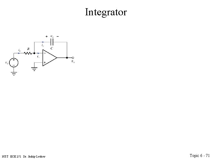
Integrator NJIT ECE 271 Dr. Serhiy Levkov Topic 6 - 71
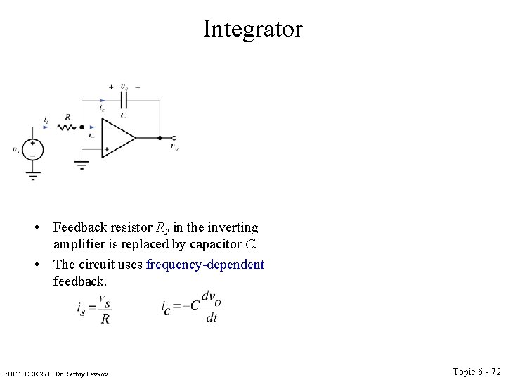
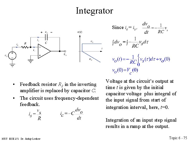
Integrator • Feedback resistor R 2 in the inverting amplifier is replaced by capacitor C. • The circuit uses frequency-dependent feedback. NJIT ECE 271 Dr. Serhiy Levkov Topic 6 - 72
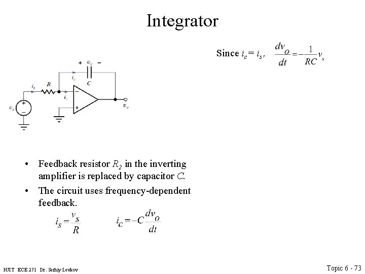
Integrator Since ic= is , • Feedback resistor R 2 in the inverting amplifier is replaced by capacitor C. • The circuit uses frequency-dependent feedback. NJIT ECE 271 Dr. Serhiy Levkov Topic 6 - 73
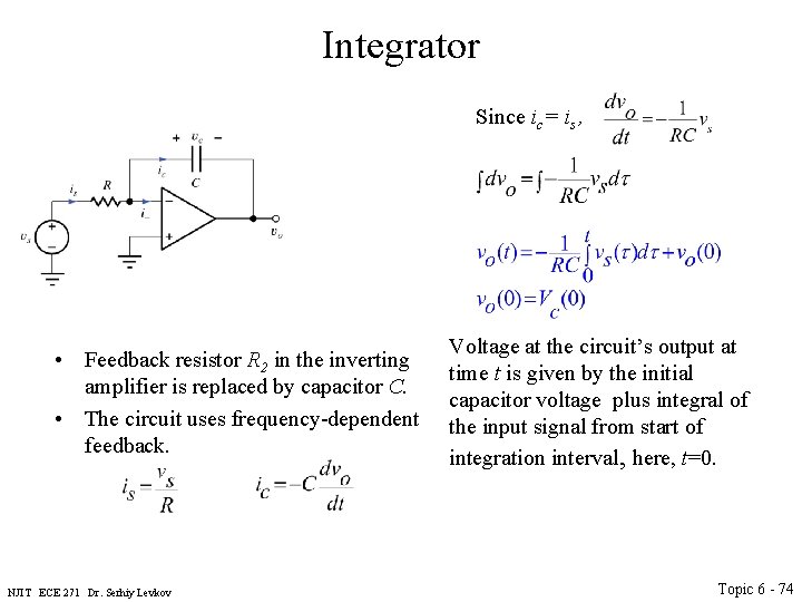
Integrator Since ic= is , • Feedback resistor R 2 in the inverting amplifier is replaced by capacitor C. • The circuit uses frequency-dependent feedback. NJIT ECE 271 Dr. Serhiy Levkov Voltage at the circuit’s output at time t is given by the initial capacitor voltage plus integral of the input signal from start of integration interval, here, t=0. Topic 6 - 74
Integrator Since ic= is , • Feedback resistor R 2 in the inverting amplifier is replaced by capacitor C. • The circuit uses frequency-dependent feedback. Voltage at the circuit’s output at time t is given by the initial capacitor voltage plus integral of the input signal from start of integration interval, here, t=0. Integration of an input step signal results in a ramp at the output. NJIT ECE 271 Dr. Serhiy Levkov Topic 6 - 75
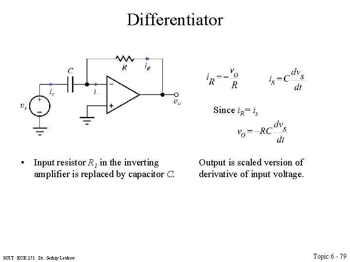
Differentiator NJIT ECE 271 Dr. Serhiy Levkov Topic 6 - 76
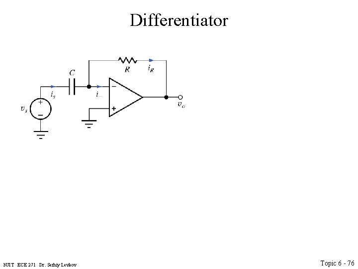
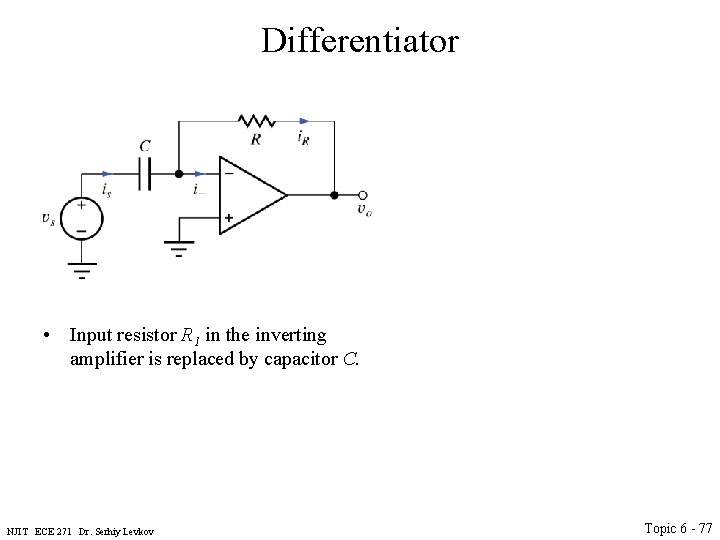
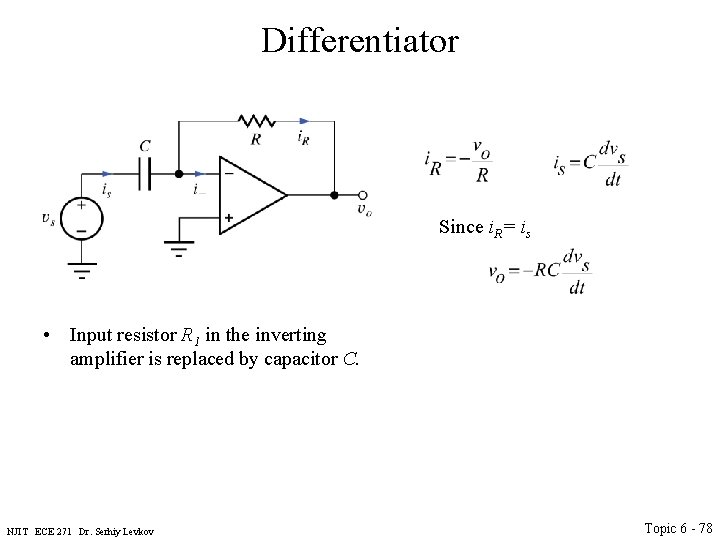
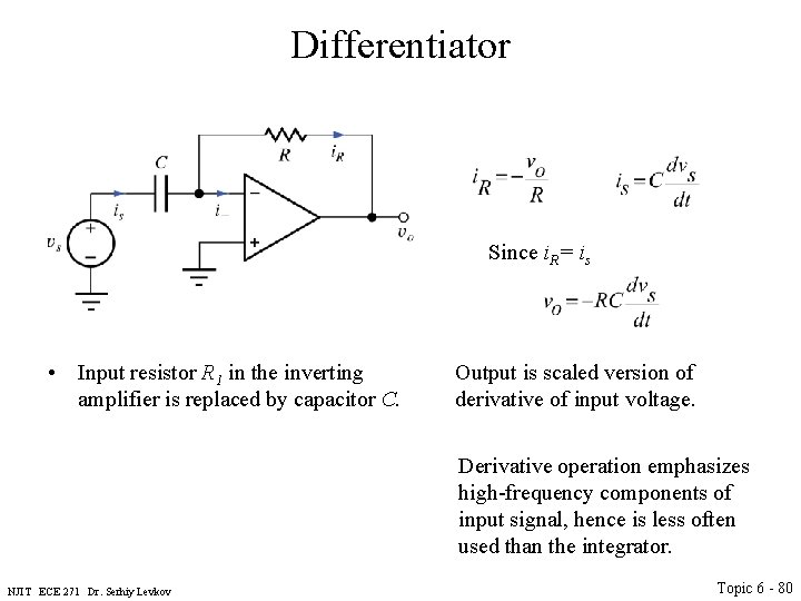
Differentiator • Input resistor R 1 in the inverting amplifier is replaced by capacitor C. NJIT ECE 271 Dr. Serhiy Levkov Topic 6 - 77
Differentiator Since i. R= is • Input resistor R 1 in the inverting amplifier is replaced by capacitor C. NJIT ECE 271 Dr. Serhiy Levkov Topic 6 - 78
Differentiator Since i. R= is • Input resistor R 1 in the inverting amplifier is replaced by capacitor C. NJIT ECE 271 Dr. Serhiy Levkov Output is scaled version of derivative of input voltage. Topic 6 - 79
Differentiator Since i. R= is • Input resistor R 1 in the inverting amplifier is replaced by capacitor C. Output is scaled version of derivative of input voltage. Derivative operation emphasizes high-frequency components of input signal, hence is less often used than the integrator. NJIT ECE 271 Dr. Serhiy Levkov Topic 6 - 80
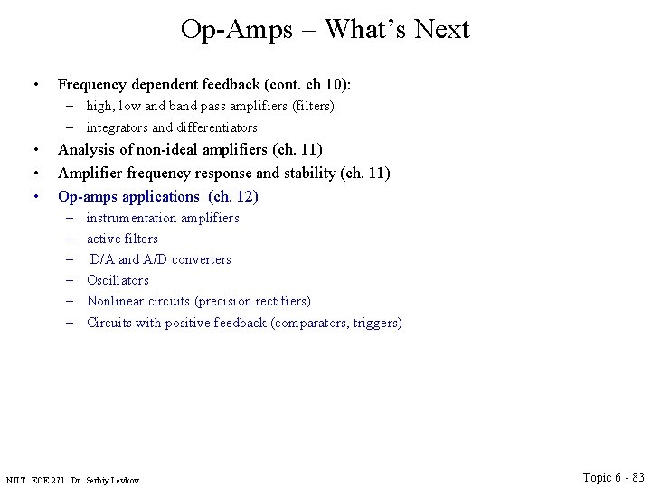
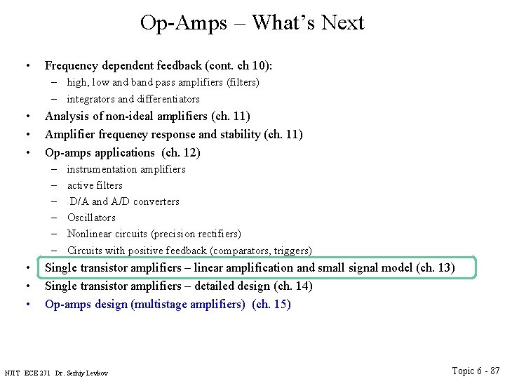
Op-Amps – What’s Next • Frequency dependent feedback (cont. ch 10): – high, low and band pass amplifiers (filters) – integrators and differentiators NJIT ECE 271 Dr. Serhiy Levkov Topic 6 - 81
Op-Amps – What’s Next • Frequency dependent feedback (cont. ch 10): – high, low and band pass amplifiers (filters) – integrators and differentiators • • Analysis of non-ideal amplifiers (ch. 11) Amplifier frequency response and stability (ch. 11) NJIT ECE 271 Dr. Serhiy Levkov Topic 6 - 82
Op-Amps – What’s Next • Frequency dependent feedback (cont. ch 10): – high, low and band pass amplifiers (filters) – integrators and differentiators • • • Analysis of non-ideal amplifiers (ch. 11) Amplifier frequency response and stability (ch. 11) Op-amps applications (ch. 12) – – – instrumentation amplifiers active filters D/A and A/D converters Oscillators Nonlinear circuits (precision rectifiers) Circuits with positive feedback (comparators, triggers) NJIT ECE 271 Dr. Serhiy Levkov Topic 6 - 83
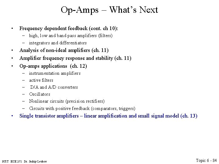
Op-Amps – What’s Next • Frequency dependent feedback (cont. ch 10): – high, low and band pass amplifiers (filters) – integrators and differentiators • • • Analysis of non-ideal amplifiers (ch. 11) Amplifier frequency response and stability (ch. 11) Op-amps applications (ch. 12) – – – • instrumentation amplifiers active filters D/A and A/D converters Oscillators Nonlinear circuits (precision rectifiers) Circuits with positive feedback (comparators, triggers) Single transistor amplifiers – linear amplification and small signal model (ch. 13) NJIT ECE 271 Dr. Serhiy Levkov Topic 6 - 84
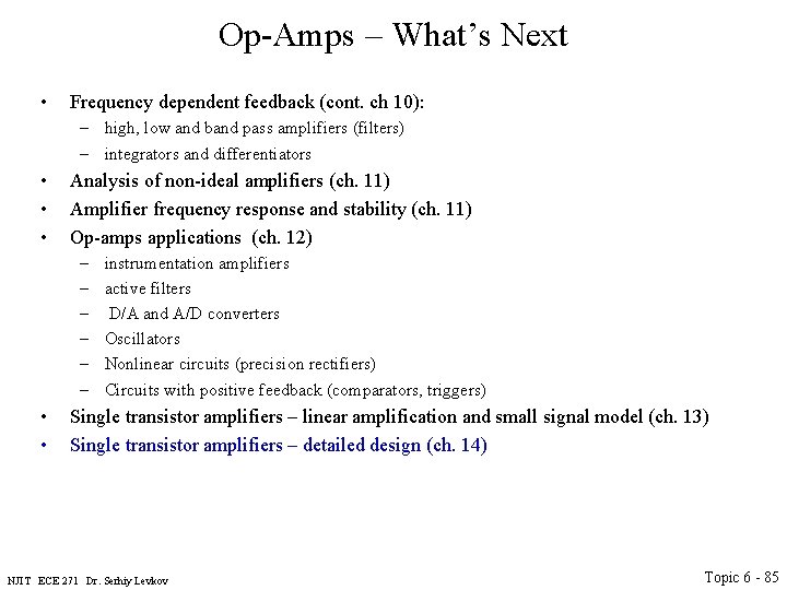
Op-Amps – What’s Next • Frequency dependent feedback (cont. ch 10): – high, low and band pass amplifiers (filters) – integrators and differentiators • • • Analysis of non-ideal amplifiers (ch. 11) Amplifier frequency response and stability (ch. 11) Op-amps applications (ch. 12) – – – • • instrumentation amplifiers active filters D/A and A/D converters Oscillators Nonlinear circuits (precision rectifiers) Circuits with positive feedback (comparators, triggers) Single transistor amplifiers – linear amplification and small signal model (ch. 13) Single transistor amplifiers – detailed design (ch. 14) NJIT ECE 271 Dr. Serhiy Levkov Topic 6 - 85
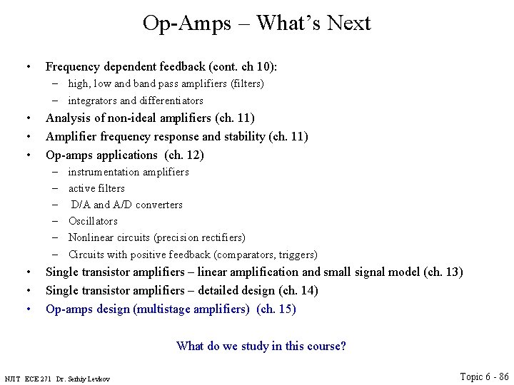
Op-Amps – What’s Next • Frequency dependent feedback (cont. ch 10): – high, low and band pass amplifiers (filters) – integrators and differentiators • • • Analysis of non-ideal amplifiers (ch. 11) Amplifier frequency response and stability (ch. 11) Op-amps applications (ch. 12) – – – • • • instrumentation amplifiers active filters D/A and A/D converters Oscillators Nonlinear circuits (precision rectifiers) Circuits with positive feedback (comparators, triggers) Single transistor amplifiers – linear amplification and small signal model (ch. 13) Single transistor amplifiers – detailed design (ch. 14) Op-amps design (multistage amplifiers) (ch. 15) What do we study in this course? NJIT ECE 271 Dr. Serhiy Levkov Topic 6 - 86
Op-Amps – What’s Next • Frequency dependent feedback (cont. ch 10): – high, low and band pass amplifiers (filters) – integrators and differentiators • • • Analysis of non-ideal amplifiers (ch. 11) Amplifier frequency response and stability (ch. 11) Op-amps applications (ch. 12) – – – • • • instrumentation amplifiers active filters D/A and A/D converters Oscillators Nonlinear circuits (precision rectifiers) Circuits with positive feedback (comparators, triggers) Single transistor amplifiers – linear amplification and small signal model (ch. 13) Single transistor amplifiers – detailed design (ch. 14) Op-amps design (multistage amplifiers) (ch. 15) NJIT ECE 271 Dr. Serhiy Levkov Topic 6 - 87
Transistors as Amplifiers NJIT ECE 271 Dr. Serhiy Levkov Topic 6 - 88
Transistors as Amplifiers In this section we will study • The general techniques for employing individual transistors as amplifiers NJIT ECE 271 Dr. Serhiy Levkov Topic 6 - 89
Transistors as Amplifiers In this section we will study • The general techniques for employing individual transistors as amplifiers • Operation of common source MOSFET amplifier NJIT ECE 271 Dr. Serhiy Levkov Topic 6 - 90
Transistors as Amplifiers In this section we will study • The general techniques for employing individual transistors as amplifiers • Operation of common source MOSFET amplifier • Operation of common emitter BJT amplifier NJIT ECE 271 Dr. Serhiy Levkov Topic 6 - 91
Transistors as Amplifiers In this section we will study • The general techniques for employing individual transistors as amplifiers • Operation of common source MOSFET amplifier • Operation of common emitter BJT amplifier What do we know: • MOSFET (FET) can be used as amplifier if operated in saturation region (SR) NJIT ECE 271 Dr. Serhiy Levkov Topic 6 - 92
Transistors as Amplifiers In this section we will study • The general techniques for employing individual transistors as amplifiers • Operation of common source MOSFET amplifier • Operation of common emitter BJT amplifier What do we know: • MOSFET (FET) can be used as amplifier if operated in saturation region (SR) • BJT can be used as an amplifier when biased in the forward-active region (FAR) NJIT ECE 271 Dr. Serhiy Levkov Topic 6 - 93
Transistors as Amplifiers In this section we will study • The general techniques for employing individual transistors as amplifiers • Operation of common source MOSFET amplifier • Operation of common emitter BJT amplifier What do we know: • MOSFET (FET) can be used as amplifier if operated in saturation region (SR) • BJT can be used as an amplifier when biased in the forward-active region (FAR) • We will refer to the FAR and SR as to the “active region” NJIT ECE 271 Dr. Serhiy Levkov Topic 6 - 94
Transistors as Amplifiers In this section we will study • The general techniques for employing individual transistors as amplifiers • Operation of common source MOSFET amplifier • Operation of common emitter BJT amplifier What do we know: • MOSFET (FET) can be used as amplifier if operated in saturation region (SR) • BJT can be used as an amplifier when biased in the forward-active region (FAR) • We will refer to the FAR and SR as to the “active region” • In these regions, transistors can provide high voltage, current and power gains NJIT ECE 271 Dr. Serhiy Levkov Topic 6 - 95
Transistors as Amplifiers In this section we will study • The general techniques for employing individual transistors as amplifiers • Operation of common source MOSFET amplifier • Operation of common emitter BJT amplifier What do we know: • MOSFET (FET) can be used as amplifier if operated in saturation region (SR) • BJT can be used as an amplifier when biased in the forward-active region (FAR) • We will refer to the FAR and SR as to the “active region” • In these regions, transistors can provide high voltage, current and power gains • Bias is provided to stabilize the operating point in a desired operation region NJIT ECE 271 Dr. Serhiy Levkov Topic 6 - 96
Transistors as Amplifiers In this section we will study • The general techniques for employing individual transistors as amplifiers • Operation of common source MOSFET amplifier • Operation of common emitter BJT amplifier What do we know: • MOSFET (FET) can be used as amplifier if operated in saturation region (SR) • BJT can be used as an amplifier when biased in the forward-active region (FAR) • We will refer to the FAR and SR as to the “active region” • In these regions, transistors can provide high voltage, current and power gains • Bias is provided to stabilize the operating point in a desired operation region • The Q-point also determines – – Small-signal parameters of transistor Voltage gain, input resistance, output resistance Maximum input and output signal amplitudes Power consumption NJIT ECE 271 Dr. Serhiy Levkov Topic 6 - 97
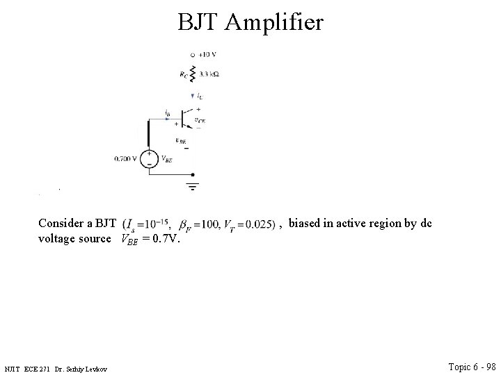
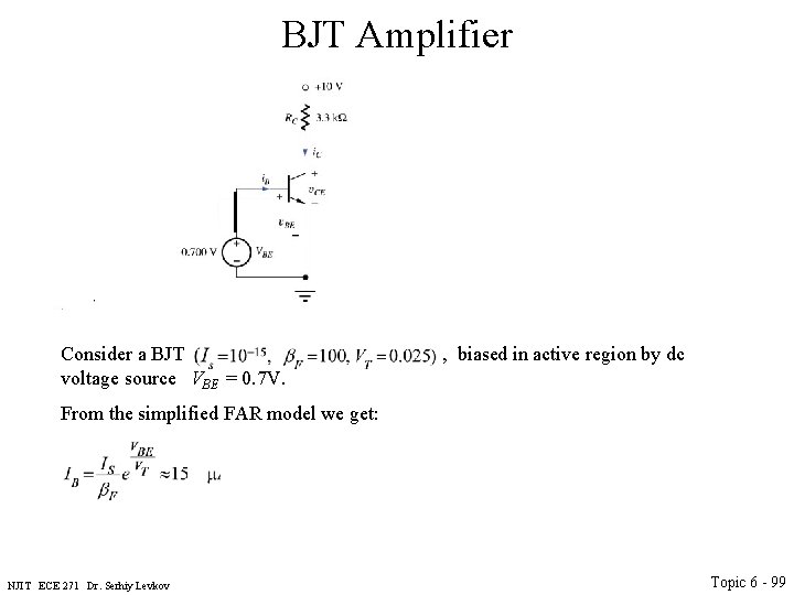
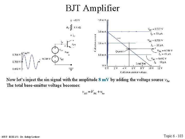
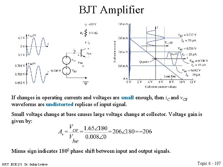
BJT Amplifier Consider a BJT , biased in active region by dc voltage source VBE = 0. 7 V. NJIT ECE 271 Dr. Serhiy Levkov Topic 6 - 98
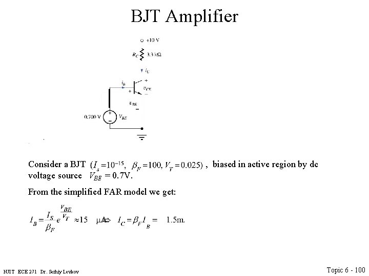
BJT Amplifier Consider a BJT , biased in active region by dc voltage source VBE = 0. 7 V. From the simplified FAR model we get: NJIT ECE 271 Dr. Serhiy Levkov Topic 6 - 99
BJT Amplifier Consider a BJT , biased in active region by dc voltage source VBE = 0. 7 V. From the simplified FAR model we get: NJIT ECE 271 Dr. Serhiy Levkov Topic 6 - 100
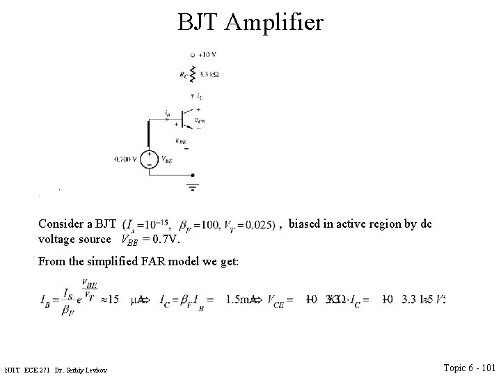
BJT Amplifier Consider a BJT , biased in active region by dc voltage source VBE = 0. 7 V. From the simplified FAR model we get: NJIT ECE 271 Dr. Serhiy Levkov Topic 6 - 101
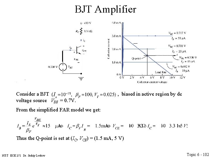
BJT Amplifier Consider a BJT , biased in active region by dc voltage source VBE = 0. 7 V. From the simplified FAR model we get: Thus the Q-point is set at (IC, VCE) = (1. 5 m. A, 5 V) NJIT ECE 271 Dr. Serhiy Levkov Topic 6 - 102
BJT Amplifier Now let’s inject the sin signal with the amplitude 8 m. V by adding the voltage source vbe The total base-emitter voltage becomes: NJIT ECE 271 Dr. Serhiy Levkov Topic 6 - 103
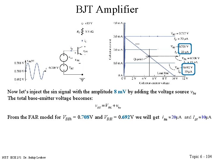
BJT Amplifier Now let’s inject the sin signal with the amplitude 8 m. V by adding the voltage source vbe The total base-emitter voltage becomes: From the FAR model for VBEh = 0. 708 V and VBEl = 0. 692 V we will get NJIT ECE 271 Dr. Serhiy Levkov Topic 6 - 104
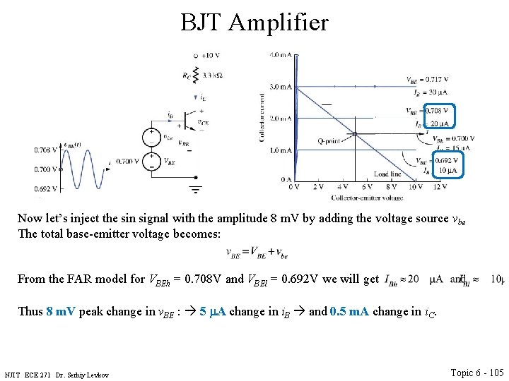
BJT Amplifier Now let’s inject the sin signal with the amplitude 8 m. V by adding the voltage source vbe The total base-emitter voltage becomes: From the FAR model for VBEh = 0. 708 V and VBEl = 0. 692 V we will get Thus 8 m. V peak change in v. BE : 5 m. A change in i. B and 0. 5 m. A change in i. C. NJIT ECE 271 Dr. Serhiy Levkov Topic 6 - 105
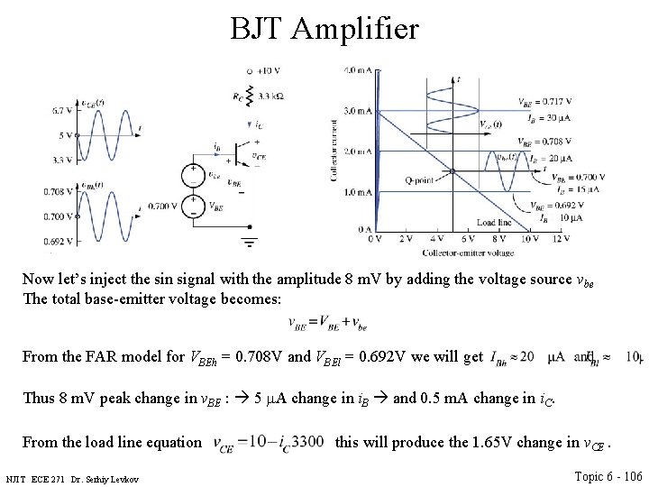
BJT Amplifier Now let’s inject the sin signal with the amplitude 8 m. V by adding the voltage source vbe The total base-emitter voltage becomes: From the FAR model for VBEh = 0. 708 V and VBEl = 0. 692 V we will get Thus 8 m. V peak change in v. BE : 5 m. A change in i. B and 0. 5 m. A change in i. C. From the load line equation this will produce the 1. 65 V change in v. CE. NJIT ECE 271 Dr. Serhiy Levkov Topic 6 - 106
BJT Amplifier If changes in operating currents and voltages are small enough, then i. C and v. CE waveforms are undistorted replicas of input signal. Small voltage change at base causes large voltage change at collector. Voltage gain is given by: Minus sign indicates 1800 phase shift between input and output signals. NJIT ECE 271 Dr. Serhiy Levkov Topic 6 - 107
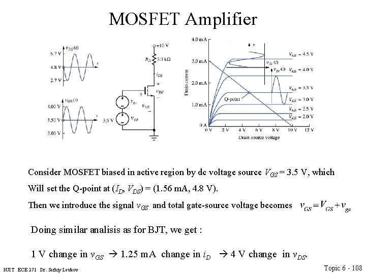
MOSFET Amplifier Consider MOSFET biased in active region by dc voltage source VGS = 3. 5 V, which Will set the Q-point at (ID, VDS) = (1. 56 m. A, 4. 8 V). Then we introduce the signal v. GS and total gate-source voltage becomes Doing similar analisis as for BJT, we get : 1 V change in v. GS 1. 25 m. A change in i. D 4 V change in v. DS. NJIT ECE 271 Dr. Serhiy Levkov Topic 6 - 108
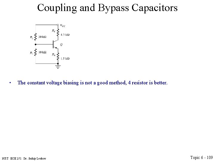
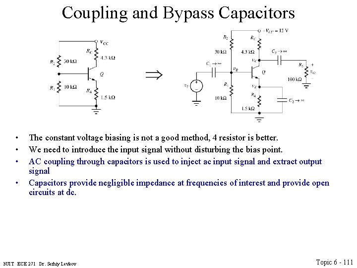
Coupling and Bypass Capacitors • The constant voltage biasing is not a good method, 4 resistor is better. NJIT ECE 271 Dr. Serhiy Levkov Topic 6 - 109
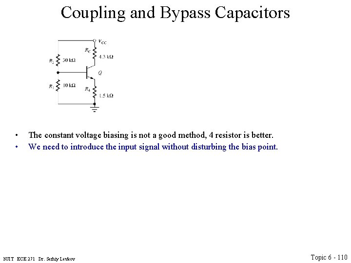
Coupling and Bypass Capacitors • • The constant voltage biasing is not a good method, 4 resistor is better. We need to introduce the input signal without disturbing the bias point. NJIT ECE 271 Dr. Serhiy Levkov Topic 6 - 110
Coupling and Bypass Capacitors • • The constant voltage biasing is not a good method, 4 resistor is better. We need to introduce the input signal without disturbing the bias point. AC coupling through capacitors is used to inject ac input signal and extract output signal Capacitors provide negligible impedance at frequencies of interest and provide open circuits at dc. NJIT ECE 271 Dr. Serhiy Levkov Topic 6 - 111
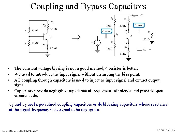
Coupling and Bypass Capacitors • • The constant voltage biasing is not a good method, 4 resistor is better. We need to introduce the input signal without disturbing the bias point. AC coupling through capacitors is used to inject ac input signal and extract output signal Capacitors provide negligible impedance at frequencies of interest and provide open circuits at dc. C 1 and C 3 are large-valued coupling capacitors or dc blocking capacitors whose reactance at the signal frequency is designed to be negligible. NJIT ECE 271 Dr. Serhiy Levkov Topic 6 - 112
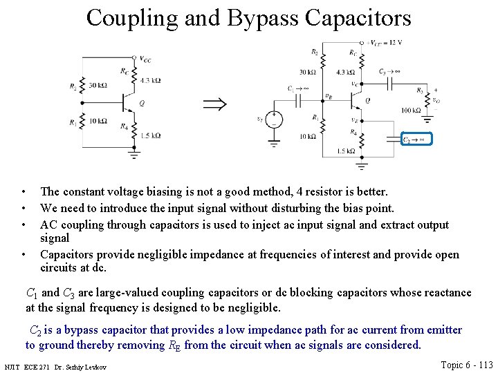
Coupling and Bypass Capacitors • • The constant voltage biasing is not a good method, 4 resistor is better. We need to introduce the input signal without disturbing the bias point. AC coupling through capacitors is used to inject ac input signal and extract output signal Capacitors provide negligible impedance at frequencies of interest and provide open circuits at dc. C 1 and C 3 are large-valued coupling capacitors or dc blocking capacitors whose reactance at the signal frequency is designed to be negligible. C 2 is a bypass capacitor that provides a low impedance path for ac current from emitter to ground thereby removing RE from the circuit when ac signals are considered. NJIT ECE 271 Dr. Serhiy Levkov Topic 6 - 113
DC and AC Analysis • DC analysis: – Make dc equivalent circuit by replacing all capacitors by open circuits and inductors by short circuits. – Find Q-point from dc equivalent circuit by using appropriate largesignal transistor model. NJIT ECE 271 Dr. Serhiy Levkov Topic 6 - 114
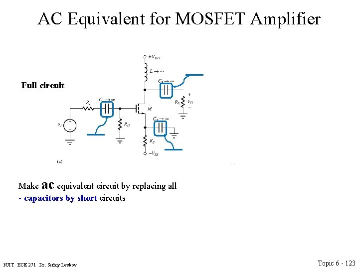
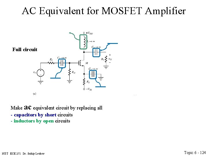
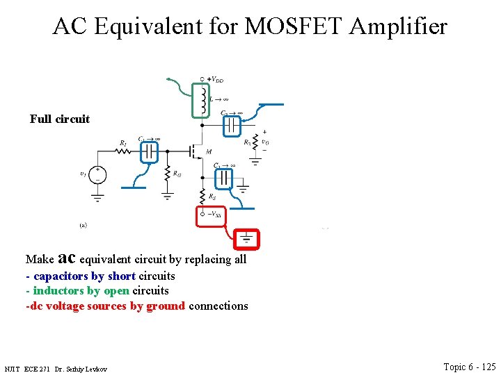
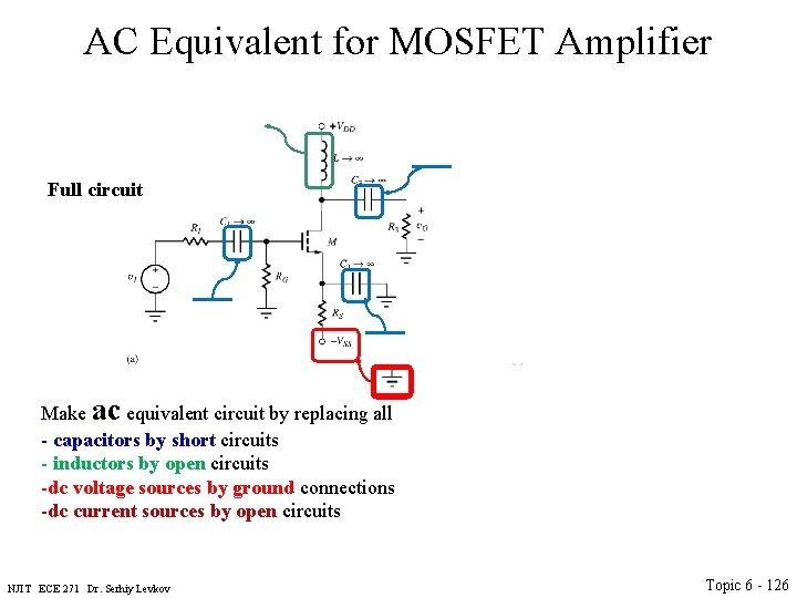
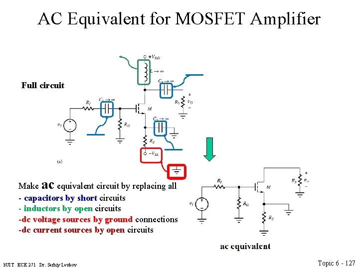
DC and AC Analysis • DC analysis: – Make dc equivalent circuit by replacing all capacitors by open circuits and inductors by short circuits. – Find Q-point from dc equivalent circuit by using appropriate largesignal transistor model. • AC analysis: – Make ac equivalent circuit by replacing all capacitors by short circuits, inductors by open circuits, dc voltage sources by ground connections and dc current sources by open circuits. NJIT ECE 271 Dr. Serhiy Levkov Topic 6 - 115
DC and AC Analysis • DC analysis: – Make dc equivalent circuit by replacing all capacitors by open circuits and inductors by short circuits. – Find Q-point from dc equivalent circuit by using appropriate largesignal transistor model. • AC analysis: – Make ac equivalent circuit by replacing all capacitors by short circuits, inductors by open circuits, dc voltage sources by ground connections and dc current sources by open circuits. – Replace transistor by small-signal model NJIT ECE 271 Dr. Serhiy Levkov Topic 6 - 116
DC and AC Analysis • DC analysis: – Make dc equivalent circuit by replacing all capacitors by open circuits and inductors by short circuits. – Find Q-point from dc equivalent circuit by using appropriate largesignal transistor model. • AC analysis: – Make ac equivalent circuit by replacing all capacitors by short circuits, inductors by open circuits, dc voltage sources by ground connections and dc current sources by open circuits. – Replace transistor by small-signal model – Use small-signal ac equivalent to analyze ac characteristics of amplifier. NJIT ECE 271 Dr. Serhiy Levkov Topic 6 - 117
DC and AC Analysis • DC analysis: – Make dc equivalent circuit by replacing all capacitors by open circuits and inductors by short circuits. – Find Q-point from dc equivalent circuit by using appropriate largesignal transistor model. • AC analysis: – Make ac equivalent circuit by replacing all capacitors by short circuits, inductors by open circuits, dc voltage sources by ground connections and dc current sources by open circuits. – Replace transistor by small-signal model – Use small-signal ac equivalent to analyze ac characteristics of amplifier. – Combine end results of dc and ac analysis to yield total voltages and currents in the network. NJIT ECE 271 Dr. Serhiy Levkov Topic 6 - 118
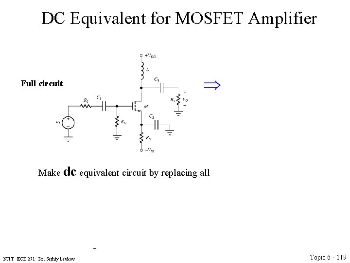
DC Equivalent for MOSFET Amplifier Full circuit dc equivalent Make dc equivalent circuit by replacing all ac equivalent NJIT ECE 271 Dr. Serhiy Levkov Simplified ac equivalent Topic 6 - 119
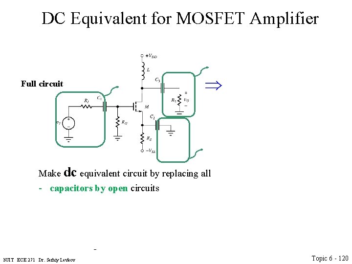
DC Equivalent for MOSFET Amplifier Full circuit dc equivalent Make dc equivalent circuit by replacing all - capacitors by open circuits ac equivalent NJIT ECE 271 Dr. Serhiy Levkov Simplified ac equivalent Topic 6 - 120
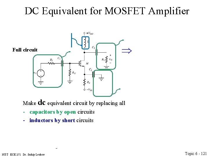
DC Equivalent for MOSFET Amplifier Full circuit dc equivalent Make dc equivalent circuit by replacing all - capacitors by open circuits - inductors by short circuits ac equivalent NJIT ECE 271 Dr. Serhiy Levkov Simplified ac equivalent Topic 6 - 121
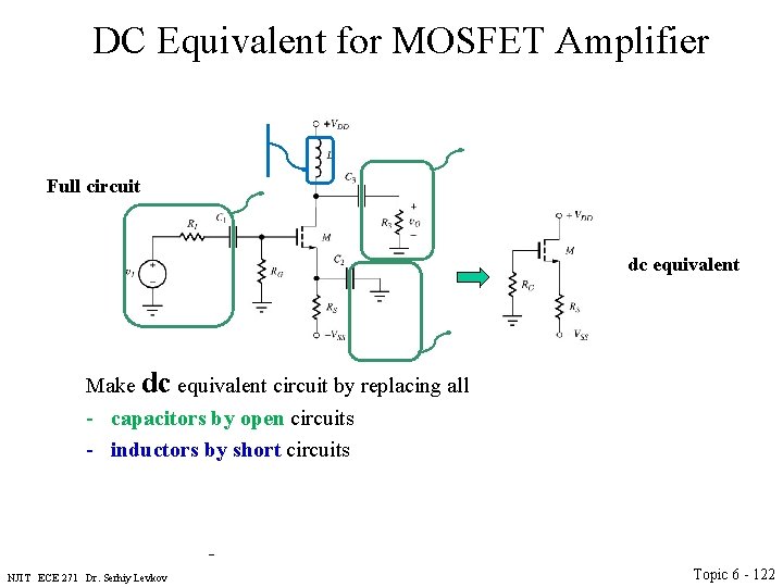
DC Equivalent for MOSFET Amplifier Full circuit dc equivalent Make dc equivalent circuit by replacing all - capacitors by open circuits - inductors by short circuits ac equivalent NJIT ECE 271 Dr. Serhiy Levkov Simplified ac equivalent Topic 6 - 122
AC Equivalent for MOSFET Amplifier Full circuit dc equivalent Make ac equivalent circuit by replacing all - capacitors by short circuits ac equivalent NJIT ECE 271 Dr. Serhiy Levkov Simplified ac equivalent Topic 6 - 123
AC Equivalent for MOSFET Amplifier Full circuit dc equivalent Make ac equivalent circuit by replacing all - capacitors by short circuits - inductors by open circuits ac equivalent NJIT ECE 271 Dr. Serhiy Levkov Simplified ac equivalent Topic 6 - 124
AC Equivalent for MOSFET Amplifier Full circuit dc equivalent Make ac equivalent circuit by replacing all - capacitors by short circuits - inductors by open circuits -dc voltage sources by ground connections ac equivalent NJIT ECE 271 Dr. Serhiy Levkov Simplified ac equivalent Topic 6 - 125
AC Equivalent for MOSFET Amplifier Full circuit dc equivalent Make ac equivalent circuit by replacing all - capacitors by short circuits - inductors by open circuits -dc voltage sources by ground connections -dc current sources by open circuits ac equivalent NJIT ECE 271 Dr. Serhiy Levkov Simplified ac equivalent Topic 6 - 126
AC Equivalent for MOSFET Amplifier Full circuit dc equivalent Make ac equivalent circuit by replacing all - capacitors by short circuits - inductors by open circuits -dc voltage sources by ground connections -dc current sources by open circuits ac equivalent NJIT ECE 271 Dr. Serhiy Levkov Simplified ac equivalent Topic 6 - 127
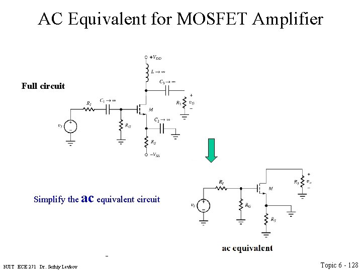
AC Equivalent for MOSFET Amplifier Full circuit dc equivalent Simplify the ac equivalent circuit ac equivalent NJIT ECE 271 Dr. Serhiy Levkov Simplified ac equivalent Topic 6 - 128
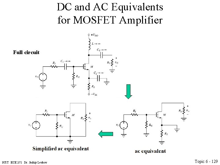
DC and AC Equivalents for MOSFET Amplifier Full circuit dc equivalent ac equivalent NJIT ECE 271 Dr. Serhiy Levkov Simplified ac equivalent Topic 6 - 129
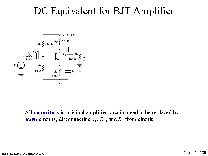
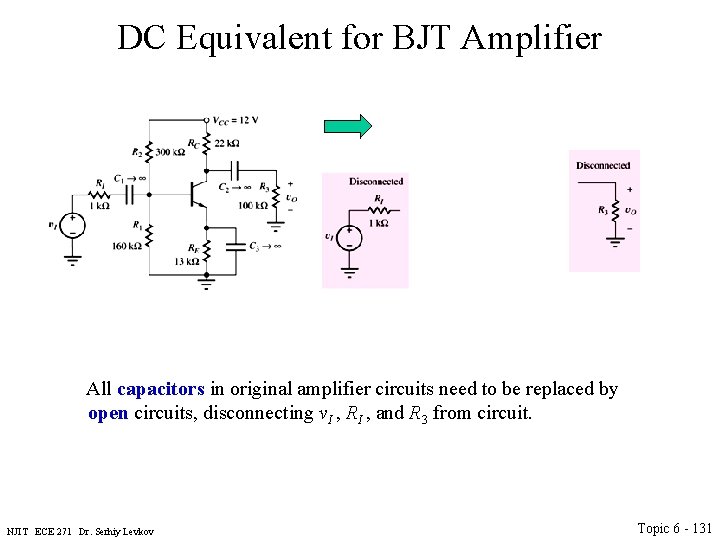
DC Equivalent for BJT Amplifier All capacitors in original amplifier circuits need to be replaced by open circuits, disconnecting v. I , RI , and R 3 from circuit. NJIT ECE 271 Dr. Serhiy Levkov Topic 6 - 130
DC Equivalent for BJT Amplifier All capacitors in original amplifier circuits need to be replaced by open circuits, disconnecting v. I , RI , and R 3 from circuit. NJIT ECE 271 Dr. Serhiy Levkov Topic 6 - 131
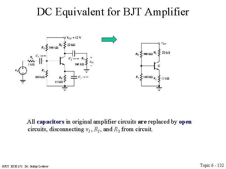
DC Equivalent for BJT Amplifier All capacitors in original amplifier circuits are replaced by open circuits, disconnecting v. I , RI , and R 3 from circuit. NJIT ECE 271 Dr. Serhiy Levkov Topic 6 - 132
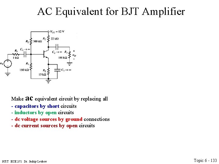
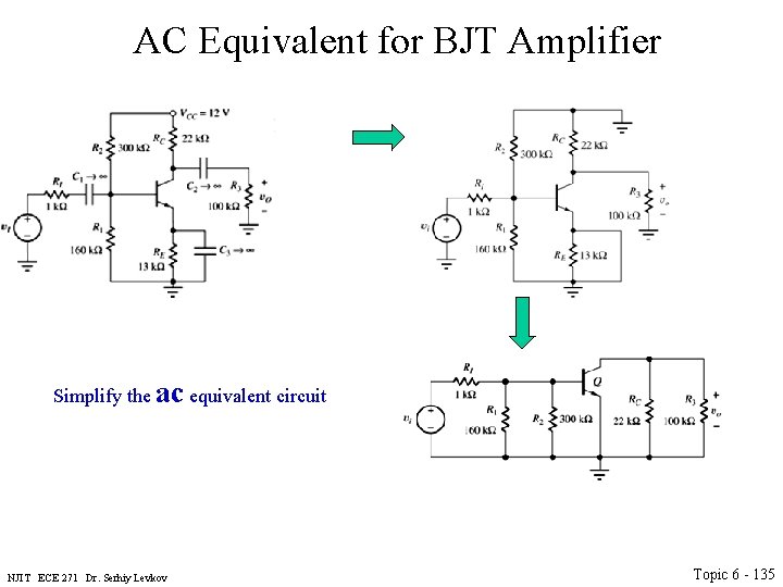
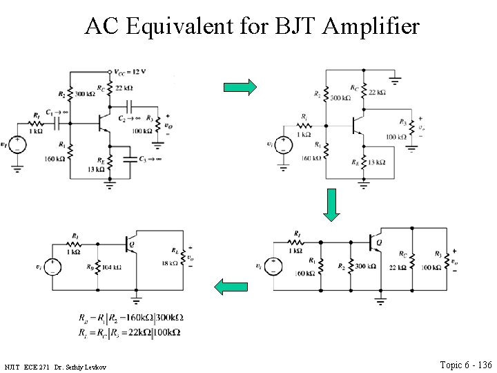
AC Equivalent for BJT Amplifier Make ac equivalent circuit by replacing all - capacitors by short circuits - inductors by open circuits - dc voltage sources by ground connections - dc current sources by open circuits NJIT ECE 271 Dr. Serhiy Levkov Topic 6 - 133
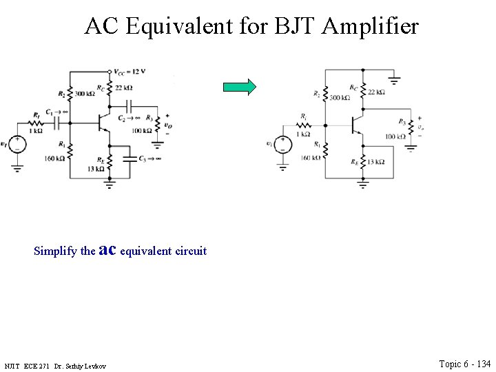
AC Equivalent for BJT Amplifier Simplify the ac equivalent circuit NJIT ECE 271 Dr. Serhiy Levkov Topic 6 - 134
AC Equivalent for BJT Amplifier Simplify the ac equivalent circuit NJIT ECE 271 Dr. Serhiy Levkov Topic 6 - 135
AC Equivalent for BJT Amplifier NJIT ECE 271 Dr. Serhiy Levkov Topic 6 - 136
Small-Signal Modeling • For AC analysis (or general time varying analysis) we would need to use phasor , time domain, Laplace Transform (or similar) methods. • Those are working better with linear systems. • Need to make the linear model – small signal model. • Assume that the time varying components are small signals and construct the two port model, which is linear. • The concept of small signal is device dependent. • We start from developing small signal model for a diode and then switch to transistor NJIT ECE 271 Dr. Serhiy Levkov Topic 6 - 137
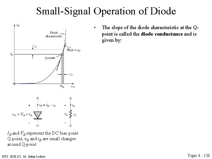
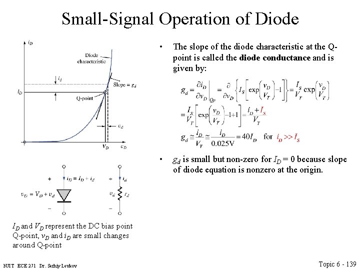
Small-Signal Operation of Diode • The slope of the diode characteristic at the Qpoint is called the diode conductance and is given by: ID and VD represent the DC bias point Q-point, v. D and i. D are small changes around Q-point NJIT ECE 271 Dr. Serhiy Levkov Topic 6 - 138
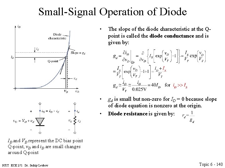
Small-Signal Operation of Diode • The slope of the diode characteristic at the Qpoint is called the diode conductance and is given by: • gd is small but non-zero for ID = 0 because slope of diode equation is nonzero at the origin. ID and VD represent the DC bias point Q-point, v. D and i. D are small changes around Q-point NJIT ECE 271 Dr. Serhiy Levkov Topic 6 - 139
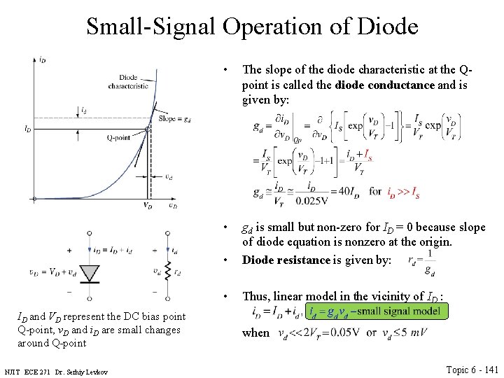
Small-Signal Operation of Diode • The slope of the diode characteristic at the Qpoint is called the diode conductance and is given by: • gd is small but non-zero for ID = 0 because slope of diode equation is nonzero at the origin. Diode resistance is given by: • ID and VD represent the DC bias point Q-point, v. D and i. D are small changes around Q-point NJIT ECE 271 Dr. Serhiy Levkov Topic 6 - 140
Small-Signal Operation of Diode ID and VD represent the DC bias point Q-point, v. D and i. D are small changes around Q-point NJIT ECE 271 Dr. Serhiy Levkov • The slope of the diode characteristic at the Qpoint is called the diode conductance and is given by: • • gd is small but non-zero for ID = 0 because slope of diode equation is nonzero at the origin. Diode resistance is given by: • Thus, linear model in the vicinity of ID : when Topic 6 - 141
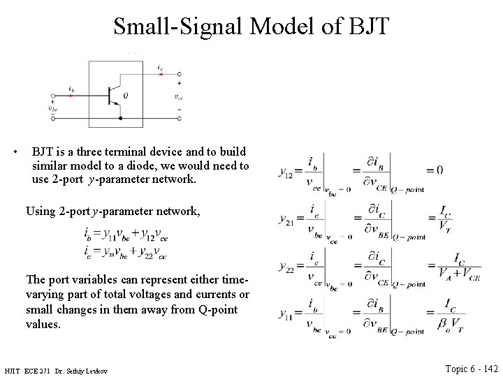
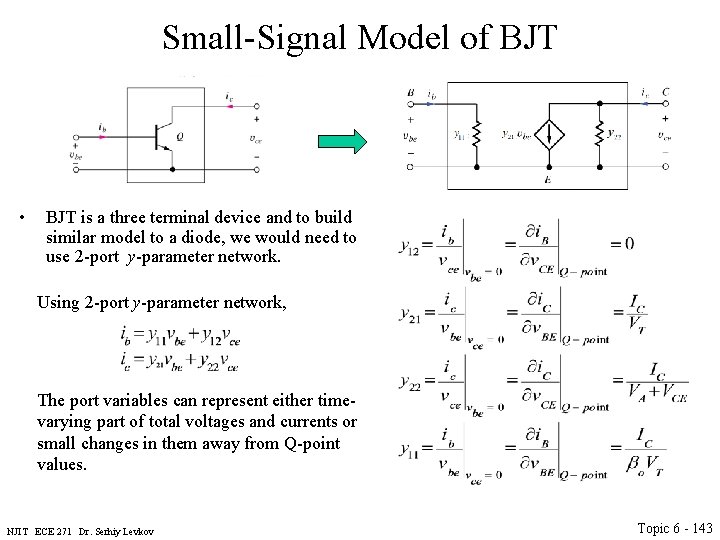
Small-Signal Model of BJT • BJT is a three terminal device and to build similar model to a diode, we would need to use 2 -port y-parameter network. Using 2 -port y-parameter network, The port variables can represent either timevarying part of total voltages and currents or small changes in them away from Q-point values. NJIT ECE 271 Dr. Serhiy Levkov Topic 6 - 142
Small-Signal Model of BJT • BJT is a three terminal device and to build similar model to a diode, we would need to use 2 -port y-parameter network. Using 2 -port y-parameter network, The port variables can represent either timevarying part of total voltages and currents or small changes in them away from Q-point values. NJIT ECE 271 Dr. Serhiy Levkov Topic 6 - 143
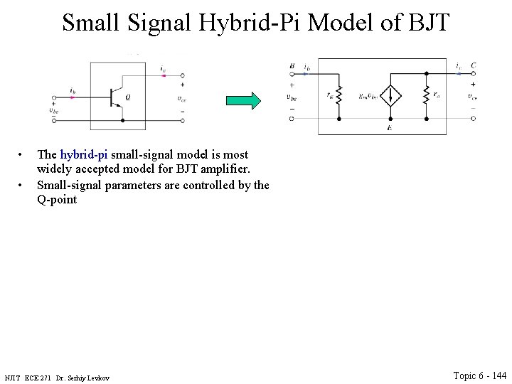
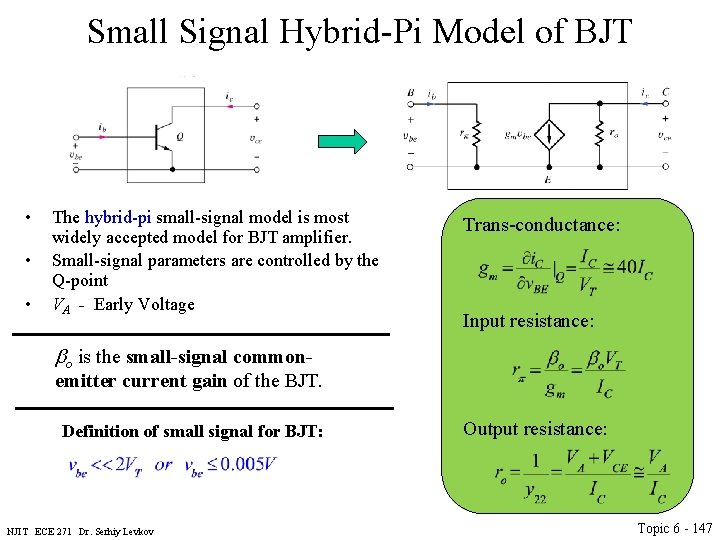
Small Signal Hybrid-Pi Model of BJT • • The hybrid-pi small-signal model is most widely accepted model for BJT amplifier. Small-signal parameters are controlled by the Q-point NJIT ECE 271 Dr. Serhiy Levkov Topic 6 - 144
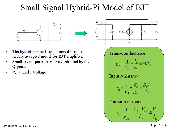
Small Signal Hybrid-Pi Model of BJT • • • The hybrid-pi small-signal model is most widely accepted model for BJT amplifier. Small-signal parameters are controlled by the Q-point VA - Early Voltage Trans-conductance: Input resistance: Output resistance: NJIT ECE 271 Dr. Serhiy Levkov Topic 6 - 145
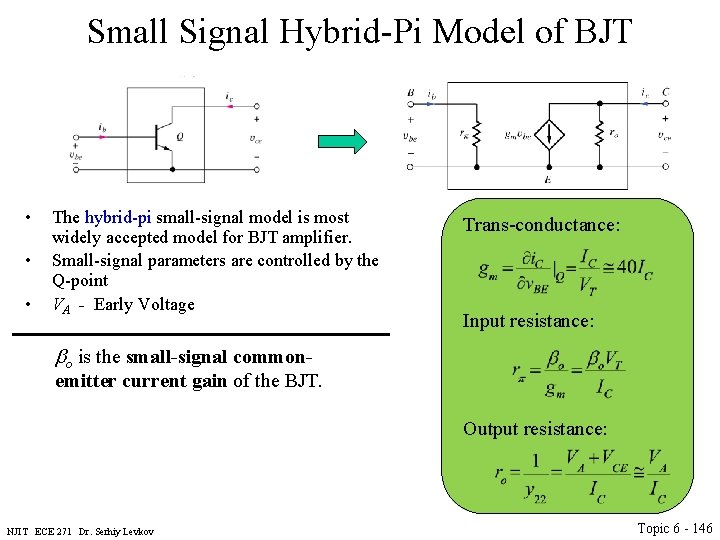
Small Signal Hybrid-Pi Model of BJT • • • The hybrid-pi small-signal model is most widely accepted model for BJT amplifier. Small-signal parameters are controlled by the Q-point VA - Early Voltage Trans-conductance: Input resistance: bo is the small-signal common- emitter current gain of the BJT. Output resistance: NJIT ECE 271 Dr. Serhiy Levkov Topic 6 - 146
Small Signal Hybrid-Pi Model of BJT • • • The hybrid-pi small-signal model is most widely accepted model for BJT amplifier. Small-signal parameters are controlled by the Q-point VA - Early Voltage Trans-conductance: Input resistance: bo is the small-signal common- emitter current gain of the BJT. Definition of small signal for BJT: NJIT ECE 271 Dr. Serhiy Levkov Output resistance: Topic 6 - 147
Small-Signal Current Gain and Voltage Gain of BJT The important small signal parameter is trans-conductance, or current-voltage (i. C/v. BE ) gain. It shows how the collector current changes in response to baseemitter voltage. NJIT ECE 271 Dr. Serhiy Levkov Topic 6 - 148
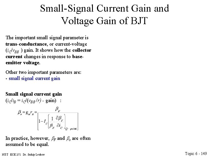
Small-Signal Current Gain and Voltage Gain of BJT The important small signal parameter is trans-conductance, or current-voltage (i. C/v. BE ) gain. It shows how the collector current changes in response to baseemitter voltage. Other two important parameters are: - small signal current gain Small signal current gain (i. C/i. B = i. C/(v. BE /r) - gain) : In practice, however, b. F and bo are often assumed to be equal. NJIT ECE 271 Dr. Serhiy Levkov Topic 6 - 149
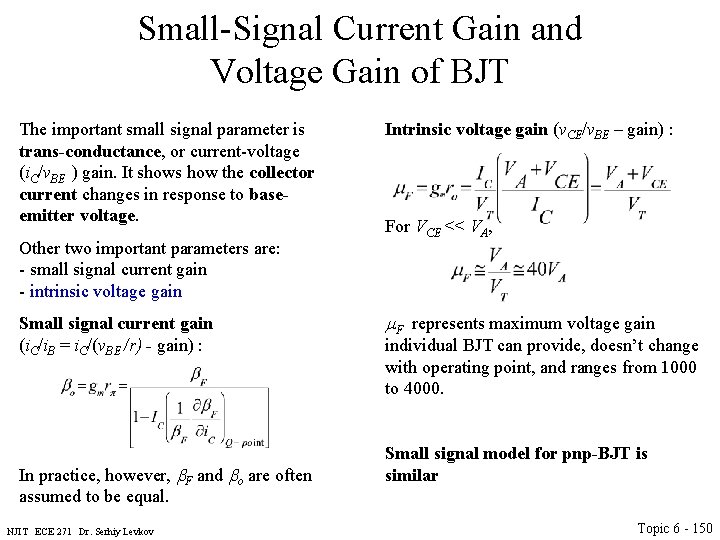
Small-Signal Current Gain and Voltage Gain of BJT The important small signal parameter is trans-conductance, or current-voltage (i. C/v. BE ) gain. It shows how the collector current changes in response to baseemitter voltage. Other two important parameters are: - small signal current gain - intrinsic voltage gain Small signal current gain (i. C/i. B = i. C/(v. BE /r) - gain) : In practice, however, b. F and bo are often assumed to be equal. NJIT ECE 271 Dr. Serhiy Levkov Intrinsic voltage gain (v. CE/v. BE – gain) : For VCE << VA, m. F represents maximum voltage gain individual BJT can provide, doesn’t change with operating point, and ranges from 1000 to 4000. Small signal model for pnp-BJT is similar Topic 6 - 150
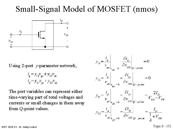
Small-Signal Model of MOSFET (nmos) Using 2 -port y-parameter network, The port variables can represent either time-varying part of total voltages and currents or small changes in them away from Q-point values. NJIT ECE 271 Dr. Serhiy Levkov Topic 6 - 151
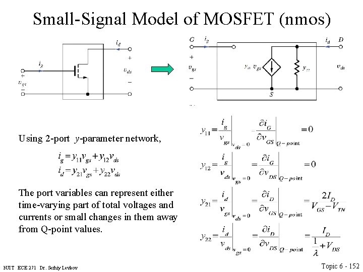
Small-Signal Model of MOSFET (nmos) Using 2 -port y-parameter network, The port variables can represent either time-varying part of total voltages and currents or small changes in them away from Q-point values. NJIT ECE 271 Dr. Serhiy Levkov Topic 6 - 152
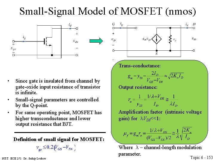
Small-Signal Model of MOSFET (nmos) Trans-conductance: • • • Since gate is insulated from channel by gate-oxide input resistance of transistor is infinite. Small-signal parameters are controlled by the Q-point. For same operating point, MOSFET has higher transconductance and lower output resistance that BJT. Output resistance: Amplification factor (intrinsic voltage gain) for l. VDS<<1: Definition of small signal for MOSFET: Where l – channel-length modulation parameter. NJIT ECE 271 Dr. Serhiy Levkov Topic 6 - 153
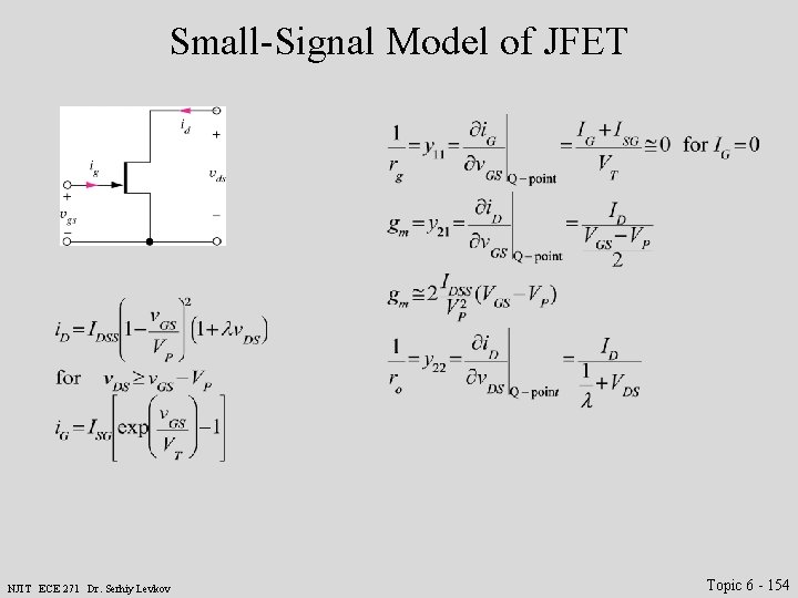
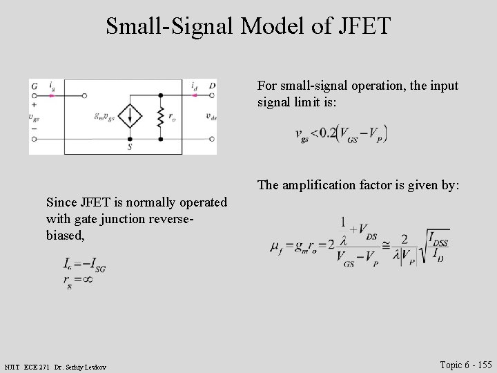
Small-Signal Model of JFET NJIT ECE 271 Dr. Serhiy Levkov Topic 6 - 154
Small-Signal Model of JFET For small-signal operation, the input signal limit is: The amplification factor is given by: Since JFET is normally operated with gate junction reversebiased, NJIT ECE 271 Dr. Serhiy Levkov Topic 6 - 155
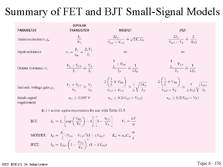
Summary of FET and BJT Small-Signal Models NJIT ECE 271 Dr. Serhiy Levkov Topic 6 - 156
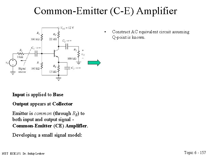
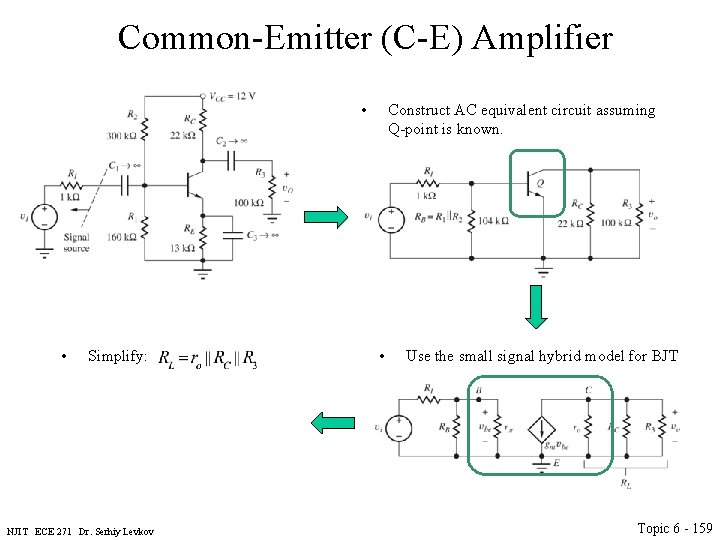
Common-Emitter (C-E) Amplifier • Construct AC equivalent circuit assuming Q-point is known. Input is applied to Base Output appears at Collector Emitter is common (through RE) to both input and output signal - Common-Emitter (CE) Amplifier. Developing a small signal model: NJIT ECE 271 Dr. Serhiy Levkov Topic 6 - 157
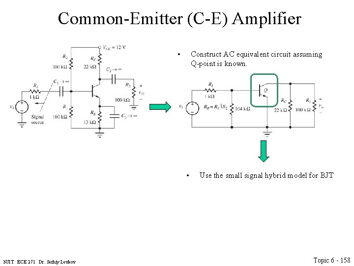
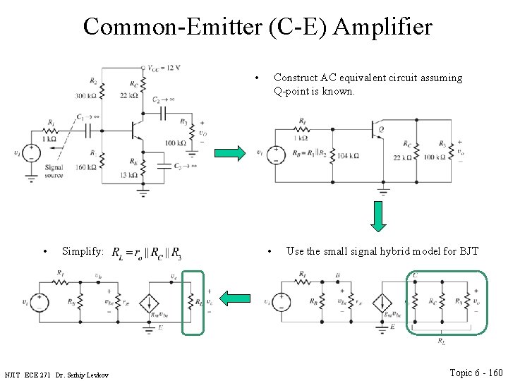
Common-Emitter (C-E) Amplifier • Construct AC equivalent circuit assuming Q-point is known. • NJIT ECE 271 Dr. Serhiy Levkov Use the small signal hybrid model for BJT Topic 6 - 158
Common-Emitter (C-E) Amplifier • • Simplify: NJIT ECE 271 Dr. Serhiy Levkov Construct AC equivalent circuit assuming Q-point is known. • Use the small signal hybrid model for BJT Topic 6 - 159
Common-Emitter (C-E) Amplifier • • Simplify: NJIT ECE 271 Dr. Serhiy Levkov Construct AC equivalent circuit assuming Q-point is known. • Use the small signal hybrid model for BJT Topic 6 - 160
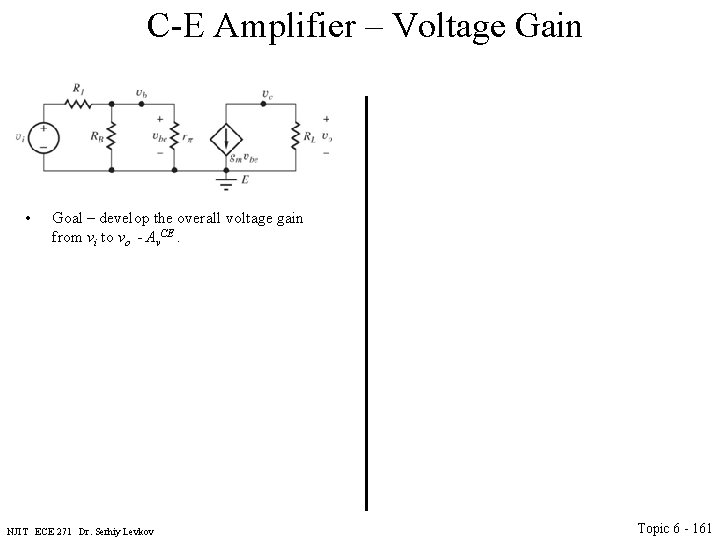
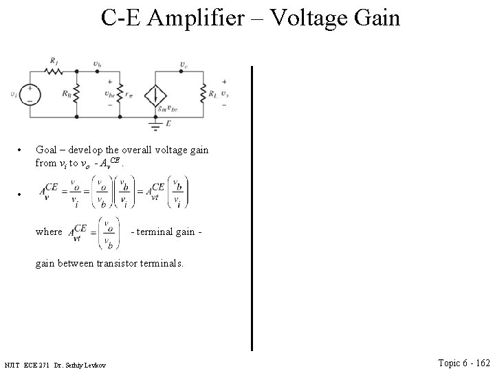
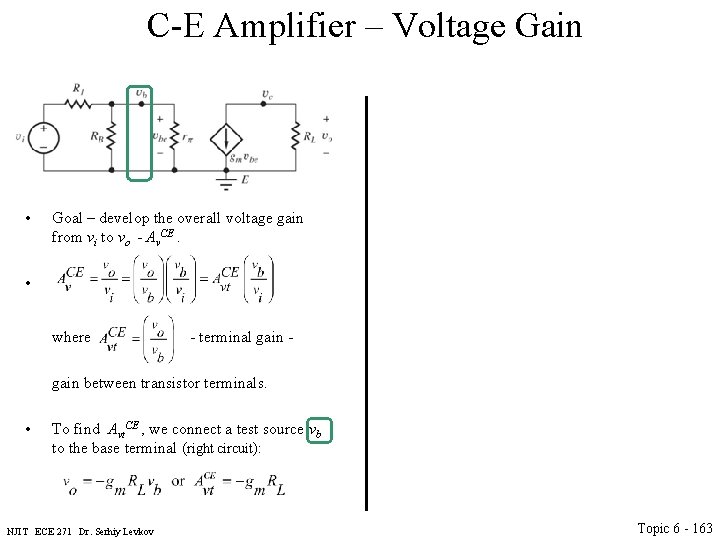
C-E Amplifier – Voltage Gain • Goal – develop the overall voltage gain from vi to vo - Av. CE. NJIT ECE 271 Dr. Serhiy Levkov Topic 6 - 161
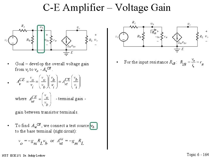
C-E Amplifier – Voltage Gain • Goal – develop the overall voltage gain from vi to vo - Av. CE. • where - terminal gain - gain between transistor terminals. NJIT ECE 271 Dr. Serhiy Levkov Topic 6 - 162
C-E Amplifier – Voltage Gain • Goal – develop the overall voltage gain from vi to vo - Av. CE. • where - terminal gain - gain between transistor terminals. • To find Avt. CE , we connect a test source vb to the base terminal (right circuit): NJIT ECE 271 Dr. Serhiy Levkov Topic 6 - 163
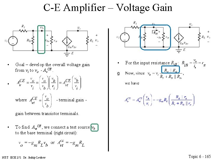
C-E Amplifier – Voltage Gain • Goal – develop the overall voltage gain from vi to vo - Av. CE. • • For the input resistance Ri. B : where - terminal gain - gain between transistor terminals. • To find Avt. CE , we connect a test source vb to the base terminal (right circuit): NJIT ECE 271 Dr. Serhiy Levkov Topic 6 - 164
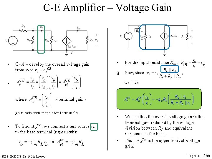
C-E Amplifier – Voltage Gain • Goal – develop the overall voltage gain from vi to vo - Av. CE. • • For the input resistance Ri. B : where - terminal gain - gain between transistor terminals. • To find Avt. CE , we connect a test source vb to the base terminal (right circuit): NJIT ECE 271 Dr. Serhiy Levkov Topic 6 - 165
C-E Amplifier – Voltage Gain • Goal – develop the overall voltage gain from vi to vo - Av. CE. • • For the input resistance Ri. B : • We see that the overall voltage gain is the terminal gain reduced by the voltage division between R 1 and equivalent resistance at the base. Thus Avt. CE is the upper limit of voltage gain. where - terminal gain - gain between transistor terminals. • To find Avt. CE , we connect a test source vb to the base terminal (right circuit): • NJIT ECE 271 Dr. Serhiy Levkov Topic 6 - 166
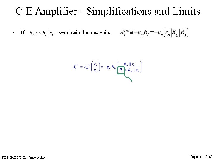
C-E Amplifier - Simplifications and Limits • If we obtain the max gain: NJIT ECE 271 Dr. Serhiy Levkov Topic 6 - 167
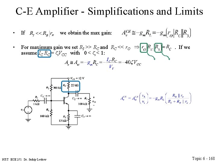
C-E Amplifier - Simplifications and Limits • If we obtain the max gain: • For maximum gain we set R 3 >> RC and RC << r. O assume IC RC = VCC with 0 < < 1: NJIT ECE 271 Dr. Serhiy Levkov . If we Topic 6 - 168
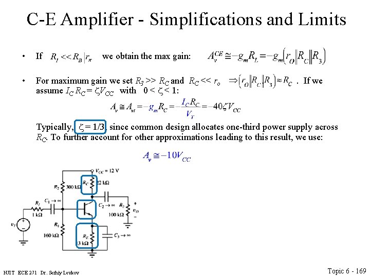
C-E Amplifier - Simplifications and Limits • If we obtain the max gain: • For maximum gain we set R 3 >> RC and RC << ro assume IC RC = VCC with 0 < < 1: . If we Typically, = 1/3, since common design allocates one-third power supply across RC. To further account for other approximations leading to this result, we use: NJIT ECE 271 Dr. Serhiy Levkov Topic 6 - 169
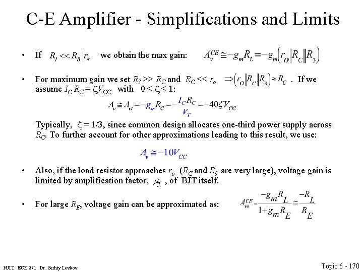
C-E Amplifier - Simplifications and Limits • If we obtain the max gain: • For maximum gain we set R 3 >> RC and RC << ro assume IC RC = VCC with 0 < < 1: . If we Typically, = 1/3, since common design allocates one-third power supply across RC. To further account for other approximations leading to this result, we use: • Also, if the load resistor approaches ro (RC and R 3 are very large), voltage gain is limited by amplification factor, mf , of BJT itself. • For large RE, voltage gain can be approximated as: NJIT ECE 271 Dr. Serhiy Levkov Topic 6 - 170
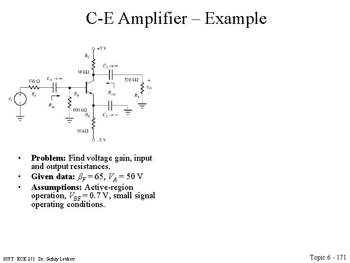
C-E Amplifier – Example • • • Problem: Find voltage gain, input and output resistances. Given data: b. F = 65, VA = 50 V Assumptions: Active-region operation, VBE = 0. 7 V, small signal operating conditions. NJIT ECE 271 Dr. Serhiy Levkov Topic 6 - 171
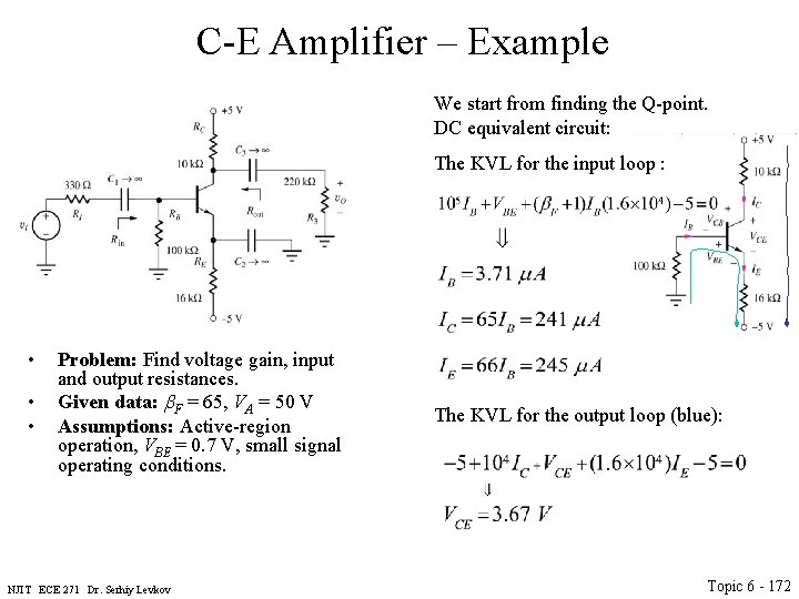
C-E Amplifier – Example We start from finding the Q-point. DC equivalent circuit: The KVL for the input loop : • • • Problem: Find voltage gain, input and output resistances. Given data: b. F = 65, VA = 50 V Assumptions: Active-region operation, VBE = 0. 7 V, small signal operating conditions. NJIT ECE 271 Dr. Serhiy Levkov The KVL for the output loop (blue): Topic 6 - 172
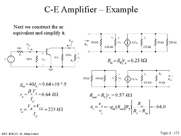
C-E Amplifier – Example Next we construct the ac equivalent and simplify it. NJIT ECE 271 Dr. Serhiy Levkov Topic 6 - 173
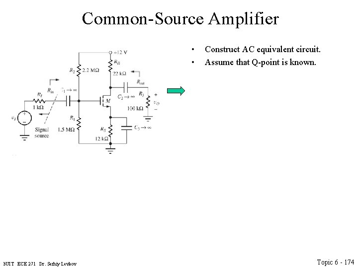
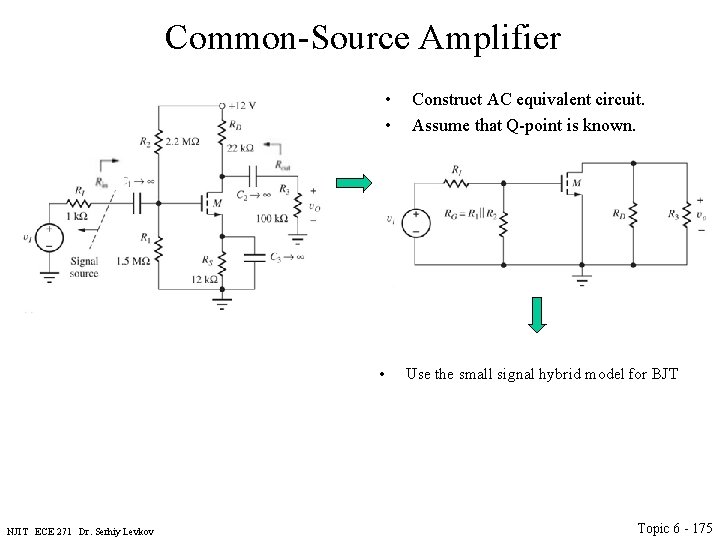
Common-Source Amplifier • • NJIT ECE 271 Dr. Serhiy Levkov Construct AC equivalent circuit. Assume that Q-point is known. Topic 6 - 174
Common-Source Amplifier • • • NJIT ECE 271 Dr. Serhiy Levkov Construct AC equivalent circuit. Assume that Q-point is known. Use the small signal hybrid model for BJT Topic 6 - 175
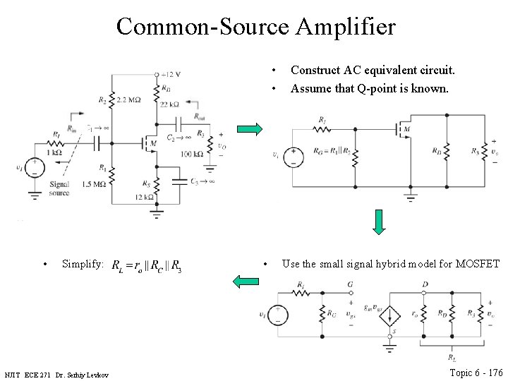
Common-Source Amplifier • • • Simplify: NJIT ECE 271 Dr. Serhiy Levkov • Construct AC equivalent circuit. Assume that Q-point is known. Use the small signal hybrid model for MOSFET Topic 6 - 176
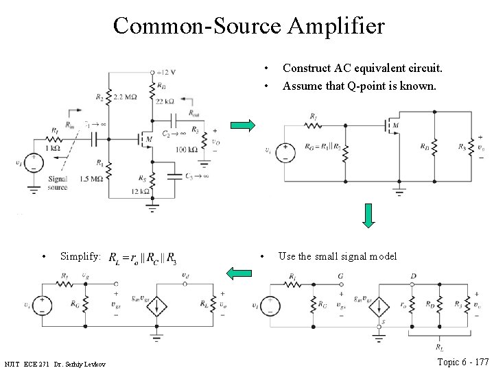
Common-Source Amplifier • • • Simplify: NJIT ECE 271 Dr. Serhiy Levkov • Construct AC equivalent circuit. Assume that Q-point is known. Use the small signal model Topic 6 - 177
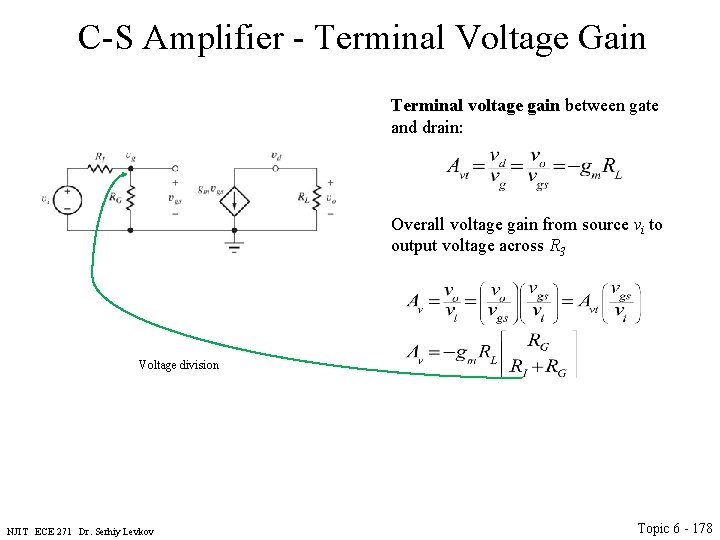
C-S Amplifier - Terminal Voltage Gain Terminal voltage gain between gate and drain: Overall voltage gain from source vi to output voltage across R 3 Voltage division NJIT ECE 271 Dr. Serhiy Levkov Topic 6 - 178
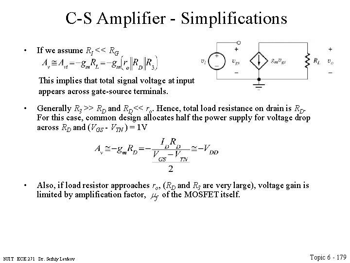
C-S Amplifier - Simplifications • If we assume RI << RG This implies that total signal voltage at input appears across gate-source terminals. • Generally R 3 >> RD and RD << ro. Hence, total load resistance on drain is RD. For this case, common design allocates half the power supply for voltage drop across RD and (VGS - VTN ) = 1 V • Also, if load resistor approaches ro, (RD and R 3 are very large), voltage gain is limited by amplification factor, mf of the MOSFET itself. NJIT ECE 271 Dr. Serhiy Levkov Topic 6 - 179
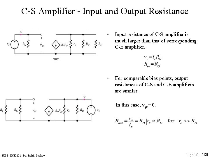
C-S Amplifier - Input and Output Resistance • Input resistance of C-S amplifier is much larger than that of corresponding C-E amplifier. • For comparable bias points, output resistances of C-S and C-E amplifiers are similar. In this case, vgs= 0. NJIT ECE 271 Dr. Serhiy Levkov Topic 6 - 180
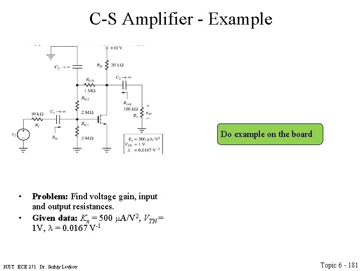
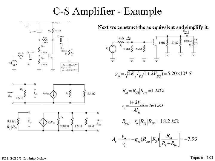
C-S Amplifier - Example Do example on the board • • Problem: Find voltage gain, input and output resistances. Given data: Kn = 500 m. A/V 2, VTN = 1 V, l = 0. 0167 V-1 NJIT ECE 271 Dr. Serhiy Levkov Topic 6 - 181
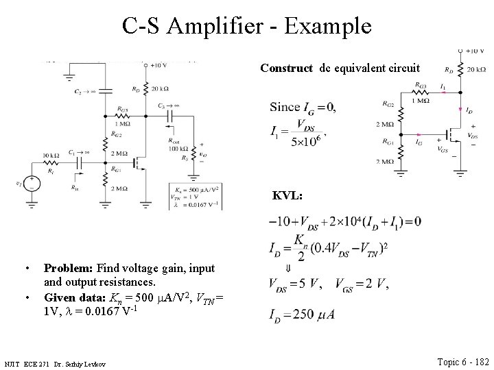
C-S Amplifier - Example Construct dc equivalent circuit KVL: • • Problem: Find voltage gain, input and output resistances. Given data: Kn = 500 m. A/V 2, VTN = 1 V, l = 0. 0167 V-1 NJIT ECE 271 Dr. Serhiy Levkov Topic 6 - 182
C-S Amplifier - Example Next we construct the ac equivalent and simplify it. NJIT ECE 271 Dr. Serhiy Levkov Topic 6 - 183
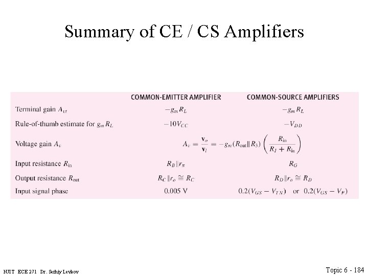
Summary of CE / CS Amplifiers NJIT ECE 271 Dr. Serhiy Levkov Topic 6 - 184