
Chapter 3 Feedback Amplifiers EET 205 Analog Electronics
Chapter 3 Feedback Amplifiers EET 205 – Analog Electronics Siti Khodijah Mazalan
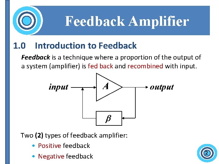
Feedback Amplifier 1. 0 Introduction to Feedback is a technique where a proportion of the output of a system (amplifier) is fed back and recombined with input. Two (2) types of feedback amplifier: • Positive feedback • Negative feedback 2

Positive Feedback Amplifier 1. 1 Positive Feedback (+) • Positive feedback is the process when the output is added to the input, amplified again, and this process continues. • Positive feedback is used in the design of oscillator and other application. 3
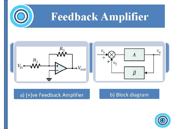
Feedback Amplifier a) [+]ve Feedback Amplifier b) Block diagram 4
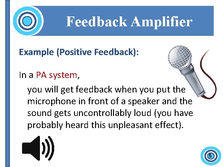
Feedback Amplifier Example (Positive Feedback): In a PA system, you will get feedback when you put the microphone in front of a speaker and the sound gets uncontrollably loud (you have probably heard this unpleasant effect). 5
Feedback Amplifier Advantage • High gain Disadvantage • Very prone to oscillation • Poor Frequency Response • More Distortion 6
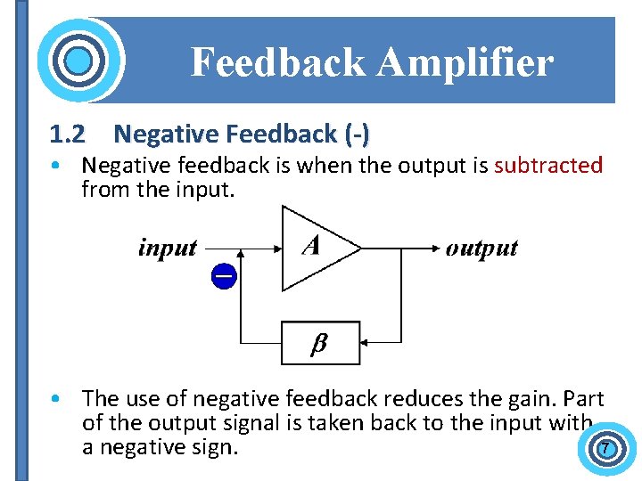
Feedback Amplifier 1. 2 Negative Feedback (-) • Negative feedback is when the output is subtracted from the input. • The use of negative feedback reduces the gain. Part of the output signal is taken back to the input with 7 a negative sign.
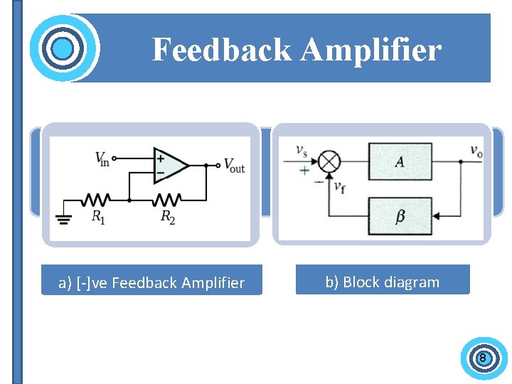
Feedback Amplifier a) [-]ve Feedback Amplifier b) Block diagram 8
Feedback Amplifier Example (Negative Feedback): Speed Control (Auto-cruise) If the car starts to speed up above the desired set-point speed, negative feedback causes the throttle to close, thereby reducing speed; similarly, if the car slows, negative feedback acts to open the throttle. 9
Feedback Amplifier Advantages of Negative Feedback 1. Stabilization of gain makes the gain less sensitive to changes in circuit components e. g. due to changes in temperature. 2. Reduction non-linear distortion make the output proportional to the input, keeping the gain constant, independent of signal level. 3. Reduction the effect of noise minimize the contribution to the output of unwanted signals generated in circuit components or extraneous interference. 4. Bandwidth Extension reduce the gain and increase the bandwidth. 5. Control of Impedance Levels input and output impedances can be increased or decreased. 10
Feedback Amplifier Disadvantages of Negative Feedback 1. Circuit Gain overall amplifier gain is reduced compared to basic amplifier. 2. Stability possibility that feedback circuit will become unstable and oscillate at high frequencies. 11
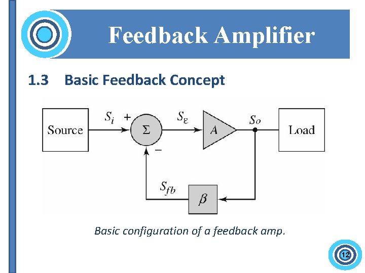
Feedback Amplifier 1. 3 Basic Feedback Concept Basic configuration of a feedback amp. 12
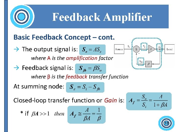
Feedback Amplifier Basic Feedback Concept – cont. The output signal is: where A is the amplification factor Feedback signal is: where β is the feedback transfer function At summing node: Closed-loop transfer function or Gain is: * if 13
Feedback Amplifier 2. 0 Classification of Amplifiers Four (4) basic categories of amplifiers based on their input/output signal relationships. ● Voltage Amplifier – [series-shunt] ● Current Amplifier – [shunt-series] ● Transconductance Amplifier – [series-series] ● Transresistance Amplifier – [shunt-shunt] 14
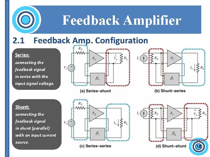
Feedback Configuration Feedback Amplifier 2. 1 Feedback Amp. Configuration Series: connecting the feedback signal in series with the input signal voltage. Shunt: connecting the feedback signal in shunt (parallel) with an input current source. 15
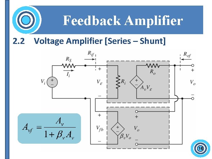
Feedback Amplifier 2. 2 Voltage Amplifier [Series – Shunt] 16
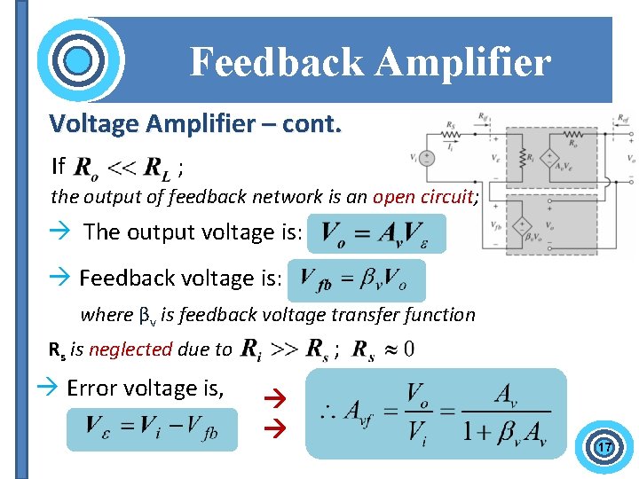
Feedback Amplifier Voltage Amplifier – cont. If ; the output of feedback network is an open circuit; The output voltage is: Feedback voltage is: where βv is feedback voltage transfer function ; Rs is neglected due to Error voltage is, 17
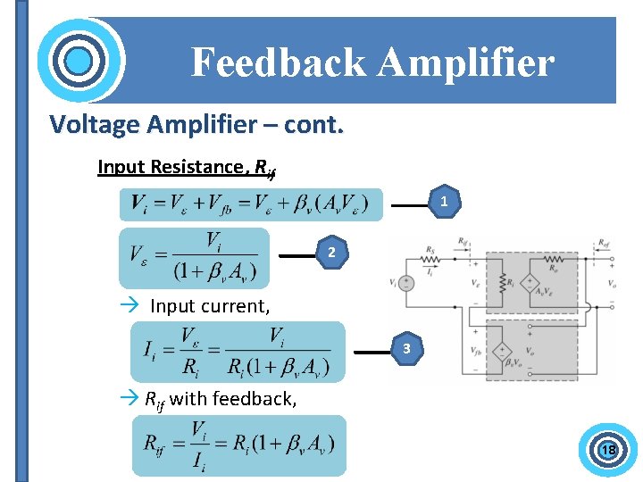
Feedback Amplifier Voltage Amplifier – cont. Input Resistance, Rif 1 2 Input current, 3 Rif with feedback, 18
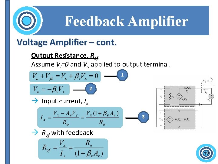
Feedback Amplifier Voltage Amplifier – cont. Output Resistance, Rof Assume Vi=0 and Vx applied to output terminal. 1 2 Input current, Ix 3 Rof with feedback 19
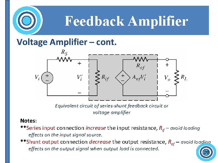
Feedback Amplifier Voltage Amplifier – cont. Equivalent circuit of series-shunt feedback circuit or voltage amplifier Notes: **Series input connection increase the input resistance, Rif – avoid loading effects on the input signal source. **Shunt output connection decrease the output resistance, Rof – avoid loading effects on the output signal when output load is connected. 20
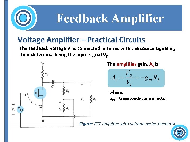
Feedback Amplifier Voltage Amplifier – Practical Circuits The feedback voltage Vf is connected in series with the source signal Vs, their difference being the input signal Vi. The amplifier gain, Av is: where, gm = transconductance factor Figure: FET amplifier with voltage-series feedback. 21
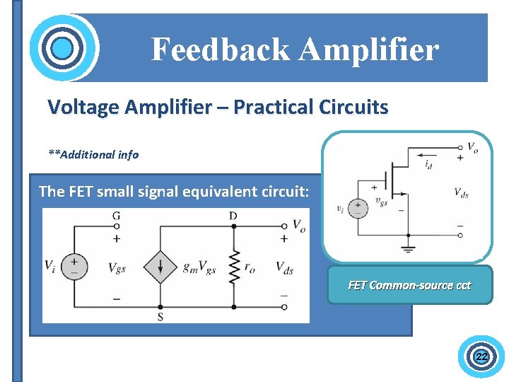
Feedback Amplifier Voltage Amplifier – Practical Circuits **Additional info The FET small signal equivalent circuit: FET Common-source cct 22
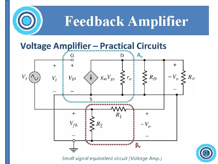
Feedback Amplifier Voltage Amplifier – Practical Circuits Av βv Small signal equivalent circuit (Voltage Amp. ) 23
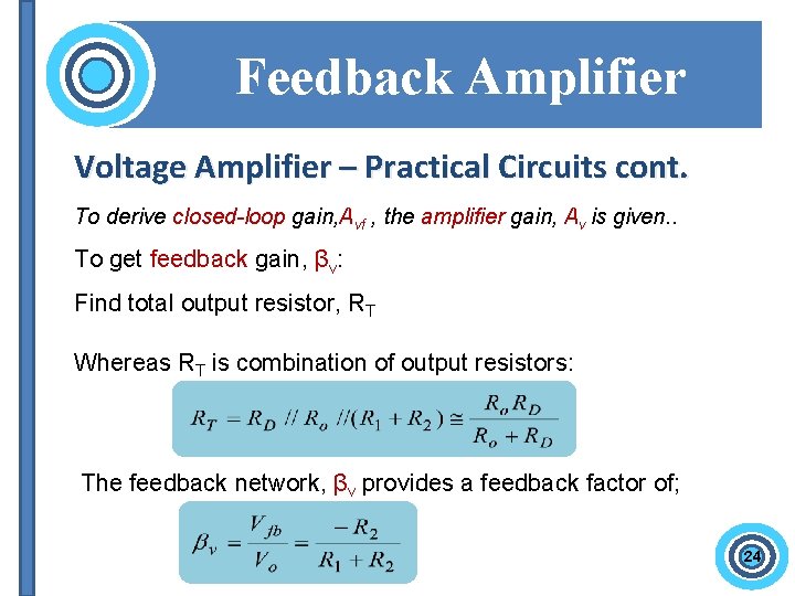
Feedback Amplifier Voltage Amplifier – Practical Circuits cont. To derive closed-loop gain, Avf , the amplifier gain, Av is given. . To get feedback gain, βv: Find total output resistor, RT Whereas RT is combination of output resistors: The feedback network, βv provides a feedback factor of; 24
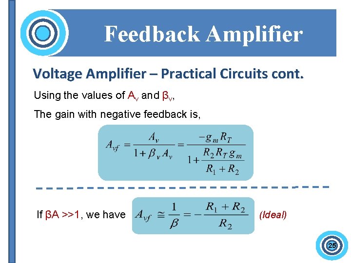
Feedback Amplifier Voltage Amplifier – Practical Circuits cont. Using the values of Av and βv, The gain with negative feedback is, If βA >>1, we have (Ideal) 25
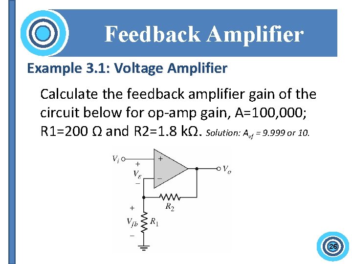
Feedback Amplifier Example 3. 1: Voltage Amplifier Calculate the feedback amplifier gain of the circuit below for op-amp gain, A=100, 000; R 1=200 Ω and R 2=1. 8 kΩ. Solution: Avf = 9. 999 or 10. 26
End of 1 st session oo. Ooo Reminder: Test 1: 7 th Nov (Wed)
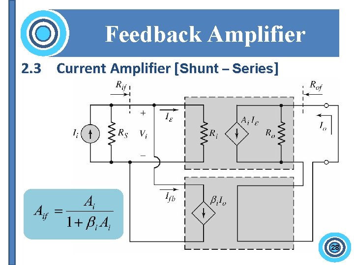
Feedback Amplifier 2. 3 Current Amplifier [Shunt – Series] 28
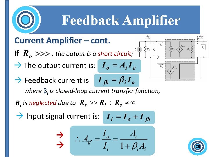
Feedback Amplifier Current Amplifier – cont. , the output is a short circuit; The output current is: Feedback current is: where βi is closed-loop current transfer function, Rs is neglected due to ; Input signal current is: 29
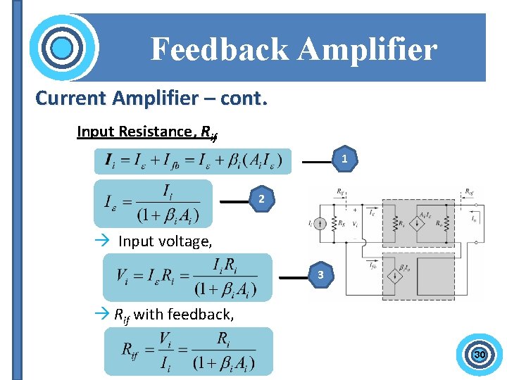
Feedback Amplifier Current Amplifier – cont. Input Resistance, Rif 1 2 Input voltage, 3 Rif with feedback, 30
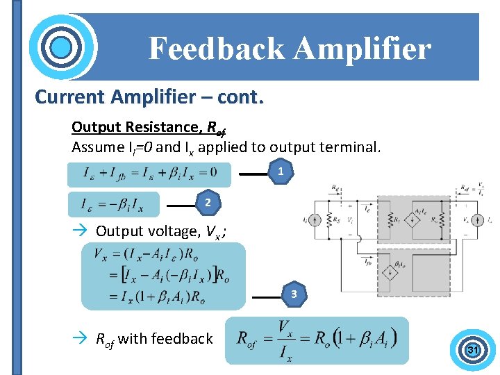
Feedback Amplifier Current Amplifier – cont. Output Resistance, Rof Assume Ii=0 and Ix applied to output terminal. 1 2 Output voltage, Vx ; 3 Rof with feedback 31
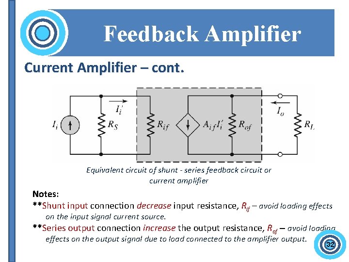
Feedback Amplifier Current Amplifier – cont. Equivalent circuit of shunt - series feedback circuit or current amplifier Notes: **Shunt input connection decrease input resistance, Rif – avoid loading effects on the input signal current source. **Series output connection increase the output resistance, Rof – avoid loading effects on the output signal due to load connected to the amplifier output. 32
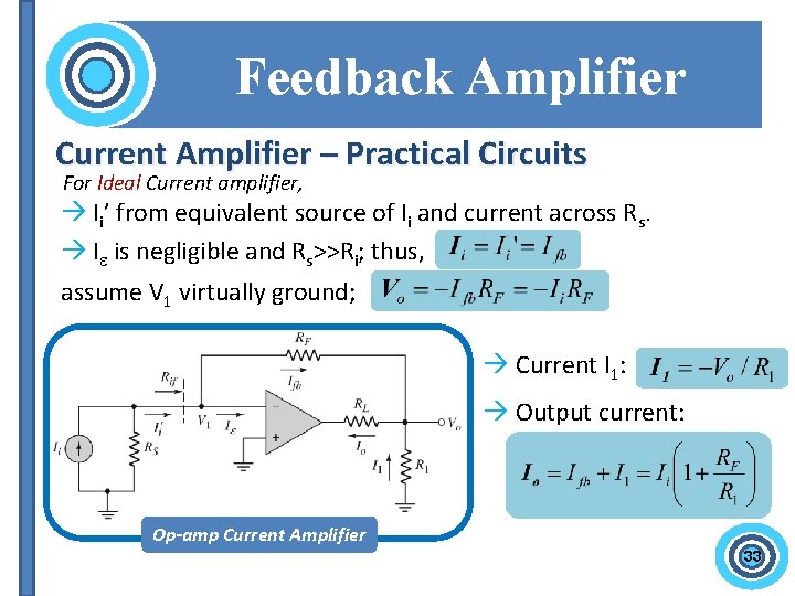
Feedback Amplifier Current Amplifier – Practical Circuits For Ideal Current amplifier, Ii’ from equivalent source of Ii and current across Rs. I is negligible and Rs>>Ri; thus, assume V 1 virtually ground; Current I 1: Output current: Op-amp Current Amplifier 33
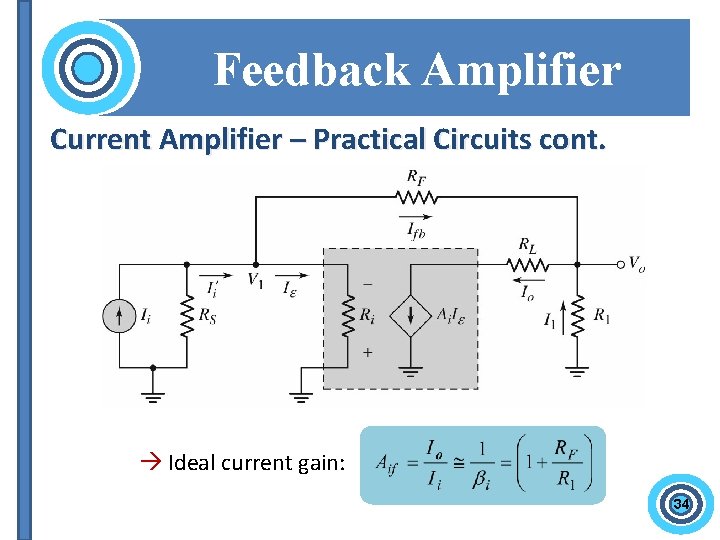
Feedback Amplifier Current Amplifier – Practical Circuits cont. Ideal current gain: 34
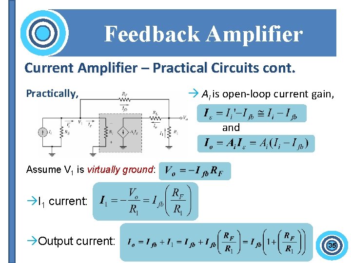
Feedback Amplifier Current Amplifier – Practical Circuits cont. Practically, Ai is open-loop current gain, and Assume V 1 is virtually ground: I 1 current: Output current: 35
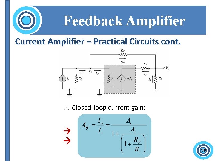
Feedback Amplifier Current Amplifier – Practical Circuits cont. Closed-loop current gain: 36

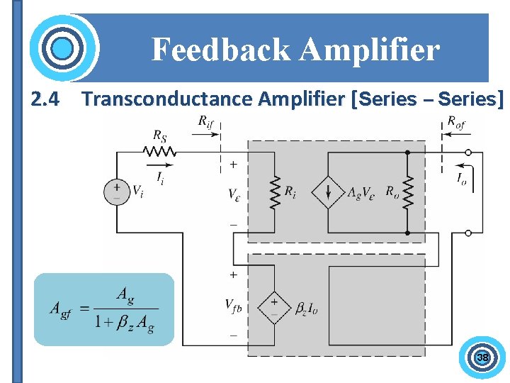
Feedback Amplifier 2. 4 Transconductance Amplifier [Series – Series] 38
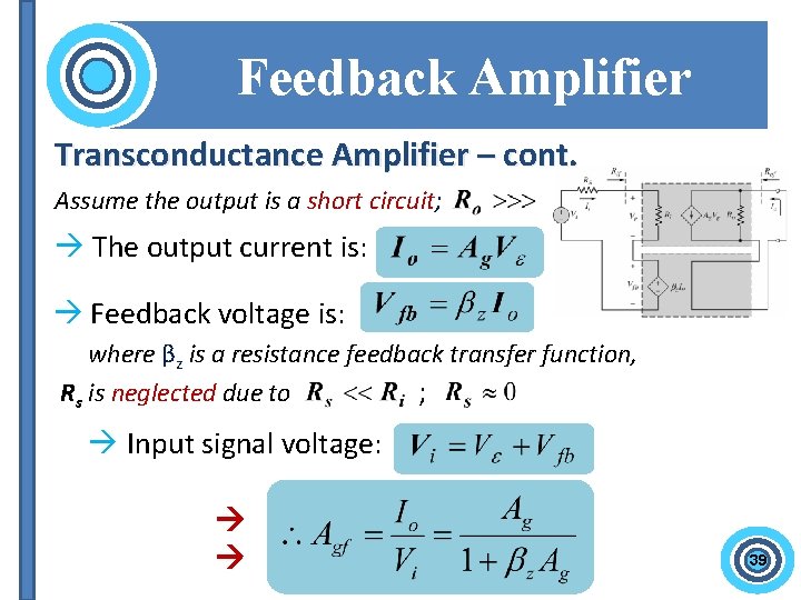
Feedback Amplifier Transconductance Amplifier – cont. Assume the output is a short circuit; The output current is: Feedback voltage is: where βz is a resistance feedback transfer function, Rs is neglected due to ; Input signal voltage: 39
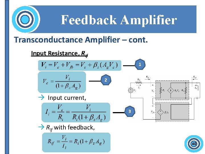
Feedback Amplifier Transconductance Amplifier – cont. Input Resistance, Rif 1 2 Input current, 3 Rif with feedback, 40
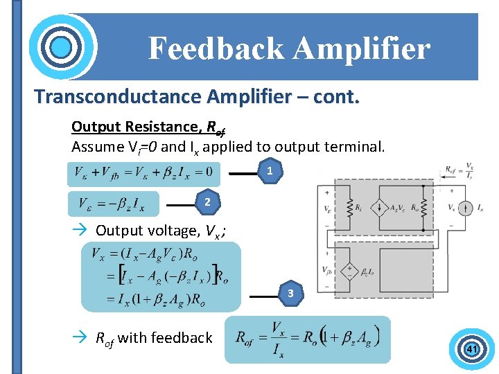
Feedback Amplifier Transconductance Amplifier – cont. Output Resistance, Rof Assume Vi=0 and Ix applied to output terminal. 1 2 Output voltage, Vx ; 3 Rof with feedback 41
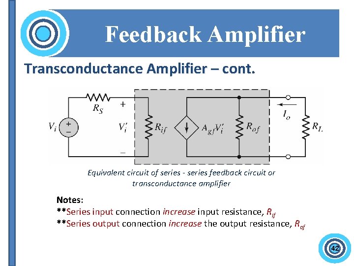
Feedback Amplifier Transconductance Amplifier – cont. Equivalent circuit of series - series feedback circuit or transconductance amplifier Notes: **Series input connection increase input resistance, Rif **Series output connection increase the output resistance, Rof 42
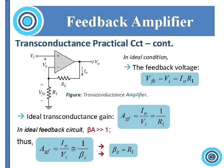
Feedback Amplifier Transconductance Practical Cct – cont. In ideal condition, The feedback voltage: Figure: Transconductance Amplifier. Ideal transconductance gain: In ideal feedback circuit, βA >> 1; thus, 43
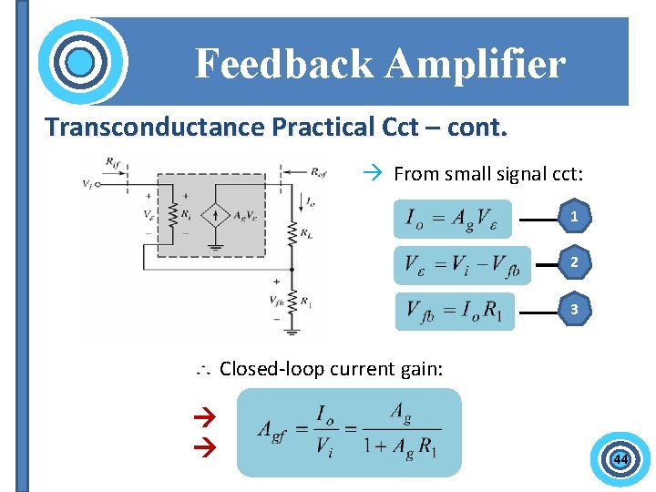
Feedback Amplifier Transconductance Practical Cct – cont. From small signal cct: 1 2 3 Closed-loop current gain: 44

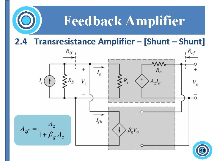
Feedback Amplifier 2. 4 Transresistance Amplifier – [Shunt – Shunt] 46
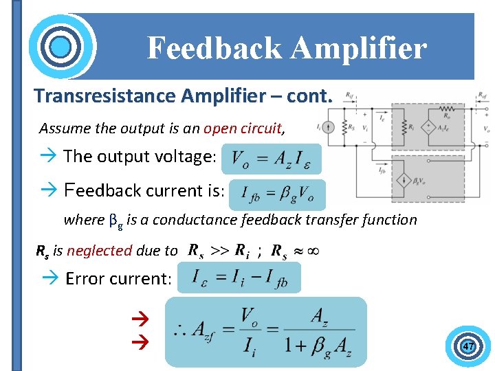
Feedback Amplifier Transresistance Amplifier – cont. Assume the output is an open circuit, The output voltage: Feedback current is: where βg is a conductance feedback transfer function Rs is neglected due to ; Error current: 47
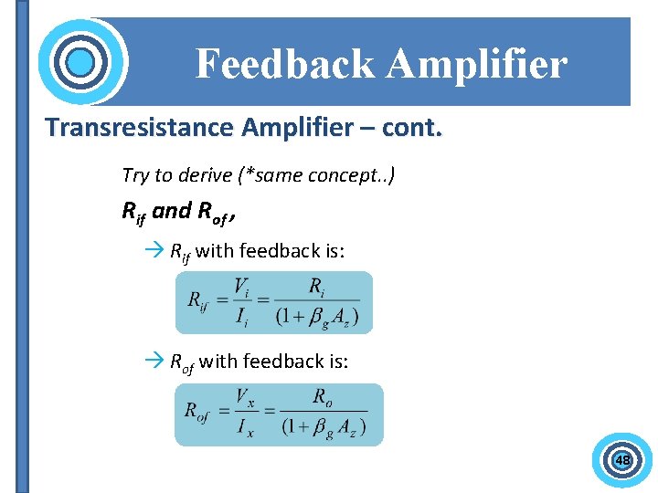
Feedback Amplifier Transresistance Amplifier – cont. Try to derive (*same concept. . ) Rif and Rof , Rif with feedback is: Rof with feedback is: 48
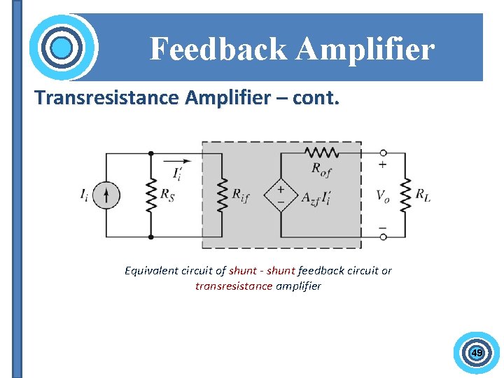
Feedback Amplifier Transresistance Amplifier – cont. Equivalent circuit of shunt - shunt feedback circuit or transresistance amplifier 49
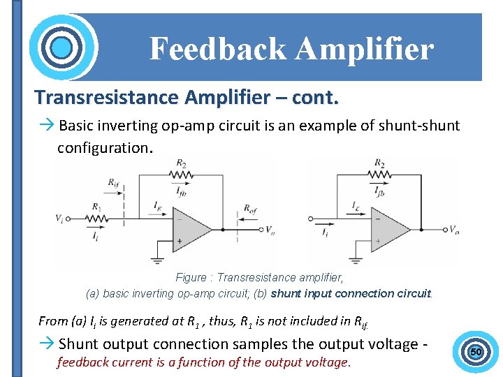
Feedback Amplifier Transresistance Amplifier – cont. Basic inverting op-amp circuit is an example of shunt-shunt configuration. Figure : Transresistance amplifier, (a) basic inverting op-amp circuit; (b) shunt input connection circuit. From (a) Ii is generated at R 1 , thus, R 1 is not included in Rif. Shunt output connection samples the output voltage feedback current is a function of the output voltage. 50
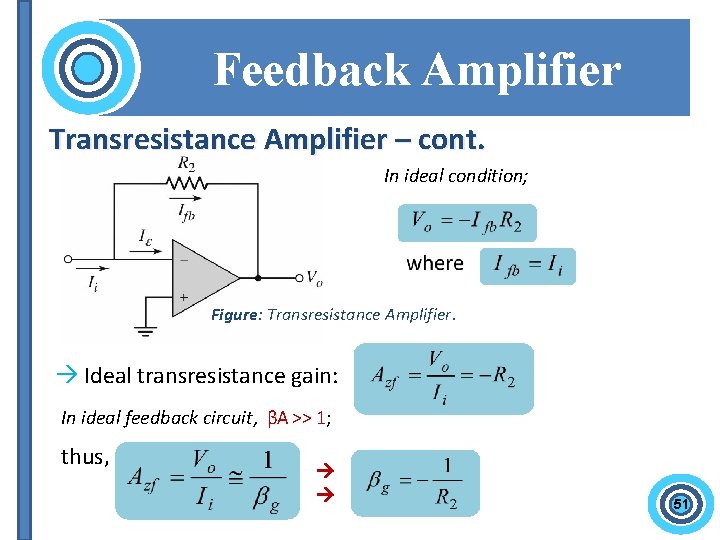
Feedback Amplifier Transresistance Amplifier – cont. In ideal condition; Figure: Transresistance Amplifier. Ideal transresistance gain: In ideal feedback circuit, βA >> 1; thus, 51
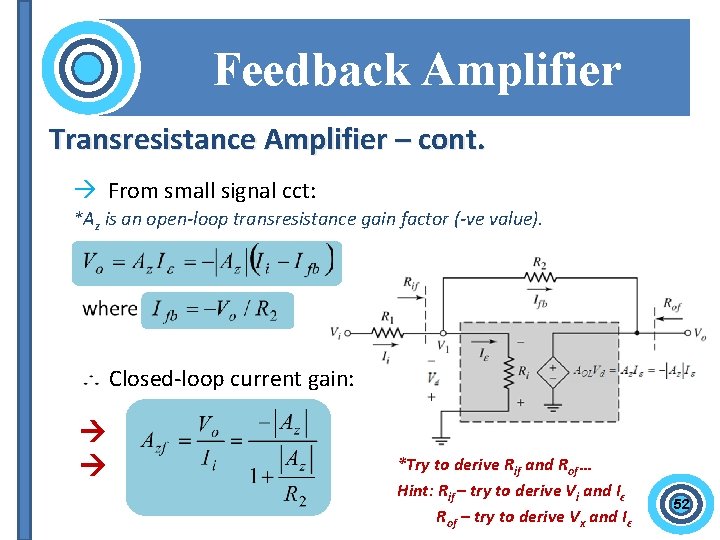
Feedback Amplifier Transresistance Amplifier – cont. From small signal cct: *Az is an open-loop transresistance gain factor (-ve value). Closed-loop current gain: *Try to derive Rif and Rof … Hint: Rif – try to derive Vi and Iε Rof – try to derive Vx and Iε 52
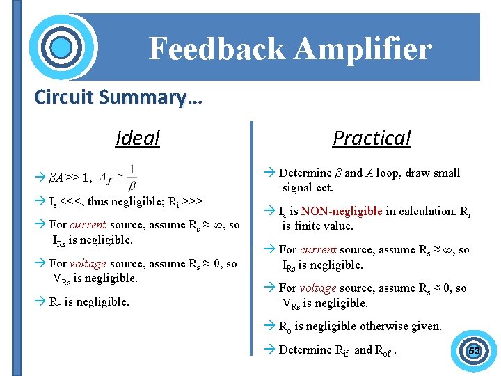
Feedback Amplifier Circuit Summary… Ideal βA >> 1, Iε <<<, thus negligible; Ri >>> For current source, assume Rs ≈ ∞, so IRs is negligible. For voltage source, assume Rs ≈ 0, so VRs is negligible. Ro is negligible. Practical Determine β and A loop, draw small signal cct. Iε is NON-negligible in calculation. Ri is finite value. For current source, assume Rs ≈ ∞, so IRs is negligible. For voltage source, assume Rs ≈ 0, so VRs is negligible. Ro is negligible otherwise given. Determine Rif and Rof. 53
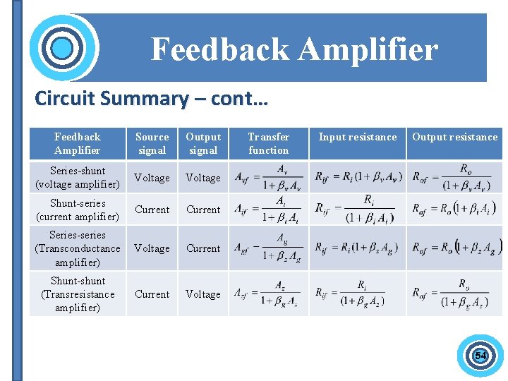
Feedback Amplifier Circuit Summary – cont… Feedback Amplifier Source signal Output signal Series-shunt (voltage amplifier) Voltage Shunt-series (current amplifier) Current Series-series (Transconductance amplifier) Voltage Current Shunt-shunt (Transresistance amplifier) Current Voltage Transfer function Input resistance Output resistance 54

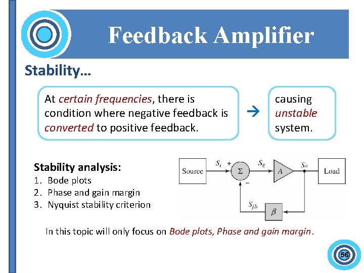
Feedback Amplifier Stability… At certain frequencies, there is condition where negative feedback is converted to positive feedback. causing unstable system. Stability analysis: 1. Bode plots 2. Phase and gain margin 3. Nyquist stability criterion In this topic will only focus on Bode plots, Phase and gain margin. 56
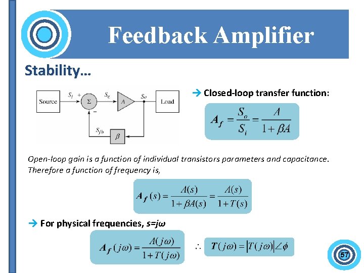
Feedback Amplifier Stability… Closed-loop transfer function: Open-loop gain is a function of individual transistors parameters and capacitance. Therefore a function of frequency is, For physical frequencies, s=jω 57
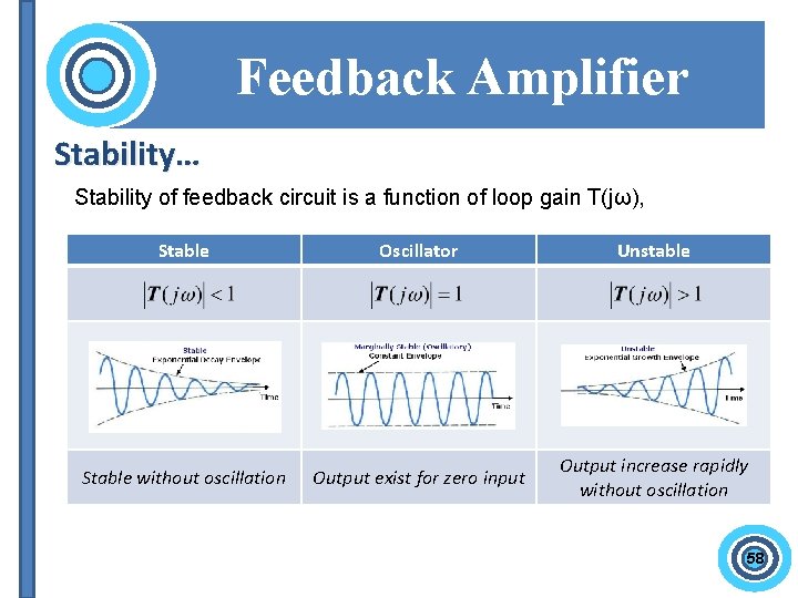
Feedback Amplifier Stability… Stability of feedback circuit is a function of loop gain T(jω), Stable Oscillator Unstable Stable without oscillation Output exist for zero input Output increase rapidly without oscillation 58
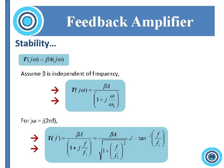
Feedback Amplifier Stability… Assume β is independent of frequency, For jω = j(2πf), 59
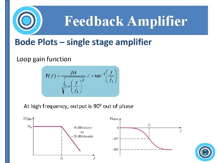
Feedback Amplifier Bode Plots – single stage amplifier Loop gain function At high frequency, output is 900 out of phase 60
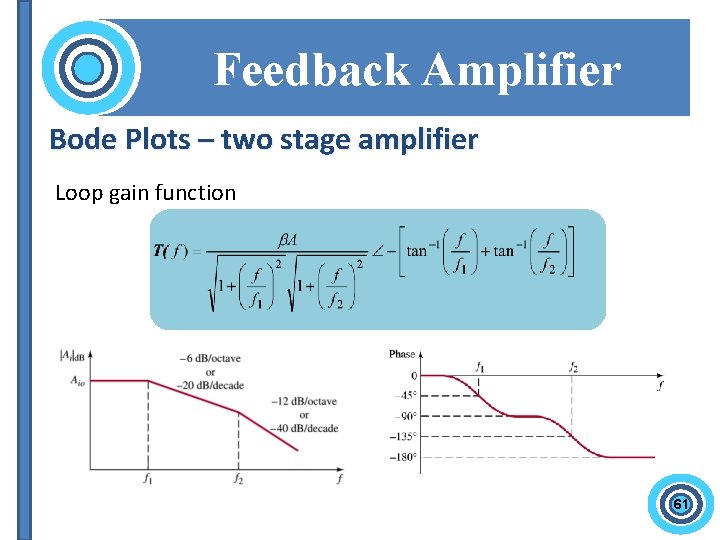
Feedback Amplifier Bode Plots – two stage amplifier Loop gain function 61
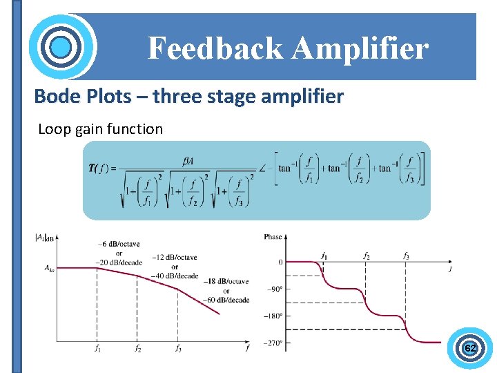
Feedback Amplifier Bode Plots – three stage amplifier Loop gain function 62
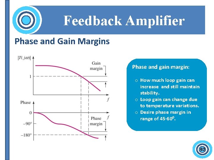
Feedback Amplifier Phase and Gain Margins Phase and gain margin: o How much loop gain can increase and still maintain stability. o Loop gain can change due to temperature variations. o Desire phase margin in range of 45 -600. 63
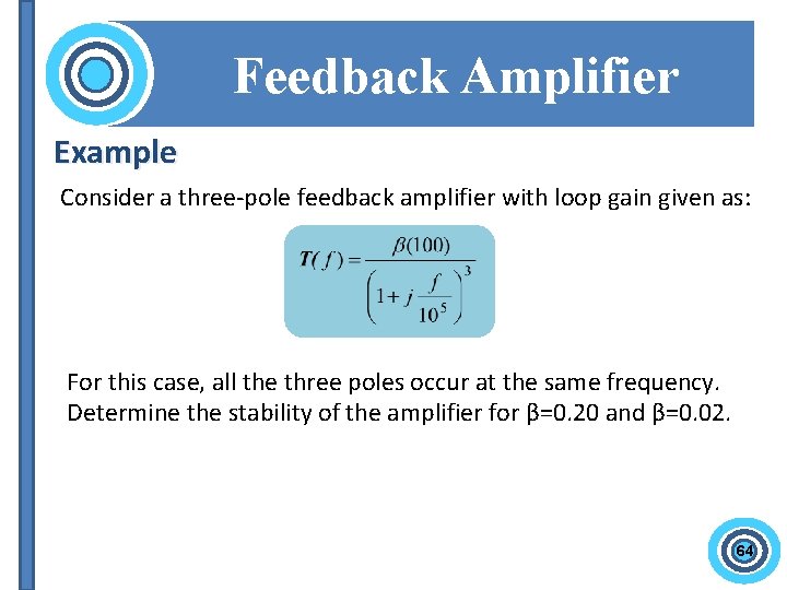
Feedback Amplifier Example Consider a three-pole feedback amplifier with loop gain given as: For this case, all the three poles occur at the same frequency. Determine the stability of the amplifier for β=0. 20 and β=0. 02. 64
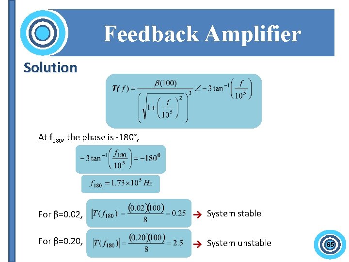
Feedback Amplifier Solution At f 180, the phase is -180°, For β=0. 02, System stable For β=0. 20, System unstable 65
End of 3 rd session oo. Ooo • Important Date: Quiz : replacement class (Date? ? ) Or 26 Nov Test 2: 4 th Dec (Tuesday), 8. 30 pm Next…

RE-TEST for TEST 1 Date: 20 November 2012 (Tuesday) Time: 12. 00 pm – 1. 30 pm Venue: Final Year Project Lab Programme EI 1). Wan Nurul Shazwani Binti Wan Abdullah 2). Mohd Zulfaqar Bin Ismail 3). Mohd Fahmi Bin A. Razak 4). Ahmad Fakhrul Syihan Bin Wisam Programme SE 1). Masliza Bte Sulaiman 2). Fahruddin Alias
- Slides: 67