Digital vs Analog Communication Advantages Increased immunity to


 bits/sec Where, B")
 Signal Processing Carrier Circuit s(t) Transmissio n Media Transmitter r(t)")


 • Angle Modulation • Frequency Modulation (FM)")
 • The amplitude of carrier signal is varied linearly with modulating")
 • Case 1: |kam(t)|≤ 1; Percentage Modulation = |kam(t)|*100% = less")
")
 Intelligence or modulating signal (b) Lower sideband (c) Carrier signal (d) Upper sideband")

 • • • Transmission Bandwidth: 2 fm Transmitted Power: Pcarrier +")


 = c(t). m(t) = Accos(2πfct). m(t) • Modulated signal")


![Balanced Modulator • s 1(t) = Ac [1 + kam(t)]cos 2πfct • s 2(t)](https://slidetodoc.com/presentation_image/3cfc8f40173f33d58414fdd7130d85ff/image-27.jpg "Balanced Modulator • s 1(t) = Ac [1 + kam(t)]cos 2πfct • s 2(t)")


 = m(t) cos 2πfct Product Modulator Low Pass Filter")
. m(t) cos(2πfct")
 • Bandwidth conservation scheme • Enables two DSB-SC modulated wave")
 Product Modulator Low Pass Filter Local Oscillator Acsin 2πfct m")
 Accos 2πfct Local Oscillator s(t)")


![4. FM broadcast band lies in a. VHF band [30 -300 MHz] b. UHF](https://slidetodoc.com/presentation_image/3cfc8f40173f33d58414fdd7130d85ff/image-40.jpg "4. FM broadcast band lies in a. VHF band [30 -300 MHz] b. UHF")


 a. fs=2 f b. fs=4 f")


- Slides: 64
Digital vs. Analog Communication • Advantages: – Increased immunity to channel noise and external interference – Flexible operation of the system – A common format for the transmission of different kinds of signals. e. g. voice, video, data – Improved security of communication through the use of encryption – Error detection and correction is possible
Digital vs. Analog Communication • Disadvantages: – Increased transmission channel bandwidth • Solution Satellite, optical fiber – Increased system complexity • Solution VLSI, ULSI • Note: – Although there is no noise & interference on channel the transmitted signal received at the receiver will not be same due to the channel imperfection & non linearity of the channel.
Resources in Communication System • Channel Bandwidth • Average transmitter power
Shannon’s Channel Capacity Theorem C = B log 2(1 + SNR) bits/sec Where, B = Channel Bandwidth C = Channel Capacity maximum rate at which the information may be transmitted without error through the channel
Basic Communication Elements m(t) Signal Processing Carrier Circuit s(t) Transmissio n Media Transmitter r(t) Signal Processing Receiver Noise Carrier Circuit
Super Heterodyne Type AM Receiver RF carrier range = 535 KHz to 1605 KHz Mid Band Frequency of IF Section = 455 KHz If Bandwidth = 10 KHz Tuning range of Local Oscillator = 80 KHz to 1150 KHz and 990 KHz to 2105 KHz Reception of double signal Image frequency Selective state required between RF Section and Mixer f. IF = f. RF – f. LO
Super Heterodyne Type FM Receiver Limiter Discriminator Loudspeaker Audio Amplifier De-emphasis network RF carrier range = 88 MHz to 108 MHz (VHF Band) Mid Band Frequency of IF Section = 10. 7 MHz If Bandwidth = 200 KHz De-emphasis is used to compensate the pre-emphasis network at transmitter side Pre-emphasis is used to improve SNR
Modulation • Modulation is the process by which some parameter of carrier signal is varied in accordance with a modulating signal (message signal) – Carrier Signal: Band pass signal – Modulating Signal: Base band signal
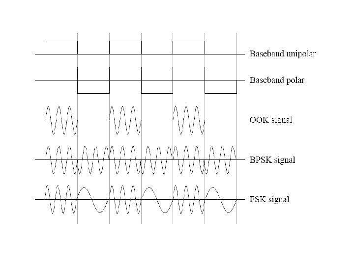
Types of Modulation • Analog Modulation (AM) • Angle Modulation • Frequency Modulation (FM) • Phase Modulation (PM) • Digital Modulation (Base band Modulation) • Amplitude Shift Keying (ASK) • Frequency Shift Keying (FSK) • Phase Shift Keying (PSK)
Amplitude Modulation (AM) • The amplitude of carrier signal is varied linearly with modulating signal. • Standard Form: s(t) = Ac [1 + kam(t)]cos 2πfct ka : Amplitude sensitivity of modulator • Envelope: a(t) = Ac [1 + kam(t)]
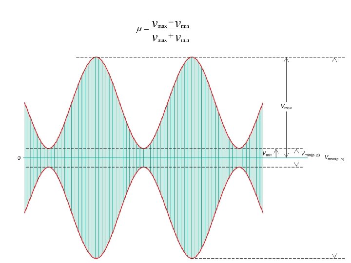
Amplitude Modulation (AM) • Case 1: |kam(t)|≤ 1; Percentage Modulation = |kam(t)|*100% = less or equal to 100% • Case 2: |kam(t)|> 1; Percentage Modulation > 100% – Receiver complexity increases – Phase reversal; envelope distortion – Over modulation
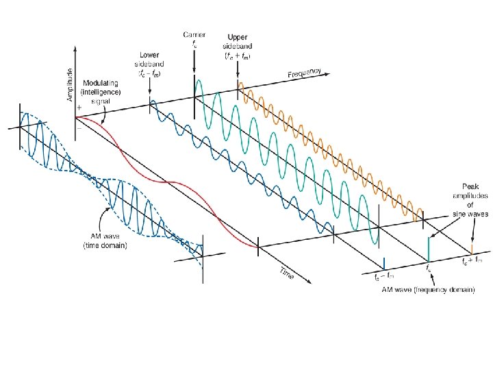
Amplitude Modulation (AM)
(a) Intelligence or modulating signal (b) Lower sideband (c) Carrier signal (d) Upper sideband (e) Composite AM wave
Frequency Domain AM Signal
Amplitude Modulation (AM) • • • Transmission Bandwidth: 2 fm Transmitted Power: Pcarrier + PUSB + PLSB Pcarrier: ½ Ac 2 PUSB: μ 2 Ac 2 PLSB: μ 2 Ac 2 Modulation Factor, μ = ka. Am
Generation of AM • Square Law Modulator • Switching Modulator
Square Law Modulator Unwanted signal are removed by tuned band pass filter of Mid Band Frequency = fc Bandwidth = 2 fm fc > 3 fm
Switching Modulator Unwanted signal are removed by tuned band pass filter of Mid Band Frequency = fc Bandwidth = 2 fm fc > 2 fm
Detection/Demodulation of AM • Square Law detector • Envelope Detector
Square Law Detector After LPF, wanted component can be detected
Envelope Detector Rs. C << 1/fc ; charging time should be less compared to carrier time. 1/fc << RLC << 1/w ; discharging time constant is larger than charging time constant
DSB-SC • Time domain s(t) = c(t). m(t) = Accos(2πfct). m(t) • Modulated signal undergoes a phase reversal whenever the message signal crosses zero. (due to absence of carrier signal on modulated wave) ½ Ac. M(0)
DSB-SC Generation • Balanced Modulator • Ring Modulator/Lattice or Double Balanced Modulator
Balanced Modulator
Balanced Modulator • s 1(t) = Ac [1 + kam(t)]cos 2πfct • s 2(t) = Ac [1 - kam(t)]cos 2πfct • s(t) = s 1(t) - s 2(t) = 2 ka. Acm(t)cos 2πfct
Ring Modulator Required term can be filtered out by using BPF of Mid Band Frequency = fc Bandwidth = 2 fm fc > f m
Detection of DSB-SC • Coherent Detection/Synchronous detection • Costas Loop
Coherent Detection of DSB-SC s(t) = m(t) cos 2πfct Product Modulator Low Pass Filter Vo(t)= ½ cos(ɸ). m(t) s(t) = m(t) cos(2πfct + ɸ) Local Oscillator • After LPF, Vo(t)= ½ cos(ɸ). m(t) • When ɸ = 900; Vo(t)= 0 Quadrature Null effect
Costas Loop I - Channel Product Modulator Low Pass Filter ½ cos(ɸ). m(t) cos(2πfct + ɸ) s(t) = Acm(t) cos 2πfct VCO Phase Discriminator -900 Phase Shifter sin(2πfct + ɸ) Product Modulator Q - Channel Low Pass Filter ½ sin(ɸ). m(t)
Quadrature Carrier Multiplexing (QAM) • Bandwidth conservation scheme • Enables two DSB-SC modulated wave to occupy the same transmission bandwidth • To maintain the synchronization QAM sends a pilot signal out side the pass band.
QAM Transmitter m 1(t) Product Modulator Low Pass Filter Local Oscillator Acsin 2πfct m 2(t) Product Modulator ∑ + Accos 2πfct -900 Phase Shifter + Multiplexed signal
QAM Receiver Product Modulator Low Pass Filter m 1(t) Accos 2πfct Local Oscillator s(t) -900 Phase Shifter Acsin 2πfct Product Modulator Low Pass Filter m 2(t)
NT Old Questions and Answer
1. In a certain modulation system, the demodulation index is halved when the modulating frequency is doubled keeping the modulating voltage the same. The modulation system is a. AM b. FM c. PM d. PWM Ans: b
2. The line coding technique used in E 1 digital stream is a. AMI [DS 1, E 1] b. NRZ c. HDB 3 [E 1] d. CMI Ans: c B 8 ZS [DS 1/T 1] Polar Biphase: Manchester and Diff. Manchester [802. 3 Ethernet LAN, 802. 5 Token Ring LAN]
3. If sampling time is less than the Nyquist Interval, then: a. Bandwidth increases b. Channel Capacity Increases c. Guard Time Reduces d. Simpler filters may be used to obtain the original signal Ans: c (check)
4. FM broadcast band lies in a. VHF band [30 -300 MHz] b. UHF band [300 -3000 MHz] c. SHF band [3 -30 GHz] d. HF Band [3 -30 MHz] Ans: a
5. The number of voice frequency channels in E 1 PCM line is a. 16 b. 24 [T 1] c. 30 [E 1] d. 64 Ans: c
6. The transmission rate of STM 1 in optical fiber is: a. 155. 52 Mb/s b. 2. 048 Mb/s [E 1] c. 140 Mb/s [PDH; E 1 Hierarchy, E 4 = 139. 264 Mb/s] d. 1. 54 Mb/s [T 1] Ans: a STM-4: 622 Mb/s STM-16: 2. 4 Gb/s E 3: 34 Mb/s
7. Total voice chnnels avaiable in one PCM link of E 1 standard: a. 24 channels [T 1] b. 22 channels c. 30 channels [E 1] d. 32 channels [E 1; total channles] Ans: c
8. Line Coding technique used in 34 Mb/s digital stream is: a. PSK b. AMI c. CMI d. HDB 3 [E 1; E 3 = 34 Mb/s] Ans: d
9. Which of the following modulation techniques has low out-of band spurious radiation? a. QAM b. PSK c. FSK d. MSK Ans: d
GMSK has a main lobe 1. 5 times that of QPSK GMSK<QPSK Theoretical Bandwidth efficiency limits MSK 1 bit/second/Hz BPSK 1 bit/second/Hz QPSK 2 bits/second/Hz 8 PSK 3 bits/second/Hz 16 QAM 4 bits/second/Hz 32 QAM 5 bits/second/Hz 64 QAM 6 bits/second/Hz 256 QAM 8 bits/second/Hz OFDM >10 (depends on the type of modulation and the no. of subcarriers) GMSK 1. 35 FSK <1 (depends on modulation index)
10. Which modulation technique occupies least spectral bandwidth? a. QPSK b. BPSK c. 16 QAM d. 64 QAM Ans: d
11. A band limited signal of fm Hz can be represented without losing any information by its samples uniformly separated at or less than a. 2 fm sec b. 1/2 fm sec [fs=2 fm] c. 2/fm sec d. fm/2 sec Ans: b
12. Which of the following digital modulation system is more resistant to the noise? a. ASK b. FSK c. PSK d. All of above Ans: c PSK>FSK>ASK
13. Which one of the following helps to reduce the qunatizing noise in Pulse Code Modulatioin? a. Higher Sampling Rate b. Lower Sampling Rate c. Higher number of quantizing levels d. Lower number of qunatizing levels Ans: c
14. STM-1 module of an synchronous digital hierarchy has a transmission rate of a. 34 kb/s b. 65 Mb/s c. 144 kb/s [B-ISDN] d. 155 Mb/s Ans: d
15. Digital paths betwen countries, which have adapted different encoding laws, carry signals encoded in accordance with a. A law b. u law (meu law) c. Both A and u law d. None of above Ans: c
16. Essential use of PLL technique is marked with feature: a. Frequency stability b. Amplification c. Carrier generation d. All of these Ans: a
17. Quantizing is the process of converting a continuous signal to one that is discrete in a. Amplitude b. Wavelength c. Phase d. None Ans: a
18. Sampling theorem states that (where fs=sampling frequency) a. fs=2 f b. fs=4 f c. fs=6 f d. None Ans: a
19. A modulation is a system to a. separete two frequencies b. impress the information on to a radio frequency carrier c. extract informationfrom the carrier d. amplify the audio frequency signal Ans: b
20. The number of E 1 in STM-1 audio equipment is a. 33 b. 43 c. 63 d. 73 Ans: c
21. If the bandwidth of double side band suppressed carrier AM signal is 30 KHz, the maximum frequency of the modulating signal is limited to a. 10 KHz b. 15 KHz c. 30 KHz d. 60 KHz Ans: b BW of DSB-SC = 2 w
22. Modulation is the process of a. reducing distortion in RF amplifiers b. improving thermal stability c. generating constant-frequency radio waves d. combining audio and radio-frequency waves at the transmitting end of a communication system Ans: d
23. In 2. 048 Mbps transmission frame one time slot is a. 34 Kbps b. 64 Kbps c. 74 Kbps d. None of above Ans: b
24. Phase modulation is commonly used for data transmission mainly because a. phase can be varied from +180 to -180 degree b. demodulation is very easy c. it is resistant to the effects of noise d. it gies highest date rates that can be transmitted over a given channel Ans: c
25. De-modulation is a process whereby a. a signal is received from the system b. a carrier is received from the sytem c. an intelligence is recovered from the carrier d. an intelligence is impressed on the carrier Ans: c
26. The VHF band is a. 0. 3 - 3 MHz b. 3 - 30 MHz c. 30 - 300 MHz d. 0. 3 - 3 GHz Ans: c
What is the difference between PCM and ADPCM? 1. In ADPCM, difference between two consecutive samples is used to represent the signal, whereas sample values are directly used in PCM. 2. In PCM, the size of the interval between two samples is fixed, whereas it can be varied in ADPCM. 3. ADPCM needs a less amount of bits to represent a signal compared to PCM. 4. Decoding a PCM signal is easier than an ADPCM signal.