Digital Transmission Analog to Digital Conversion 2 nd


 PCM consists of three steps to digitize an analog")


 Consider the analog Signal x(t). 2 t X(n. Ts) 10 Ts The")


 of")


 PCM is a very complex technique. Other techniques have been")


- Slides: 34
Digital Transmission Analog to Digital Conversion 2 nd semester 1438 -1439 NET 205: Data Transmission and Digital Communication
2 205 NET CLO 1 -Introduction to Communication Systems and Networks architecture OSI Reference Model. 2 - Data Transmission Principles 3 - Transmission medias 4 - Data modulation and encoding
3 Outline Pulse Code Modulation Sampling Quantizing Encoding PCM SNR and Bandwidth Delta Modulation
4 ANALOG-TO-DIGITAL CONVERSION A digital signal is superior to an analog signal because it more robust to noise can easily be recovered, corrected and amplified. Pulse code modulation and delta modulation are two techniques that change an analog signal to digital data. After the digital data are created (digitization), we can use one of the techniques described before to convert the digital data to a digital signal.
5 Pulse Code Modulation (PCM) PCM consists of three steps to digitize an analog signal: 1. Sampling : The analog signal is sampled 2. Quantization: The sampled signal is quantized 3. Binary encoding: The quantized values are encoded as streams of bits.
6 Sampling Analog signal is sampled every TS secs. Ts is referred to as the sampling interval or period. fs = 1/Ts is called the sampling rate or sampling frequency. This process is sometimes referred to as pulse amplitude modulation PAM and the outcome is a signal with analog (non integer) values
7 Sampling Methods There are 3 sampling methods: Ideal - an impulse at each sampling instant Natural - a pulse of short width with varying amplitude Flattop - sample and hold, like natural but with single amplitude value
8 Nyquist Theorem According to the Nyquist theorem, the sampling rate must be at least 2 times the highest frequency contained in the signal.
9 Example A complex low-pass signal has a bandwidth of 200 k. Hz. What is the minimum sampling rate for this signal? Solution The bandwidth of a low-pass signal is between 0 and f, where f is the maximum frequency in the signal. Therefore, we can sample this signal at 2 times the highest frequency (200 k. Hz). The sampling rate is therefore 400, 000 samples per second.
10 Example A complex bandpass signal has a bandwidth of 200 k. Hz. What is the minimum sampling rate for this signal? Solution We cannot find the minimum sampling rate in this case because we do not know where the bandwidth starts or ends. We do not know the maximum frequency in the signal.
11 Filtering Before we sample, we have to filter the signal to limit the maximum frequency of the signal as it affects the sampling rate. Filtering should ensure that we do not distort the signal, i. e. remove high frequency components that affect the signal shape.
12 Quantization Sampling results in a series of pulses of varying amplitude values ranging between two limits: a min and a max. The amplitude values are infinite between the two limits. We need to map the infinite amplitude values onto a finite set of known values. This is achieved by doing Quantization process.
13 Quantization steps 1. The original analog signal has instantaneous amplitudes between Vmin and Vmax 2. We divide the range into L zones, each of height Δ (zone width) Δ = (Vmax - Vmin )/L 3. We assign quantized values of 0 to L – 1 (resulting in L values) to the midpoint of each zone. 4. We approximate the value of the sample amplitude to the quantized values
14 Example : Quantization Zones Assume we have a voltage signal with amplitutes Vmin=-20 V and Vmax=+20 V. We decide to have eight levels L=8. Zone width = (20 - -20)/8 = 5 The 8 zones are: -20 to -15, -15 to -10, -10 to -5, -5 to 0, 0 to +5, +5 to +10, +10 to +15, +15 to +20 The midpoints are: -17. 5, -12. 5, -7. 5, -2. 5, 7. 5, 12. 5, 17. 5
15 Example: Assigning Codes to Zones Each zone is then assigned a binary code. The number of bits required to encode the zones, or the number of bits per sample as it is commonly referred to, is obtained as follows: nb = log 2 L Given our example, nb = 3 The 8 zone (or level) codes are therefore: 000, 001, 010, 011, 100, 101, 110, and 111 Assigning codes to zones: 000 will refer to zone -20 to -15 001 to zone -15 to -10, etc.
16
Quantization Error When a signal is quantized, we introduce an error - the coded signal is an approximation of the actual amplitude value. The difference between actual and midpoint value is referred to as the quantization error. The more zones, the smaller which results in smaller errors.
18 Encoding After each sample is quantized and the number of bits per sample is decided, each sample can be changed to an nb-bit code word. The bit rate can be found from the formula Bit rate = sampling rate × number of bits per sample=fs × nb
19
20 Example We want to digitize the human voice. What is the bit rate, assuming 8 bits per sample? Solution The human voice normally contains frequencies from 0 to 4000 Hz. So the sampling rate and bit rate are calculated as follows: Sampling rate = 4000 × 2 = 8000 samples/s Bit rate = 8000 × 8 = 64, 000 bps = 64 kbps
10 x(t) Consider the analog Signal x(t). 2 t X(n. Ts) 10 Ts The signal is first sampled 2 n
10 2 8 6 4 dividing the range into 4 zones 2 n 3 2 1 0 assign quantized values of 0 to 3 to the midpoint of each zone. n
3 2 1 0 approximating the value of the sample amplitude to the quantized values. 11 3 10 2 01 1 00 n 0 Each zone is assigned a binary code n
11 3 10 2 01 1 00 0 01 11 11 11 01 The sequence bits if the samples 01111111010000 00 00 Use one of the line code scheme to get the digital signal n
25 Quantization Error and SNR The quantization error changes the signal-to-noise ratio (SNR) of the signal, which in turn reduces the upper limit capacity according to Shannon. SNRd. B = 6. 02 nb + 1. 76 d. B
26 Example What is the SNRd. B value if we quantize a signal using 8 levels? We can use the formula to find the quantization. We have eight levels 3 bits per sample, so SNRd. B = 6. 02(3) + 1. 76 = 19. 82 d. B Increasing the number of levels increases the SNR
27 PCM Bandwidth If we digitize a low-pass analog signal with bandwidth Banalog , the new minimum bandwidth of the channel that can pass this digitized signal Bmin = nb x Banalog Example We have a low-pass analog signal of 4 k. Hz. If we send the analog signal, we need a channel with a minimum bandwidth of 4 k. Hz. If we digitize the signal and send 8 bits per sample, we need a channel with a minimum bandwidth of 8 × 4 k. Hz = 32 k. Hz.
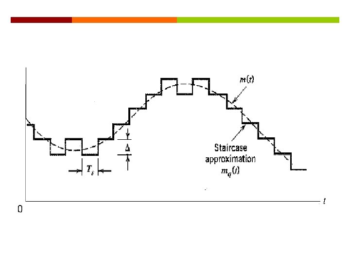
28 Delta Modulation (DM) PCM is a very complex technique. Other techniques have been developed to reduce the complexity of PCM. The simplest is delta modulation. PCM finds the value of the signal amplitude for each sample; DM finds the change from the previous sample.
29 Delta Modulation In Delta Modulation, only one bit is transmitted per sample. That bit is: 1 if the current sample > the previous sample 0 if the current sample < the previous sample Since so little information is transmitted, delta modulation requires higher sampling rates than PCM for equality of reproduction
Modulater 1 - A staircase approximation of the message signal is derived The analog signal is approximated with a staircase approximation signal (series of segments ). Each segment of the approximated signal is compared to the message signal: If the approximation fall below the signal at any sampling epoch the segment is increased by ∆. If the approximation lies above the signal at any sampling epoch the segment is diminished by ∆. So, the time and amplitude axes are quantized.
Modulator 2 - encoding This scheme sends only one bit each segment. if the segment at time tn+1 is higher in amplitude value than the segment at time tn, then a bit “ 1” is used to indicate the positive value. If the segment is lower in value resulting in a negative value, a “ 0” is used.
This scheme works well for small changes in signal values between samples. If changes in amplitude are large, this will result in large errors.
34 Any Questions ?